About steps per mm.
I have ball screws and I don’t think they are imperial, I should check them.
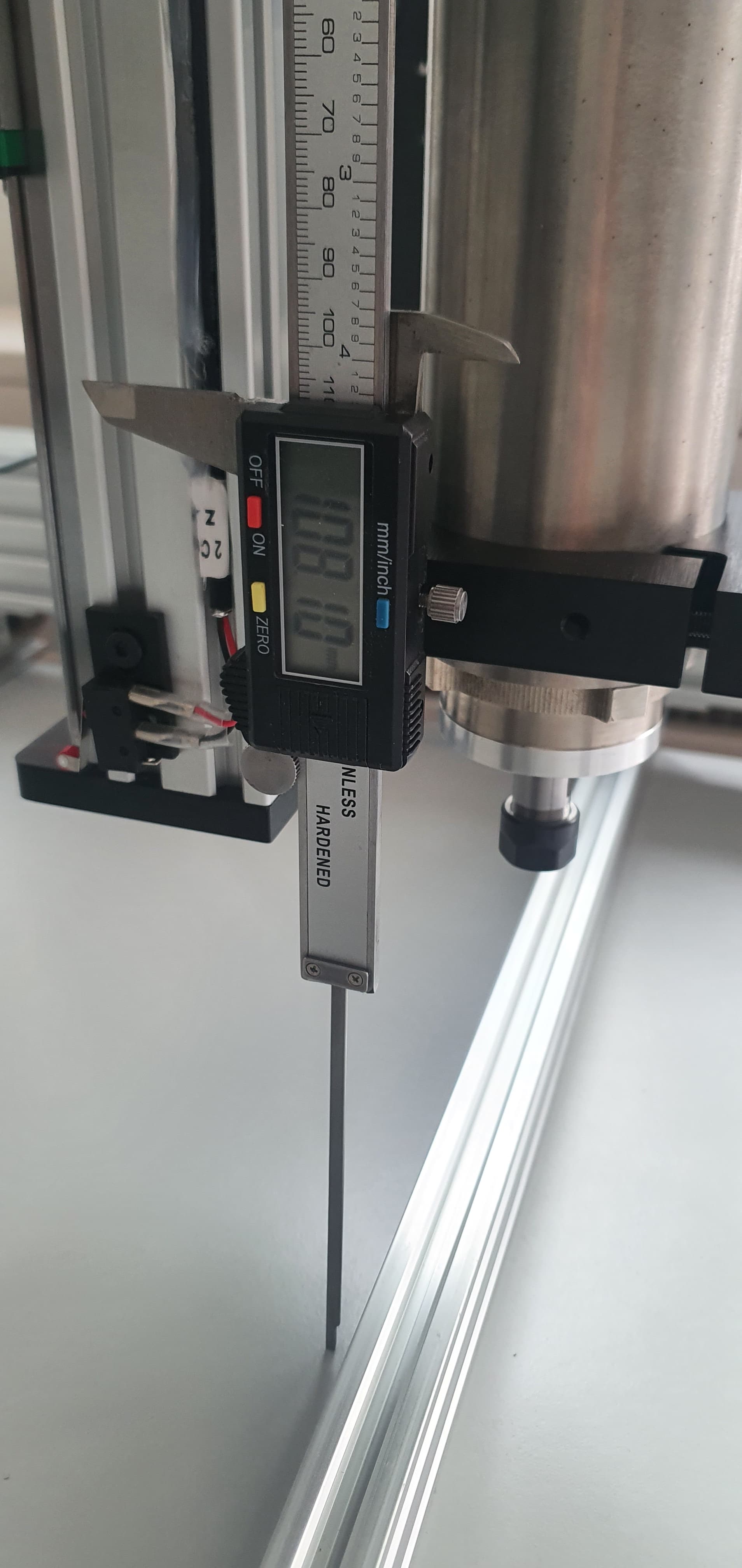
I tried to adjust them by measuring with the caliper.
If you are certain that this number should be integer then perhaps this is due to inacurate measurements.
Are you sure that this should be an integer due to ball screw technical design?
As for the spindle it is VFD and this is connected using RS485 serial connection.
I need to read more about it.
As for Bulkman 3D it’s a Chinese company, they should have some sort of support. I will ask them, they might have those data.
But it is a little bit weird. I’ve watched some guy on YouTube making the assembly of their machine.
He used for all the axes steps per mm=400. But in my case only the Z axis have this number. Other axes are bigger and it is visible at first sight.
I don’t know your ball screws, so can’t give you a value. You should be able to find documentation about the screws that spell out the pitch. One turn should move a given distance, and with your stepper and microstepping settings you’ll know how many (micro) steps for one revolution. Then you can calculate the steps per mm.
@ttraband@ddbuster@timonjkl and others (can’t put more users, but thank you all)
First of all I would like to thank you all in helping me.
I believe I am very close to my first cutting operation at my CNC machine.
I’ve set up some task in Fusion360, used some posprocessor to make the gcode.
Machine is moving in right directions, spindle is spinning.
I’ve got one issue.
My home position of the Z axis is above the waste board, about 160mm.
When I start the gcode generated by Fusion 360, where I set the beggining of my coordinate system at stock - machine goes and starts cutting mid air. Like it would go by maybe home coordinate system.
This is the beggining of the g-code:
"
(Made in : Autodesk CAM Post Processor)
(G-Code optimized for Autodesk controller)
(OpenBuilds CNC : GRBL/BlackBox)
(Post-Processor : OpenbuildsFusion360PostGrbl.cps V1.0.30)
(Units = mm)
(Drawing name : CAM_DECK_CUT v4)
(Program Name : 1001)
(1 Operation
(1 : Pocket2)
( Tool 1: Flat End Mill 3 Flutes, Diam = 3mm, Len = 12.00mm)
( Spindle : RPM = 12000)
( Machining time : 17 min 9 sec)
Again, the volunteers here will give you their best effort, but I believe you’d be best served by relying on your vendor for this support.
Have you used a g code reference site to track what each command is doing? For supporting folks on these forums I tend to look at the Marlin g code reference, since that’s what the V1 firmware is based on, but any googled site should get you info on the standard commands.
I’m a little surprised to see multiple commands on a single line (G90 G94 G17), but can’t say if that’s truly a problem. I’m not familiar with the G17 command, but seems to make sense if you’re doing a surfacing operation (at least as far as my google-fu leads me).
There’s also a Z1.3 line - this looks to me like a Z parameter with no command - should that have a G0 or G1 preceding it? Just before this line, it moves to Z15, so that makes sense with the observed behavior.
I’m also not very familiar with the G10 command, looks like it’s for managing a permanent offset, rather than a temporary position adjustment. I would think you’d use this if you were always going to fixture a part at the same location relative to the homing location. I don’t do enough repetitive work for that to make sense for me.
Most folks on these forums reset the origin with a G92 Z0 with the tool touching the very top of the work piece, or a G92 Z0.5 if they’ve touched-off using, for example, the .5mm thick “Tiny Touch Plate” from the V1 store. You can also include X0 and Y0 in the G92 command if the tool is at the desired 0,0 coordinate.
From my quick research, it appears that G92 is temporary, in that it is expected to be lost when the controller restarts, whereas G10 may be expected to be permanent, but I’d expect that may vary by controller.