I’m wondering if this CNC router would be good for making cockpit panels. The panels I want to make consist of a back 3mm thick clear acrylic and the front 2mm thick White acrylic or Romark. I would need the router to cut the panels as well as holes. The front would be painted and I would use the router to etch the lettering. Would this type router work for this type of application? I’m also wondering how I would hold the panels in place to do the etching.
I’ve used tape sold on Amazon as ‘wood working tape’ to hold things down with good results, it’s said to be strong enough to hold blanks to a lathe faceplate for turning.
As this is posted in the Lowrider category, I’ll note that I think the MPCNC would be better than the Lowrider for cutting panels like this. It might work to cut the panels and cutouts for all the pieces at once, but it would probably be best to do the engraving of each panel seperately, at least.
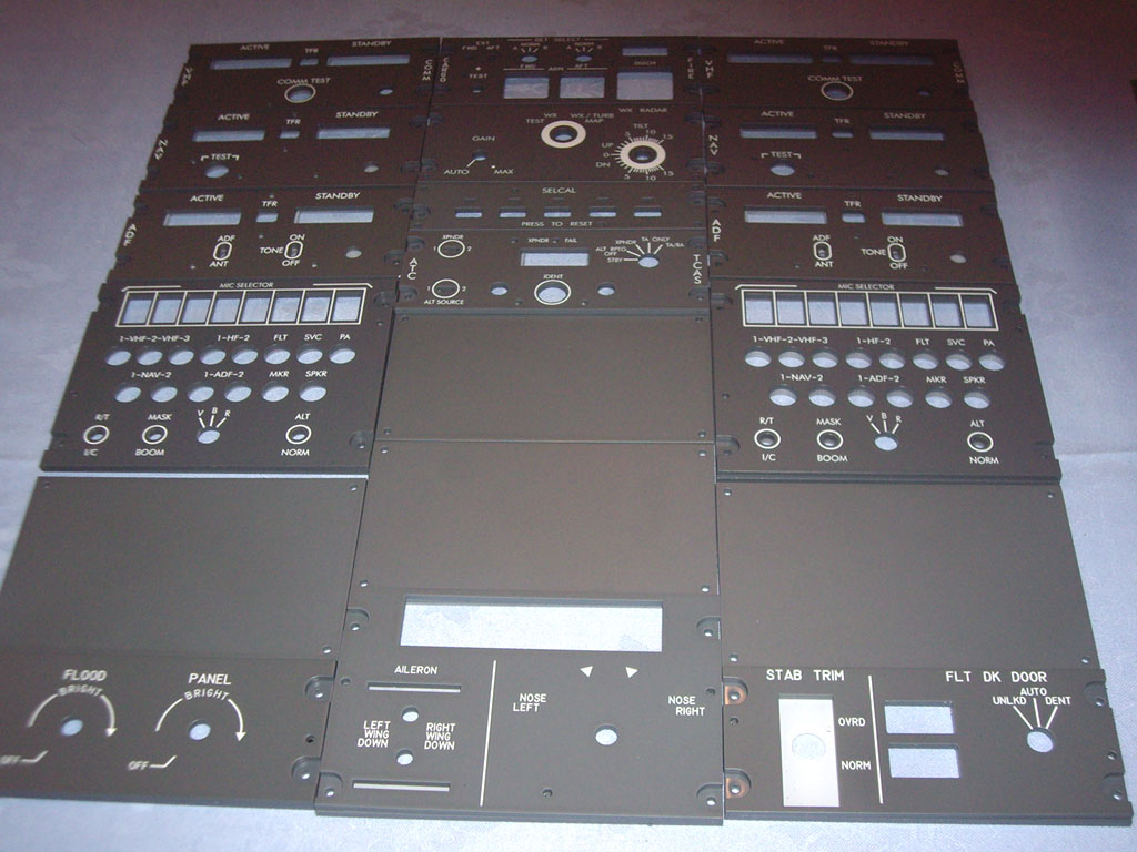
My question is…Dual ADF receivers? Really!? Nobody actually navigates with those anymore, right? I could see keeping one as a AM radio receiver, but TWO? 8^)
I think either machine would handle this well. I’ve used the blue painter’s tape and crazy glue method very successfully and it would be perfect for this work holding.
I don’t know exactly what you mean by etching but engraving all the details would be no problem. There are a few people doing airplane stuff on here and I think I recall someone recently talking about this very thing for a control panel.
I intend to use my MPCNC for making aircraft panels too. In your case I would consider initially using hold-down clamps along the sides to allow you to drill and clear the corner panel mounting holes. Then use these holes to hold the part down for the rest of the work: drilling the rest of the holes, meter pockets and final edge routing. Last you could do the “etching” of the lettering being fairly confident that the lettering would be in the right place (because you’re using the same mounting holes for all machining).
One of the more challenging aspects of any kind of milling is choosing the best order of operations, especially when you may have to remove the part for steps that are not done on the mill.
Even if you want to use the “tap and glue” method to keep the parts very flat to the surface, I would still set up the holes for accurate registration for the following steps.
Added note: what ever CAD software you’re using should allow layers where you can put each of the machining steps on a separate layer to help in the selecting of the correct lines while insuring the layers are all lined. It may be too “Noob” to mention here, but it is very basic to most machining steps.
I think your are probably right about that. The largest part I foresee printing is 470mm long and 72mm wide so I don’t require a large cutting space. I have an Anycubic MegaX 3d printer so I plan on printing my own parts for the CNC. I’m holding off on ordering until the Rambo v1.4 comes available.