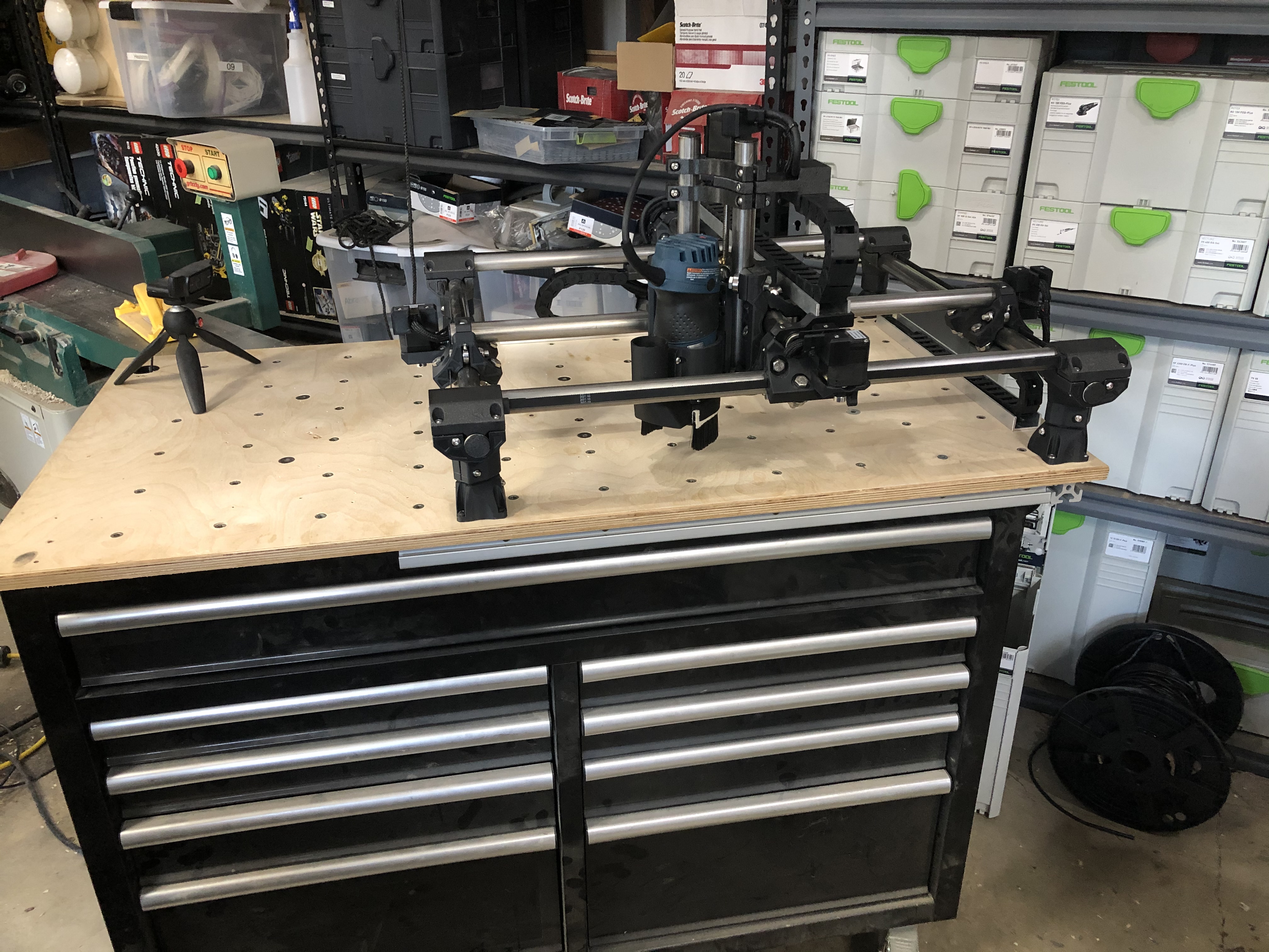
This thread will take me a little bit to get all the details together but I wanted to share my approach for modifying the MPCNC Primo to provide as comprehensive of a walkthrough of how to wire the electronics for the CNC but also how to safely and reliably manage the cables. This has taken me a few months to prototype and test everything. Prior to this I was running an original MPCNC design for several years. It worked ok but had some issues and some of my parts were cracking and needed replacement. When my trim router finally went belly up I decided it was time to rebuild everything.
Presented here is the, mostly, final result of my efforts except I still am waiting on some barrier terminals and a new usb-c cable so I can finish the electronics cabinet. My modifications have been adapted along the way from ideas I found in multiple places. In the end, I modeled and built everything from the ground up. I don’t remember some of my original sources so forgive me for not citing them. The one exception is @randysteck as he and I are friends in the real world. He is largely responsible for getting me into the cnc and 3D printing world and I drew inspiration from his original cable mount that attaches to the stepper motors.
In the next few posts I will go through some of the design and modification details. I will eventually include all of the 3D files so you guys can use them if you find this helpful. I will also include a tutorial on the physical wiring of the machine at some point as that still has a lot of missing details in the assembly instructions.
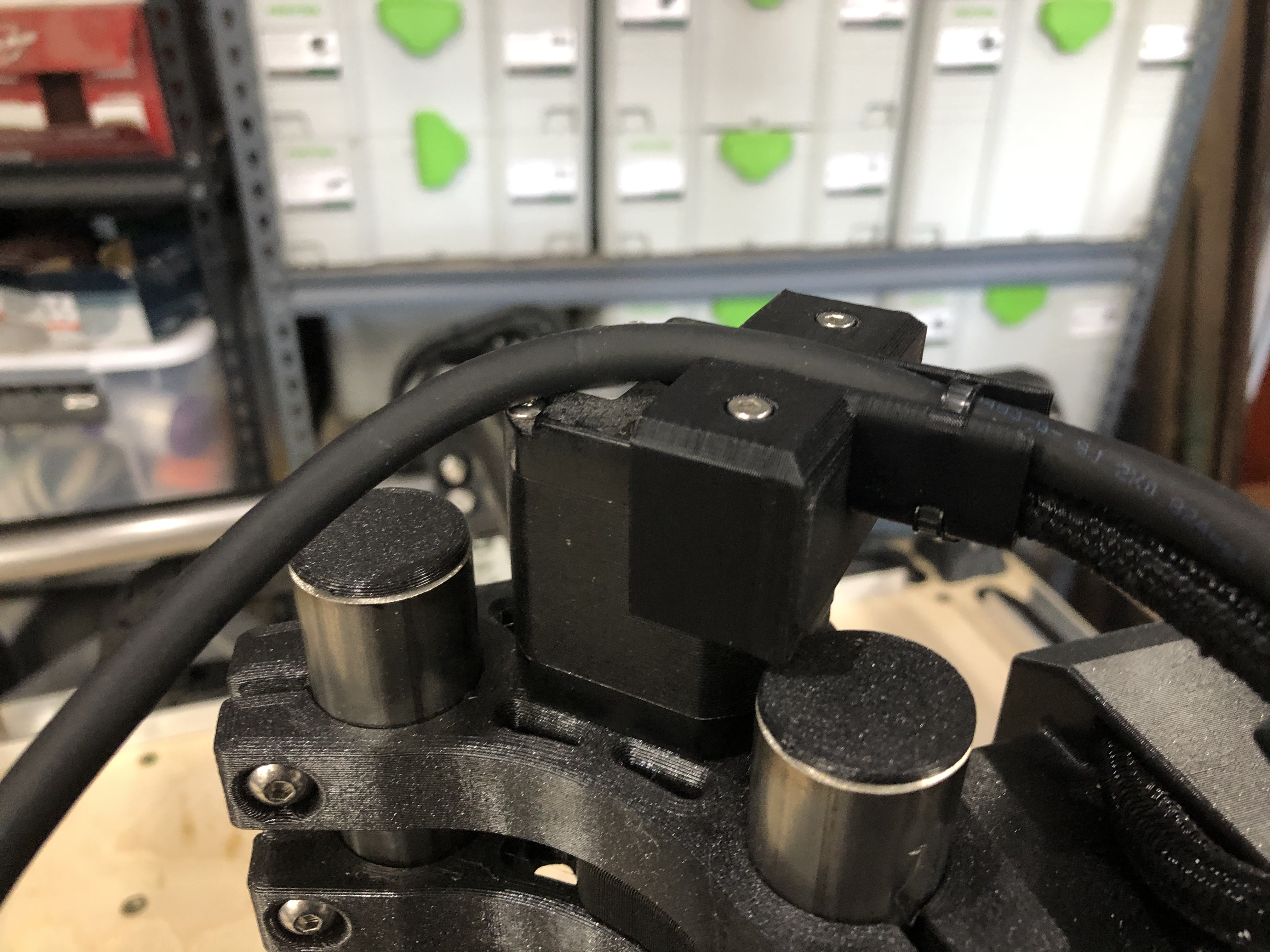
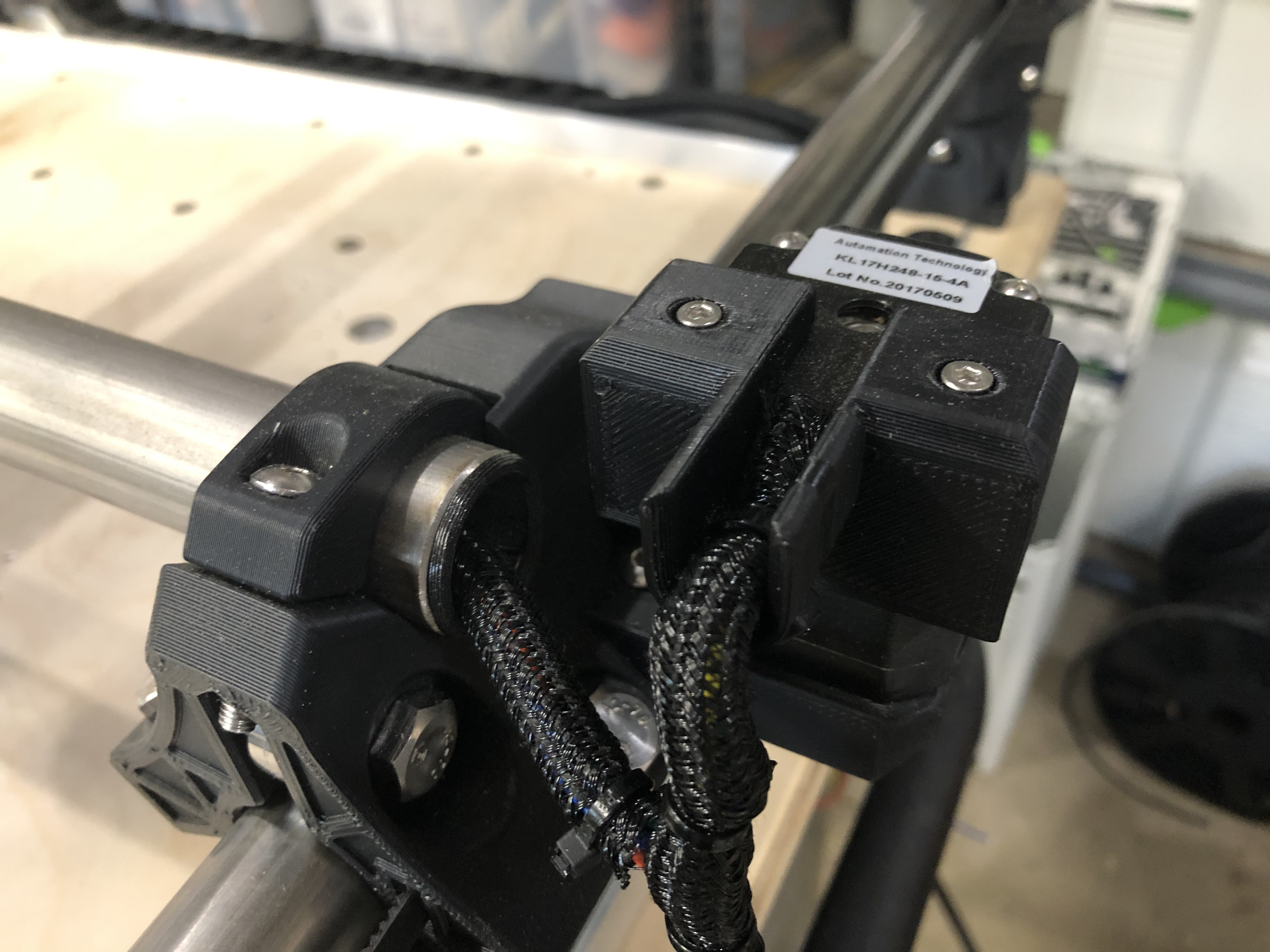
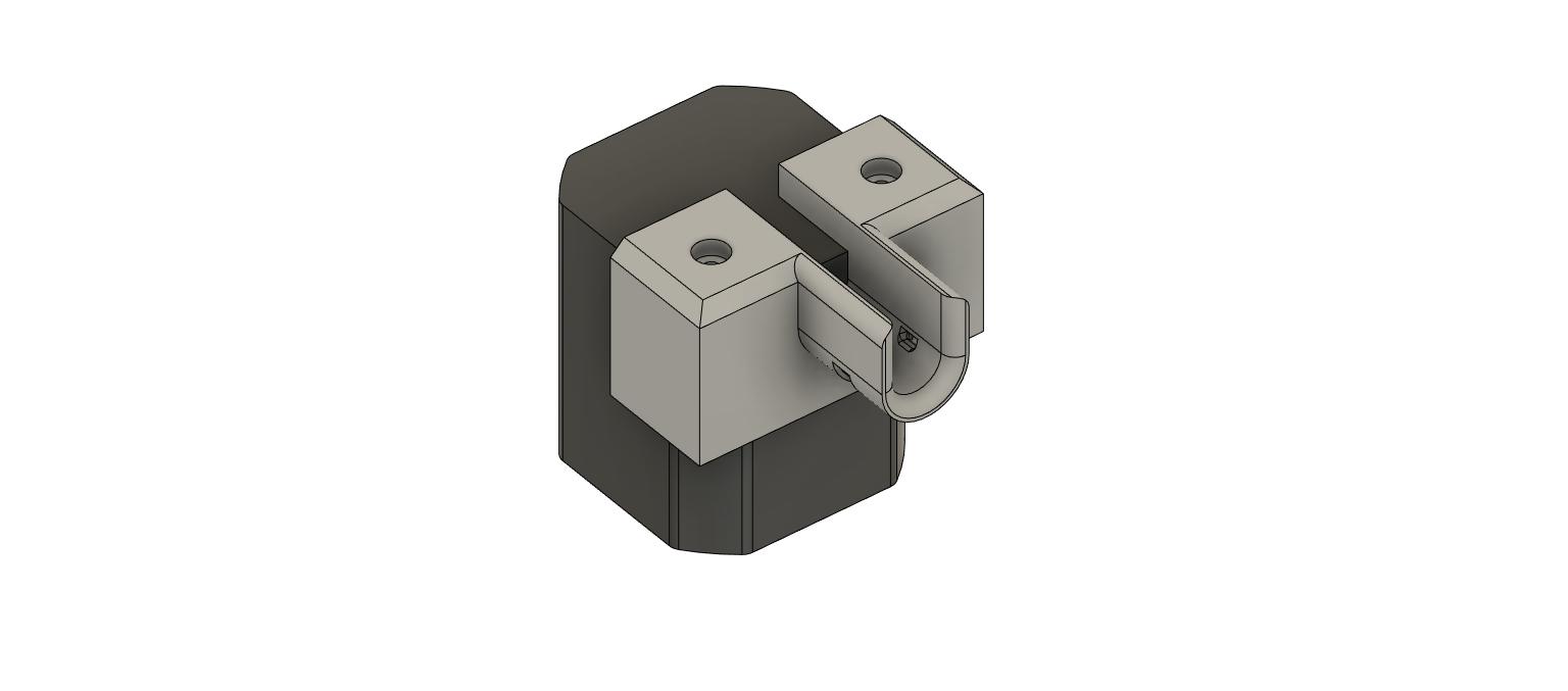
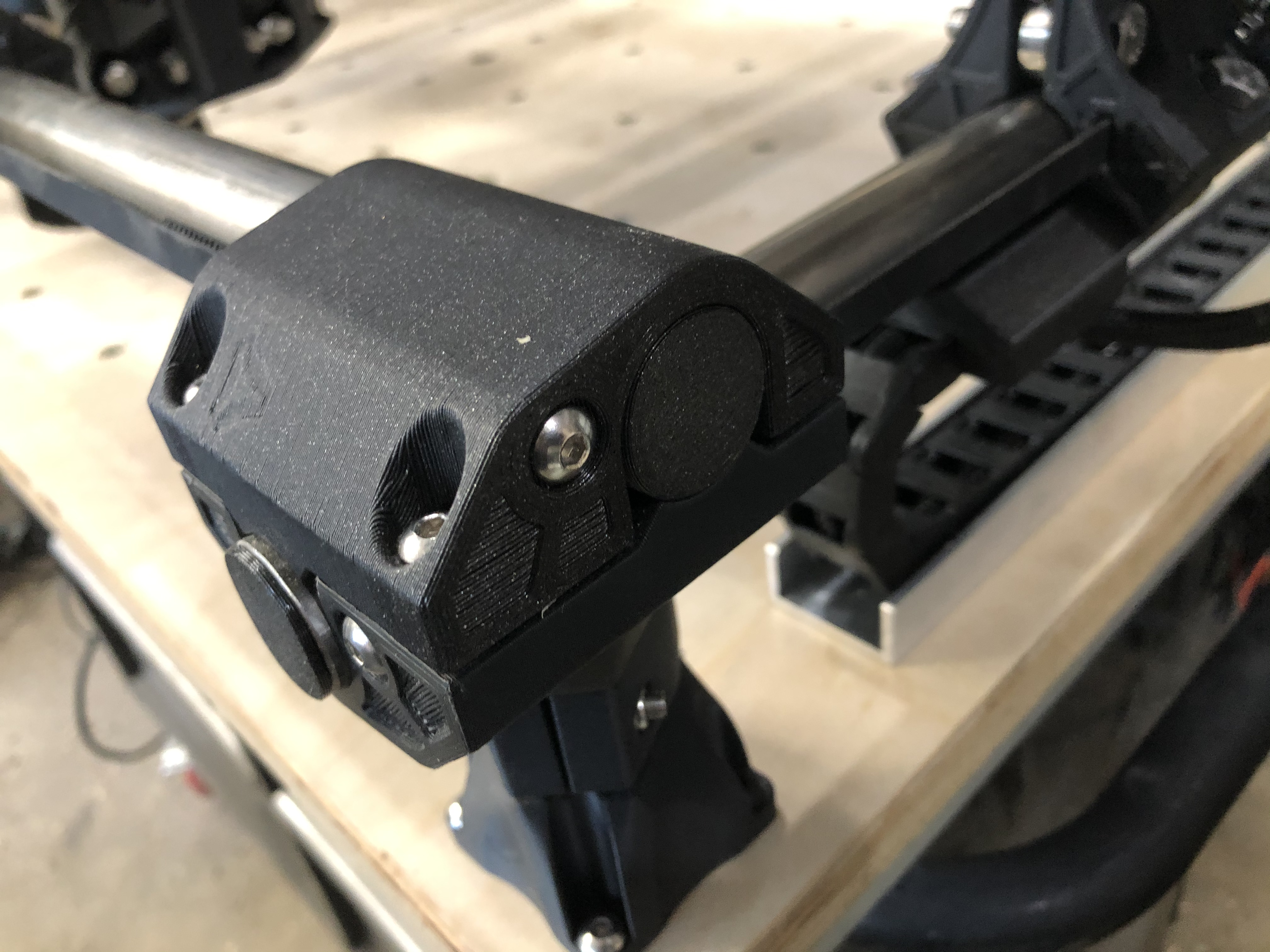
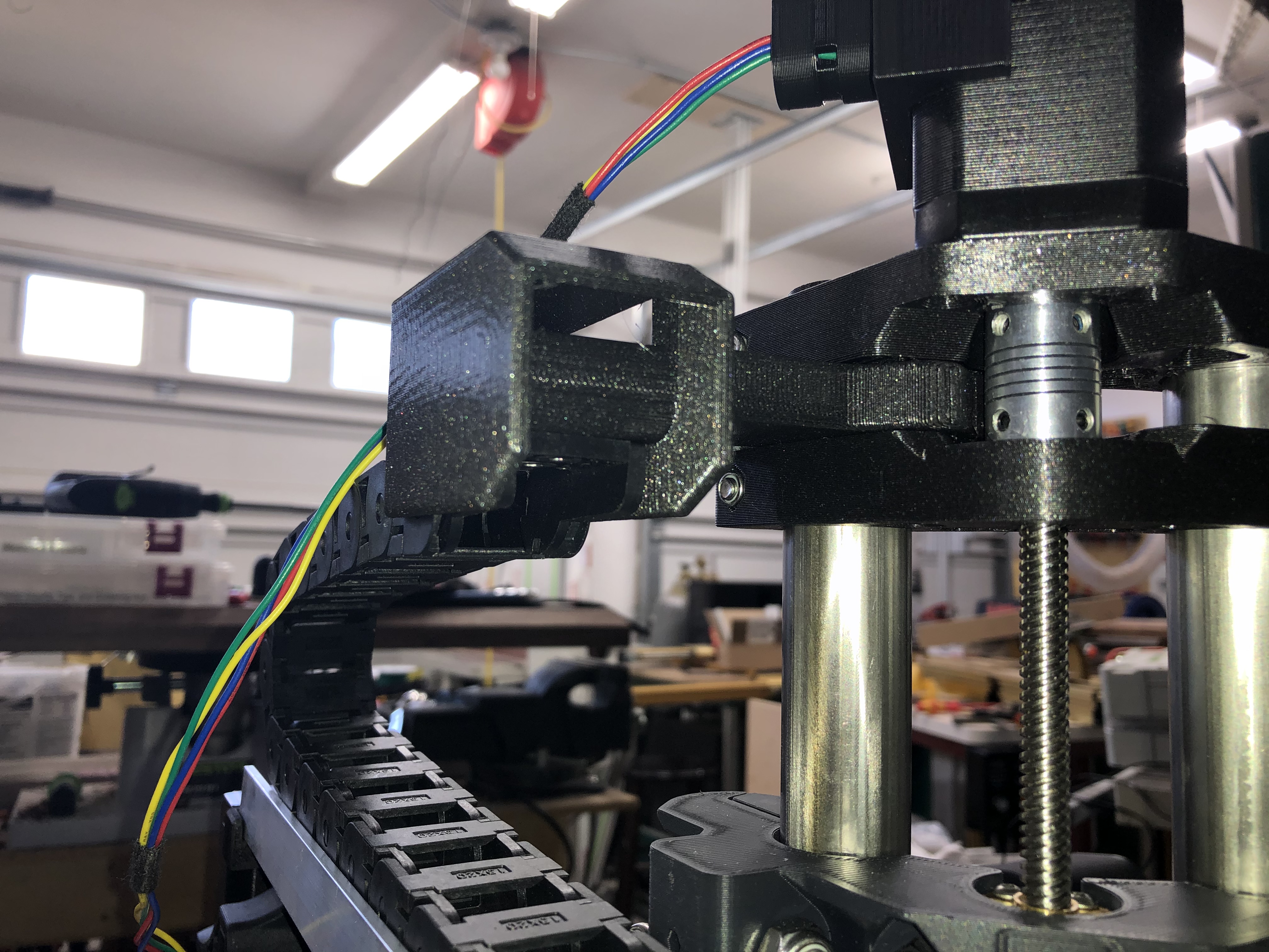
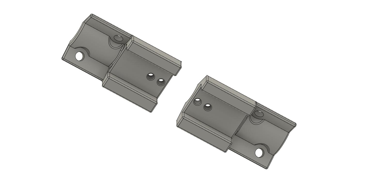
The first feature I will zoom in on is the cable mounts and strain relief at the steppers. @randysteck came up with an excellent original design where he attached the mount to the stepper motors with zip ties. I modified this a bit and ended up building a new design that attaches by replacing two of the original screws on the stepper motor with longer screws that are used to mount cable support. I also changed the zip tie mounting to allow the device to act as train relief and to secure the cable cover if you are using one.
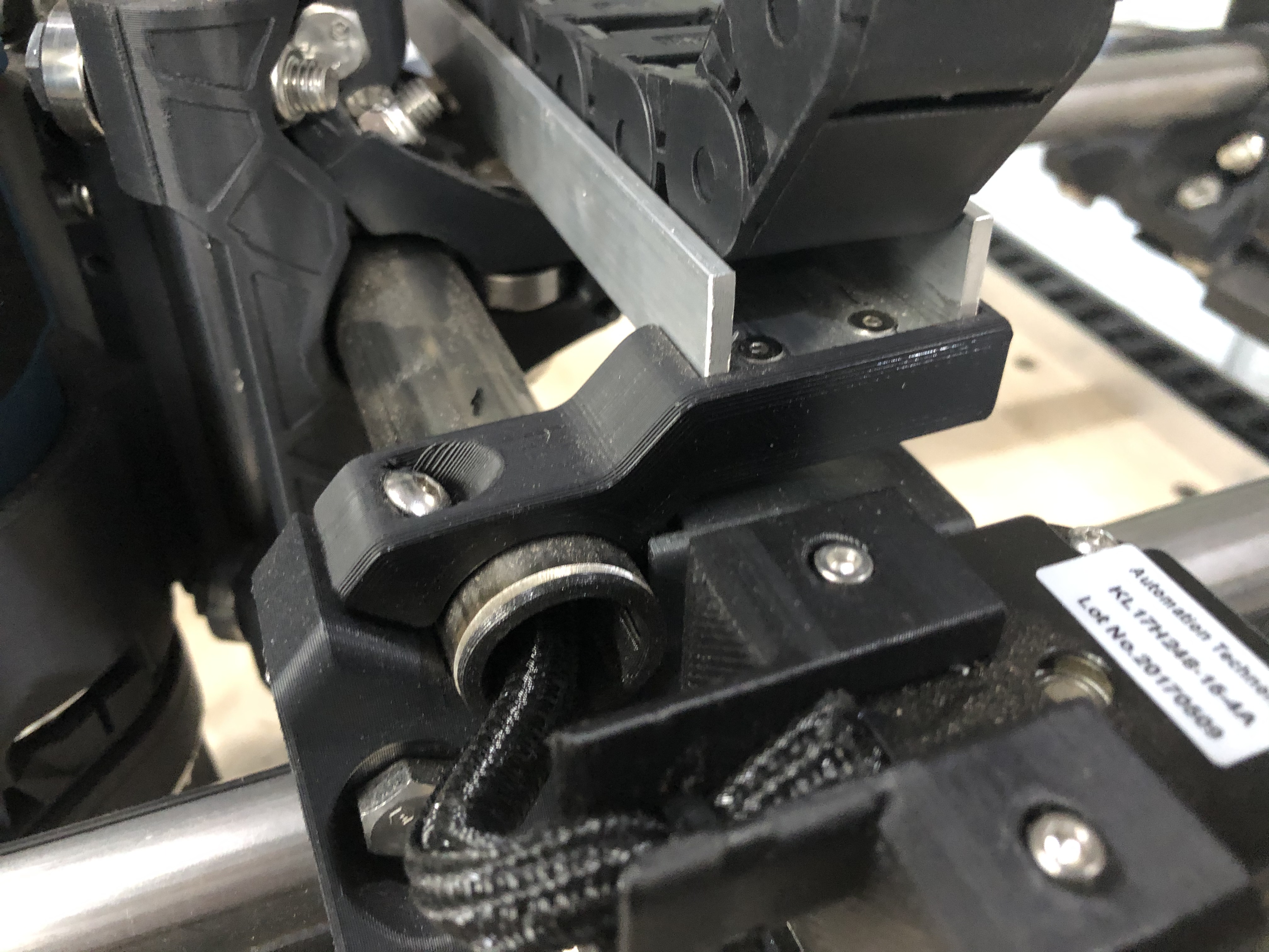
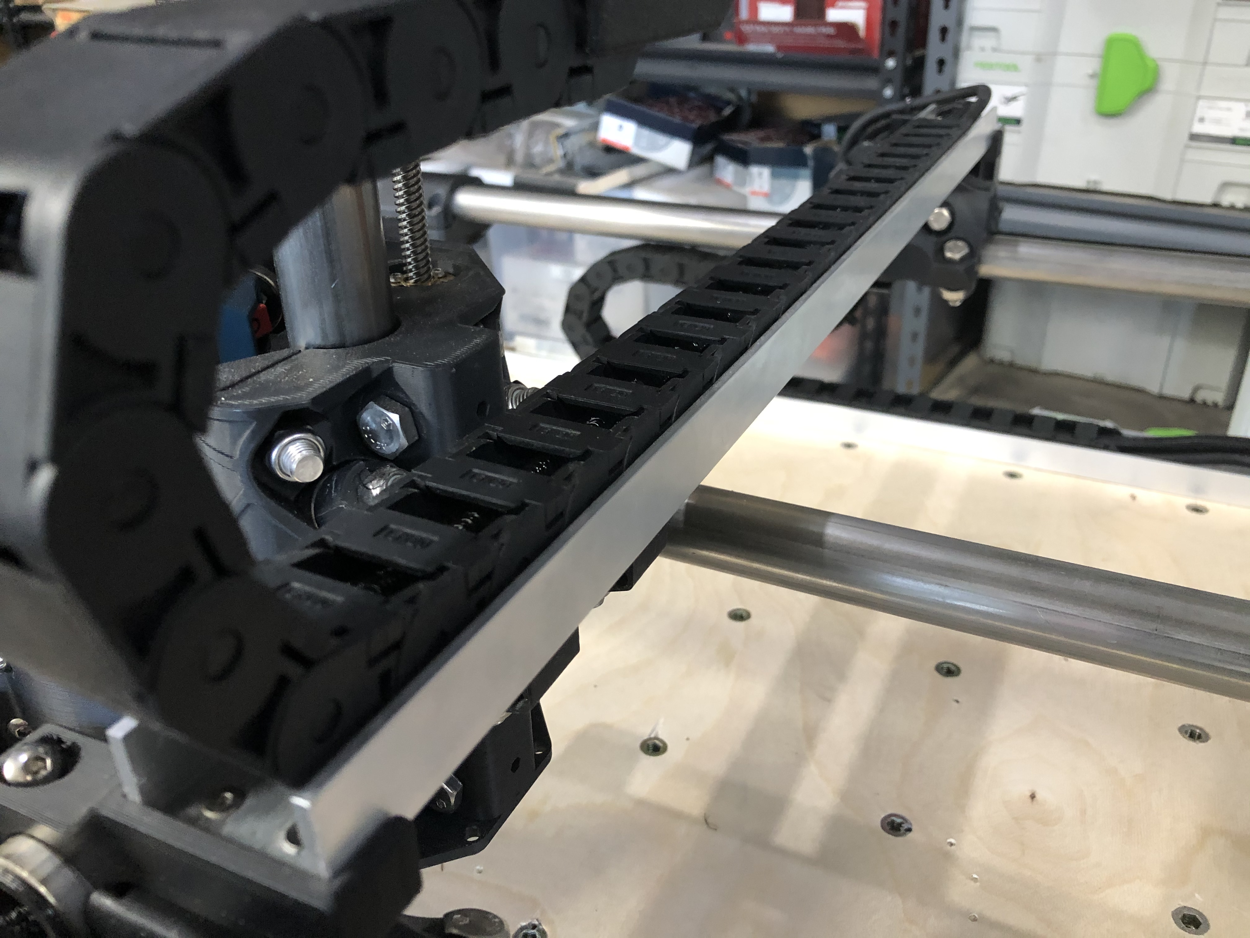
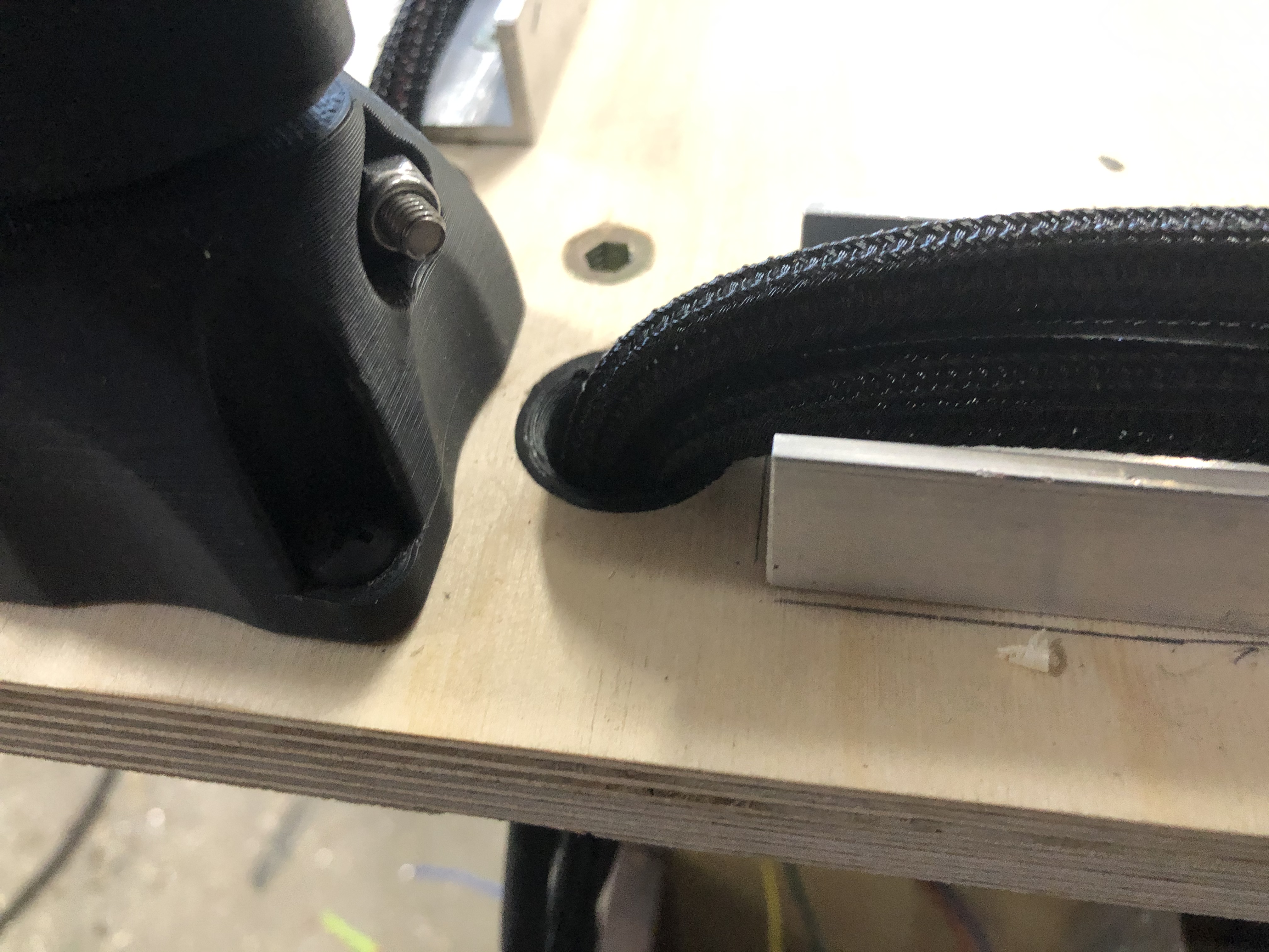
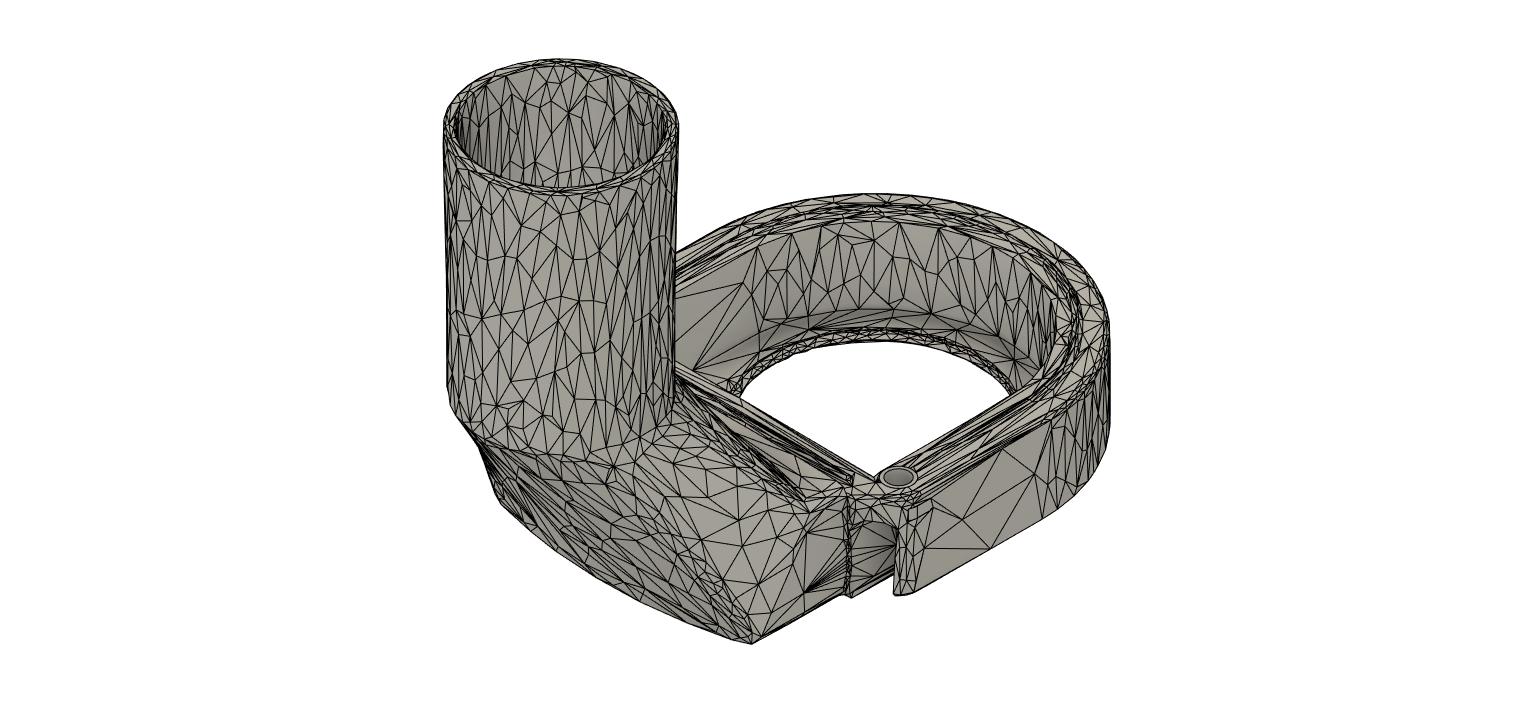
The next feature is a modification of the stock tubing clamp for the x-axis. This is intended to work with an aluminum U-channel. I will come back and edit this in the near future to add the specific parts used for this. All hardware was purchased at McMaster of Puppets Carr except the drag chains, they were purchased from Amazon.
8 feet of this aluminum U-channel was enough for me for the entire project. My MPCNC is the minimum size though, you may need more based on your machine size.
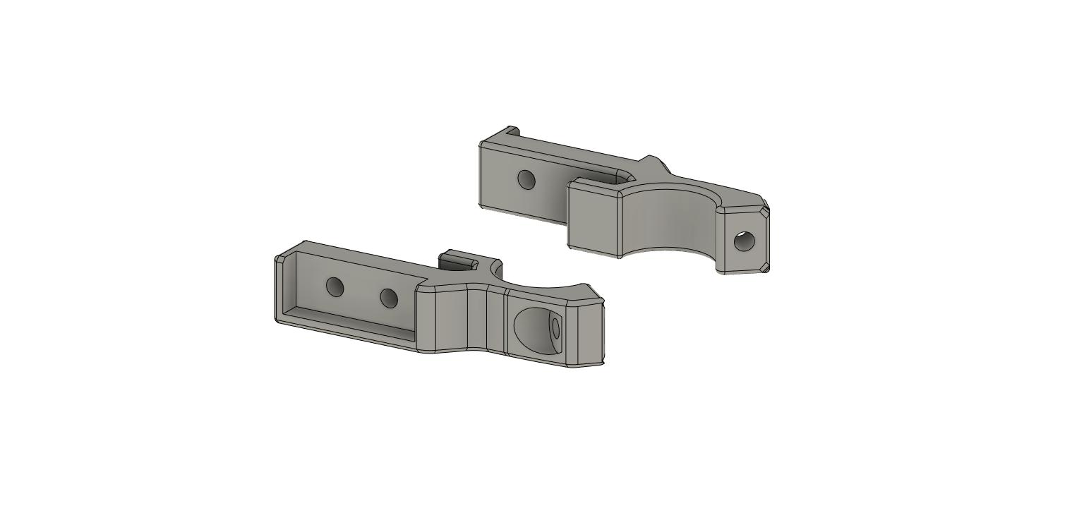
Assembling everything is pretty easy, just print the brackets instead of two of the stock tube clamps. I used PLA with no supports. The same hardware is used as stock to attach the bracket. The U channel will need to be cut to length. Position the lower end of the drag chain where you are comfortable, drill and tap the U-channel and use the M4 x 8mm flathead screws to attach the lower drag chain to the U-channel.
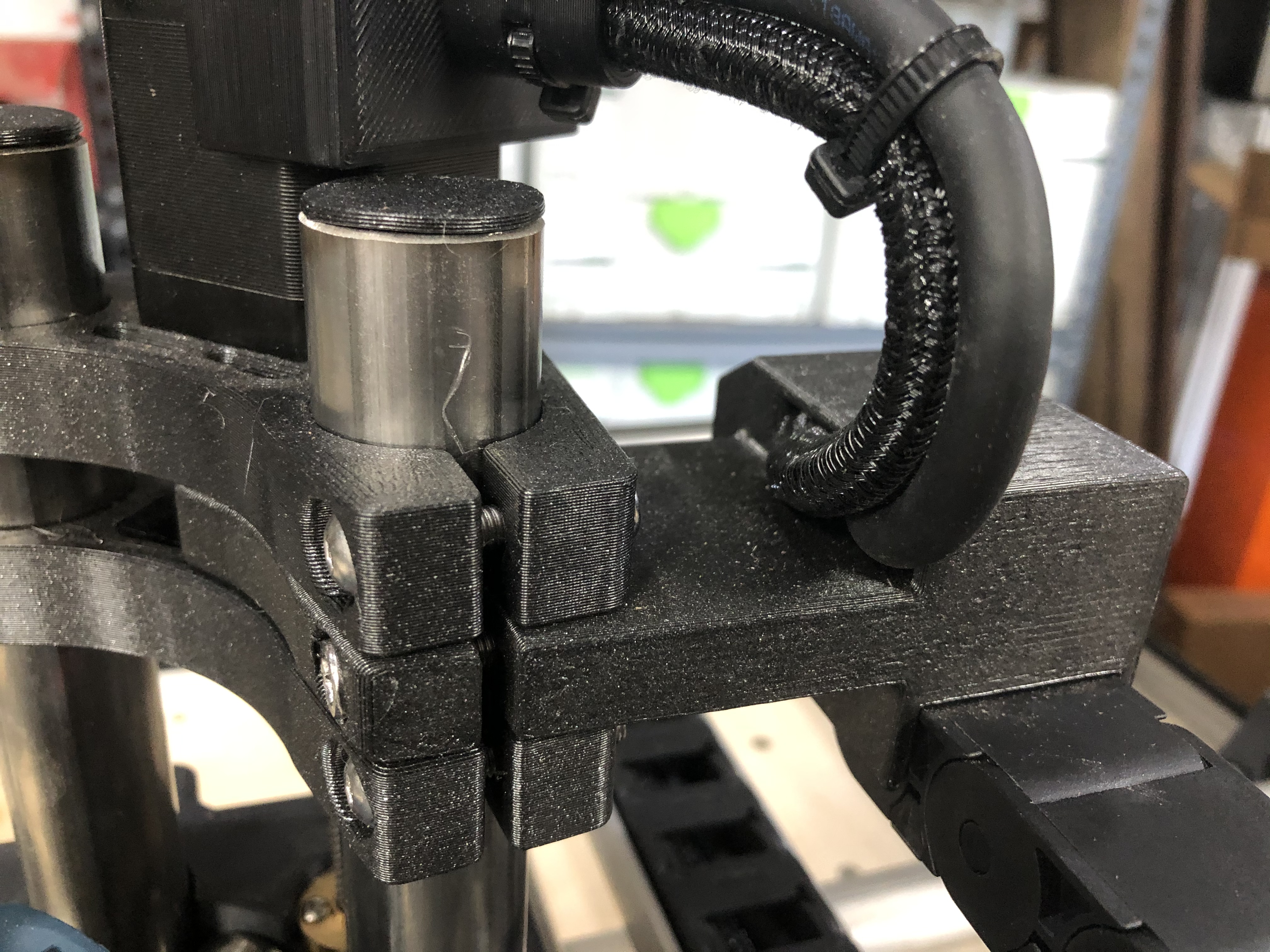
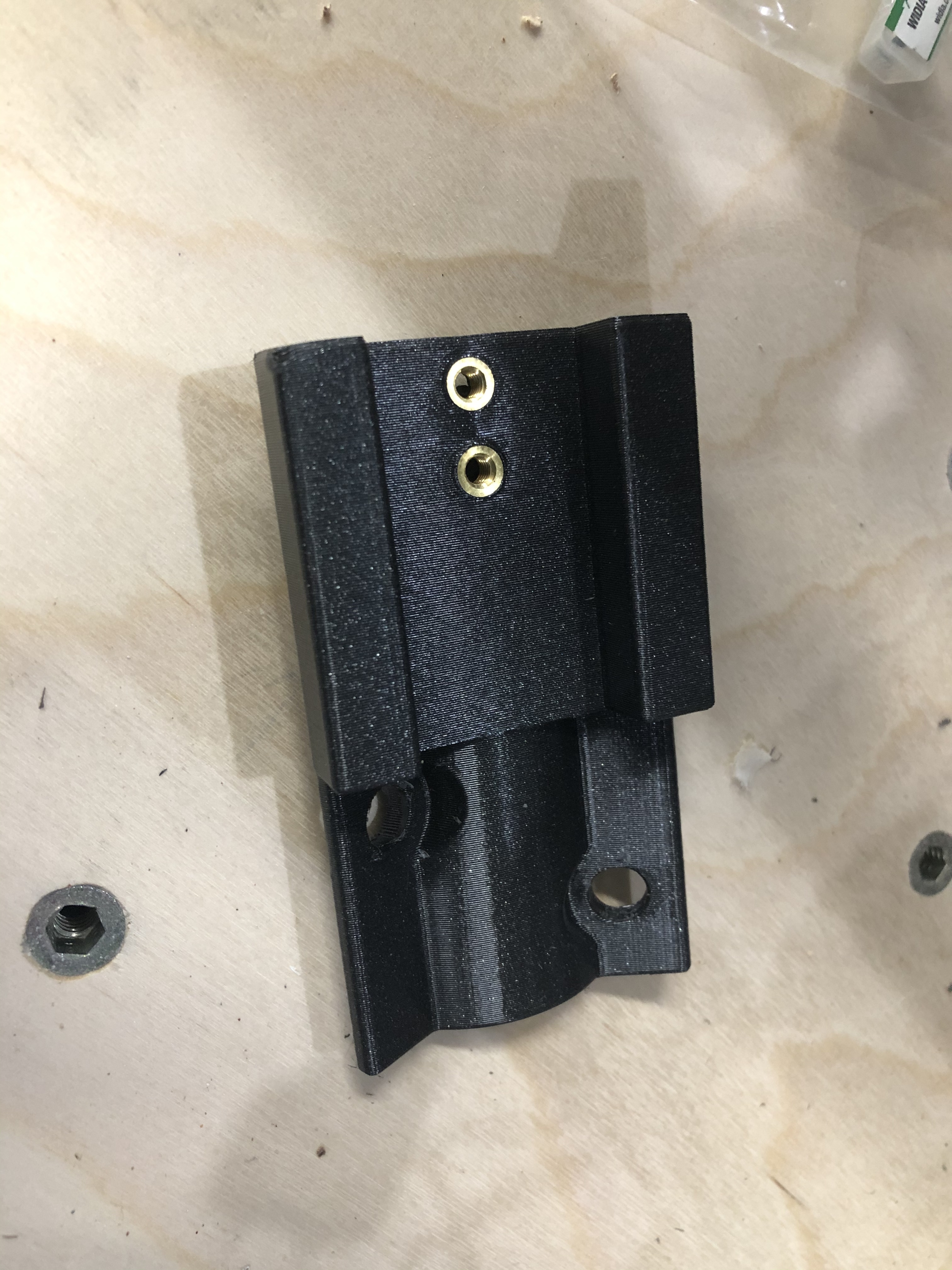
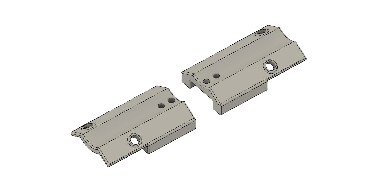
The upper drag chain mount took me several prototypes to figure out. This design seems to work pretty well although I may be able to improve upon it further depending on how motivated I am.
Printing this is pretty straight forward, PLA with no supports, I had success printing it on the long flat side closest to the camera on the lower render.
Hardware:
M5 x 30mm socket head screw The socket head screw has to be used here instead of the button head screw that is used everywhere else because there wasn’t enough room for the latter.
M5 lock nut. This fits into the nut trap that can be seen on the underside.
M4 x 8mm flathead screw to attach the drag chain to the underside of the bracket via heat set threaded inserts. These are the same screws used on the step above.
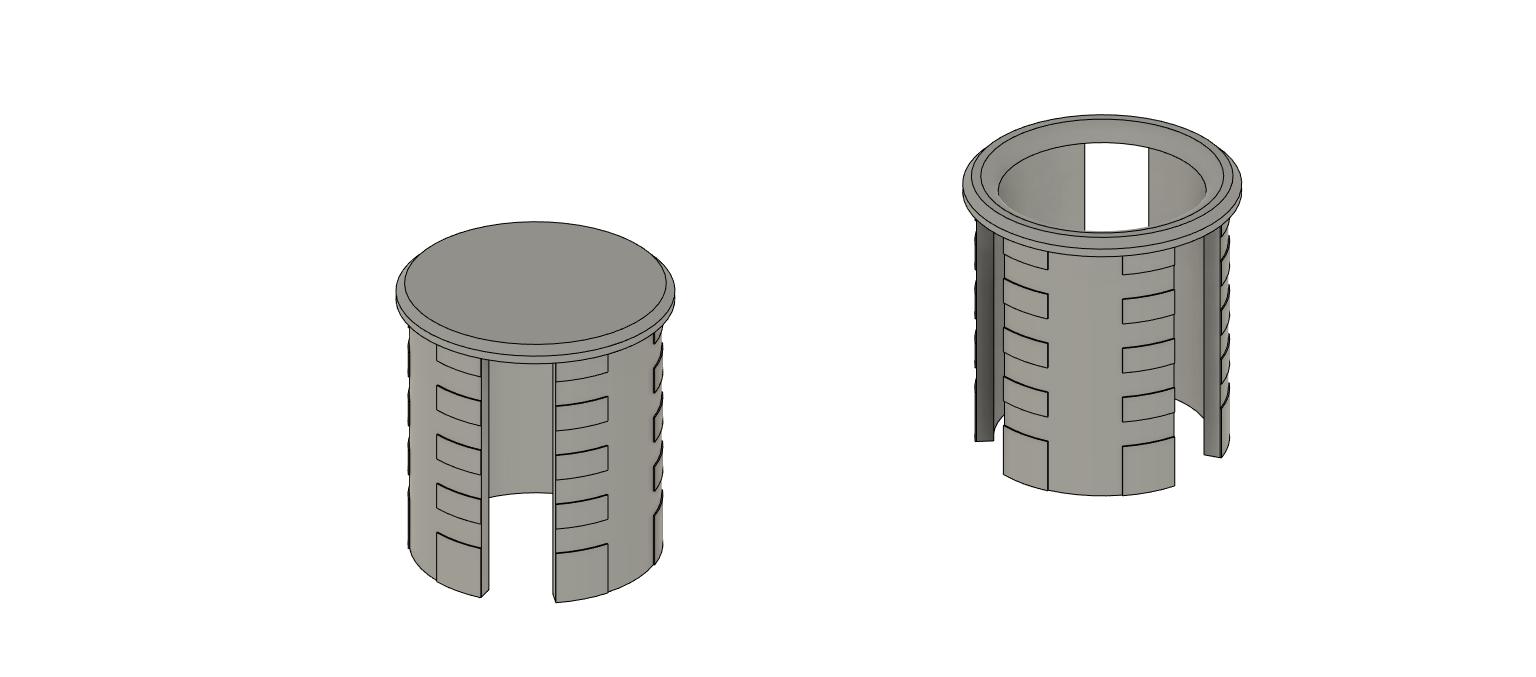
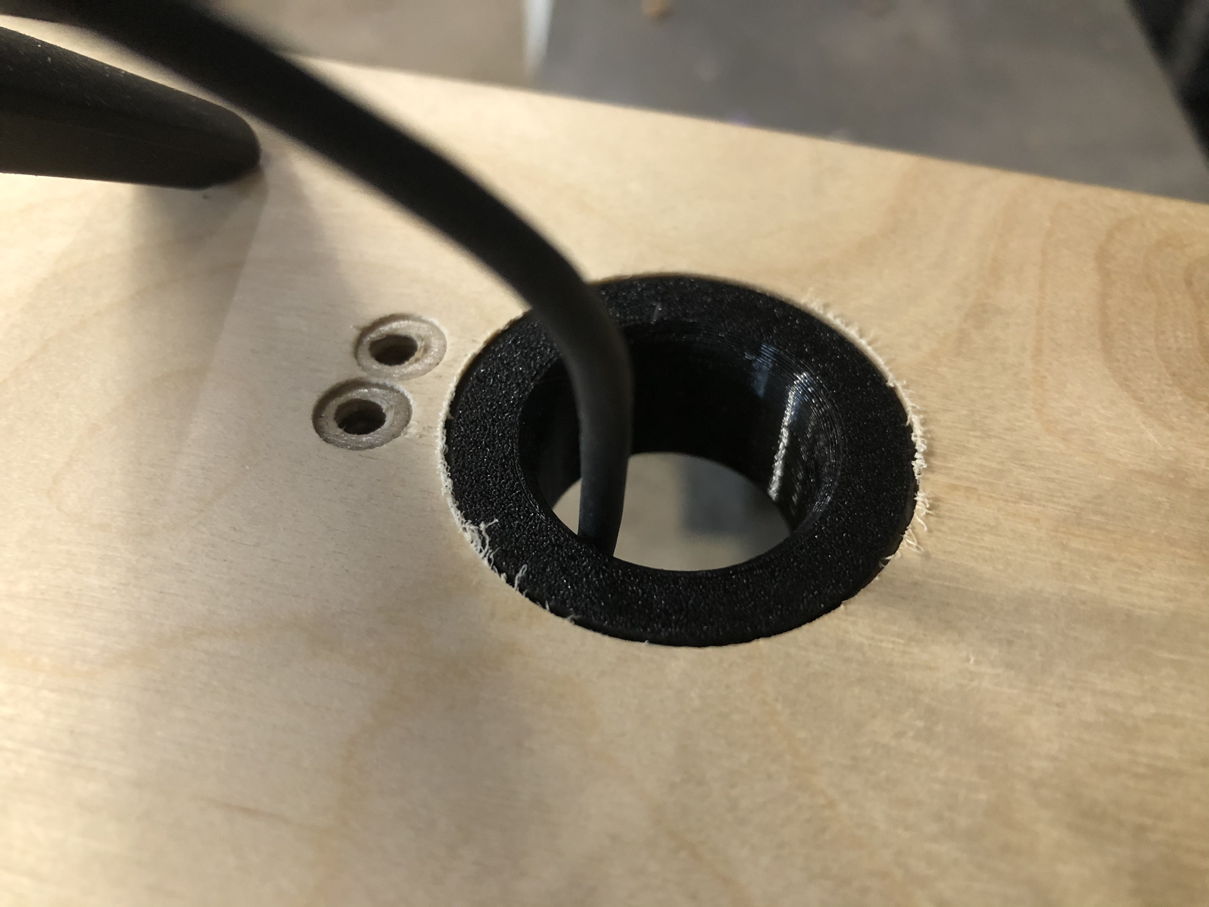
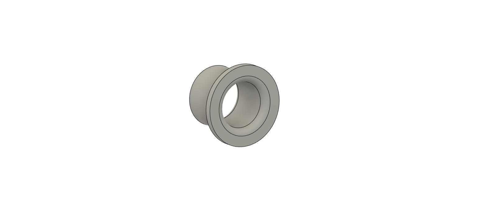
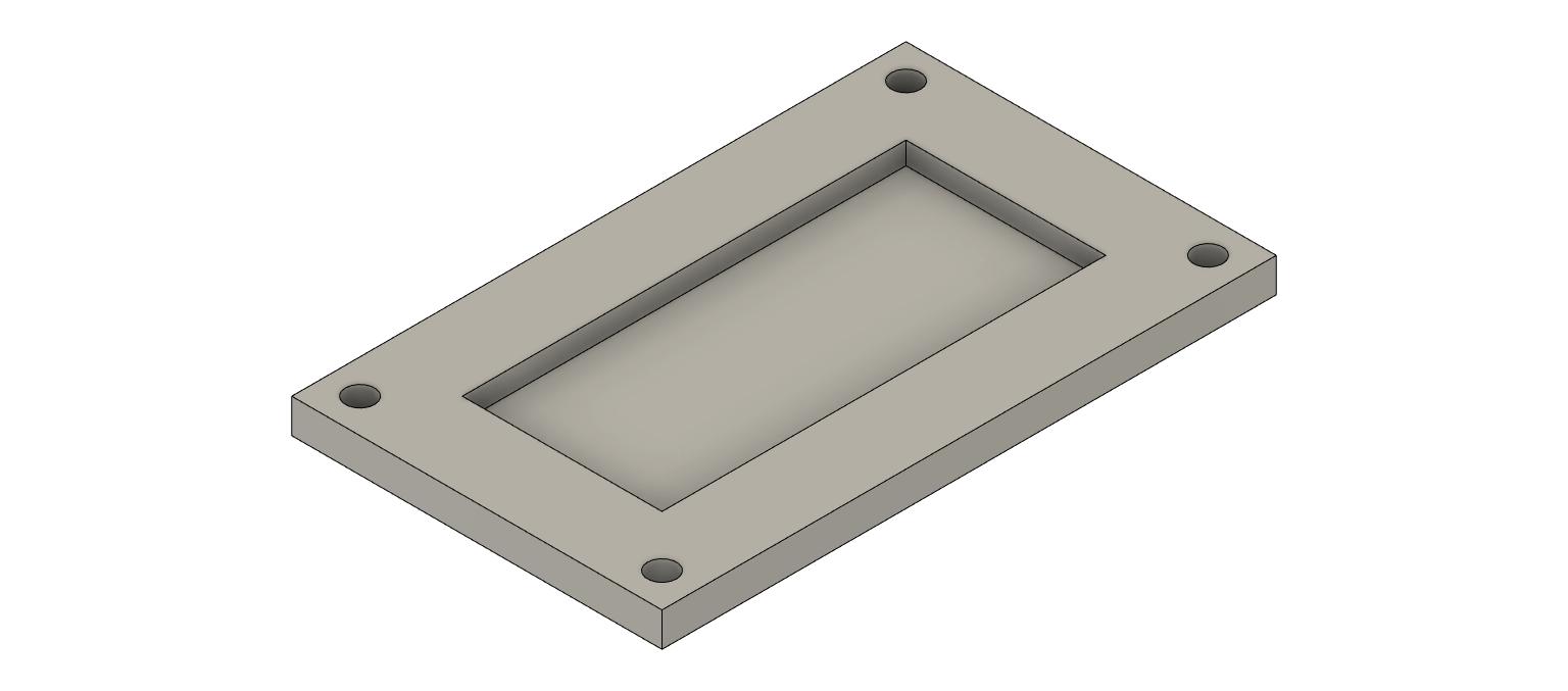
In addition to the tubing grommets I designed some table grommets where the wiring passes through. Nothing crazy here, but for the sake of being complete I will include them. In the first photo below don’t pay attention to the extra two holes, I reused this board from my original MPCNC and this was the old drag chain mounting location.
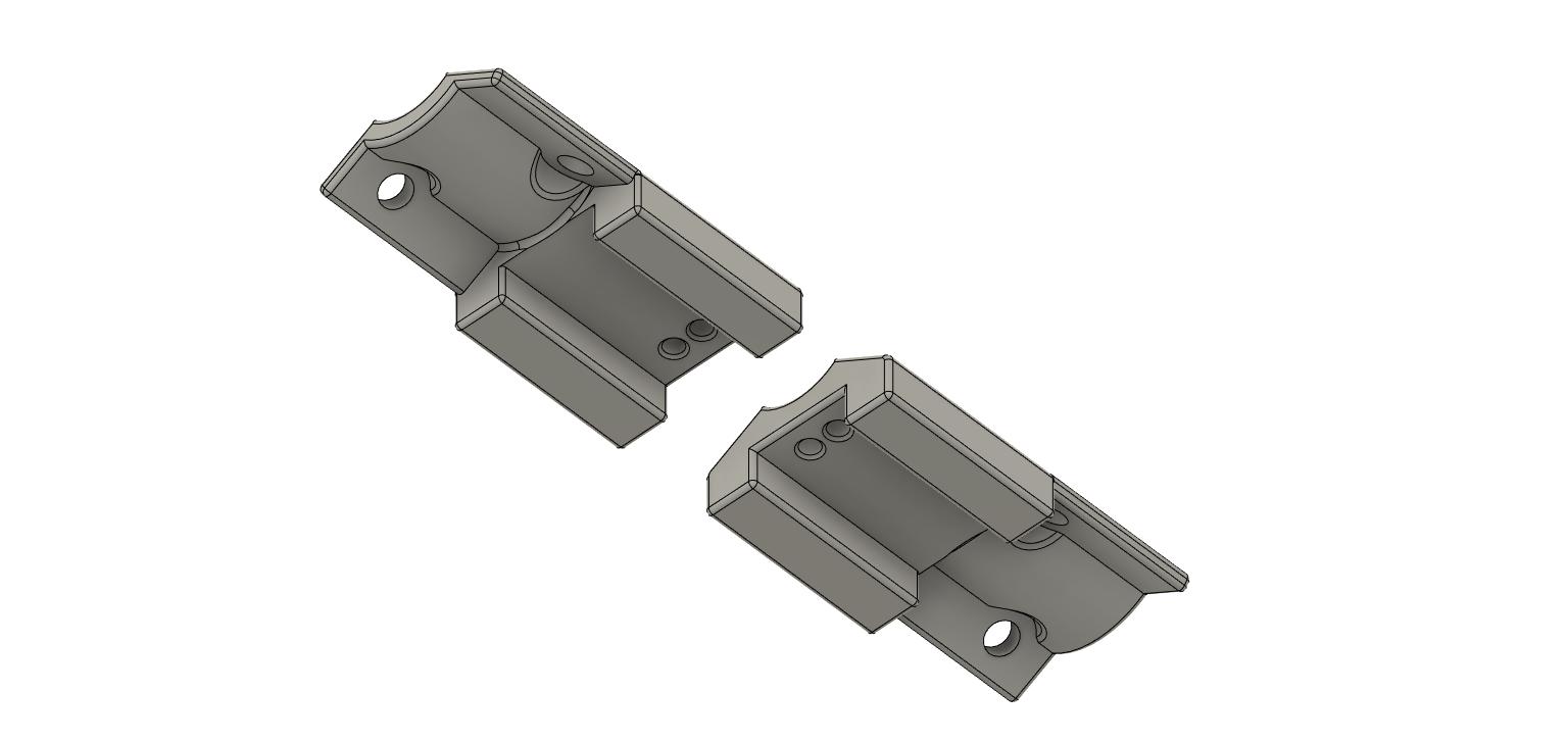
The other feature that was somewhat of a challenge and required multiple prototypes to figure out was the lower drag chain mounts. There are actually two separate designs here because I had to use two different drag chains. For the MPCNC minimum Z height, which I used here, I could not fit the larger drag chain under the lowest rail. I reused my old, smaller drag chain and, as a result, had to redo the mounting points for the unit as they are different. Overall pretty simple modifications. In the end, you can customize the lower mounts to match your use case.
I would not recommend using the smaller drag chain I did though. It’s a pain to use because the top doesn’t open to run the cable though like it does in the larger ones. Again, links to everything will come.
M4 x 8mm flathead screw to attach the large drag chain to the underside of the bracket via heat set threaded inserts. These are the same screws used on the step above.
Smaller drag chain (I don’t recommend this one but it does work just fine for the Y axis that is closer to the workbench).
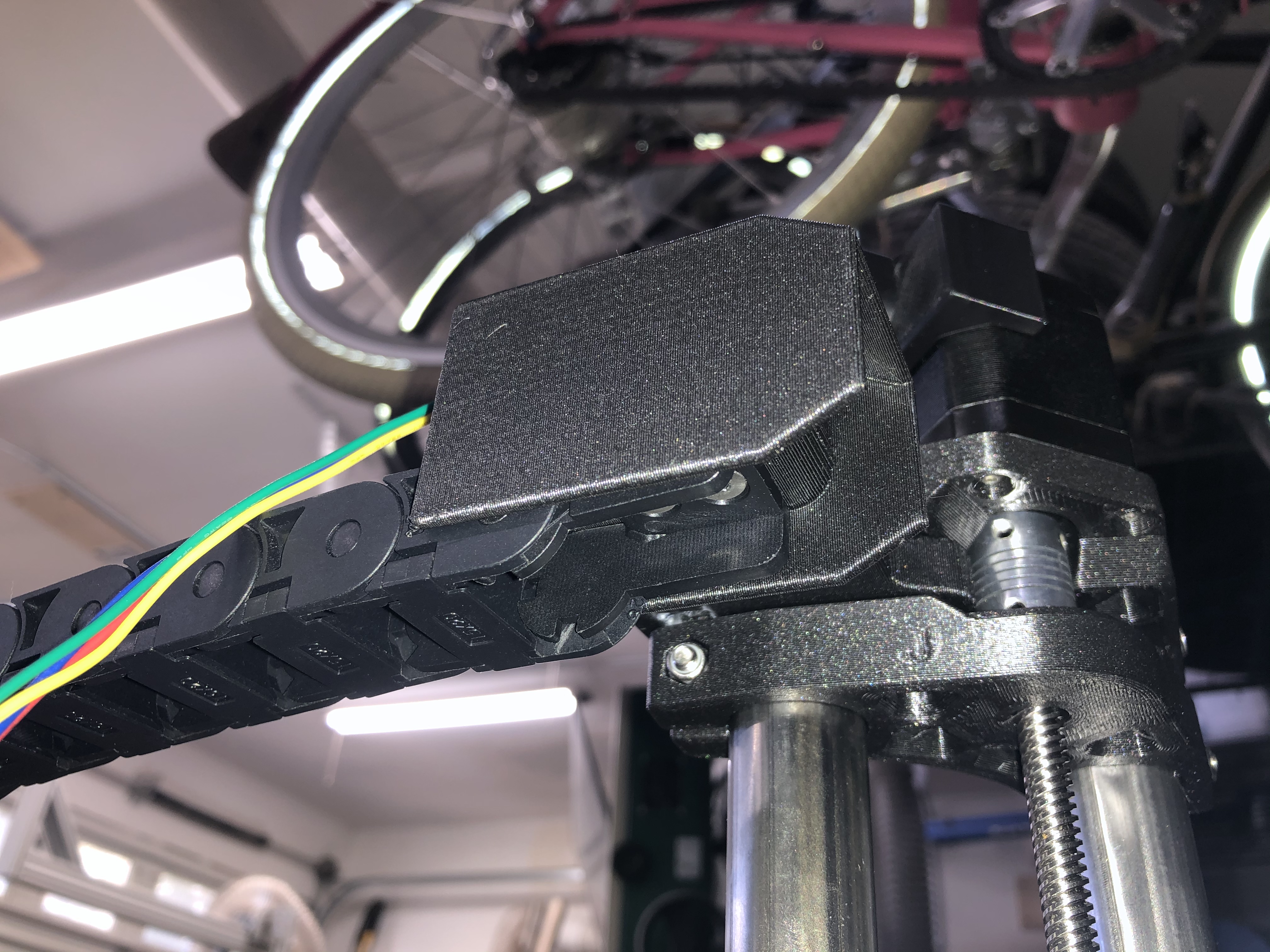
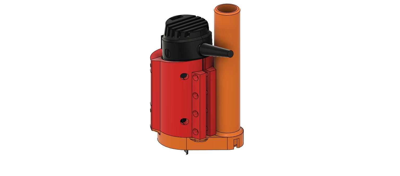
It is worth noting that the drag chain mounts I designed will reduce your useable cut area. This was a non-issue for me because it didn’t reduce the area any more than the vacuum attachment I also printed. The router mount and vacuum attachment is not my design although I did remix the vacuum attachment so it can be secured with screws and threaded inserts.
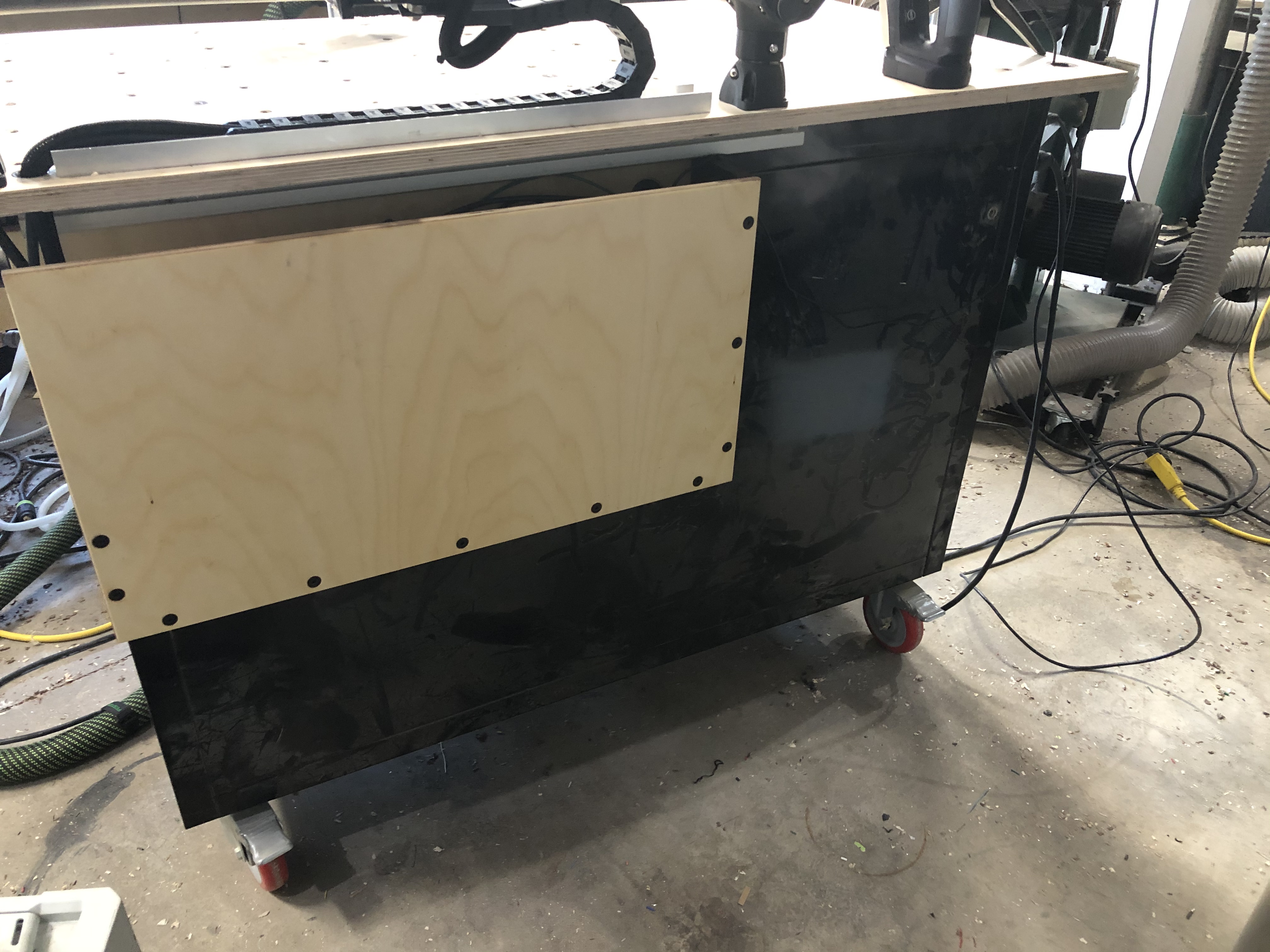
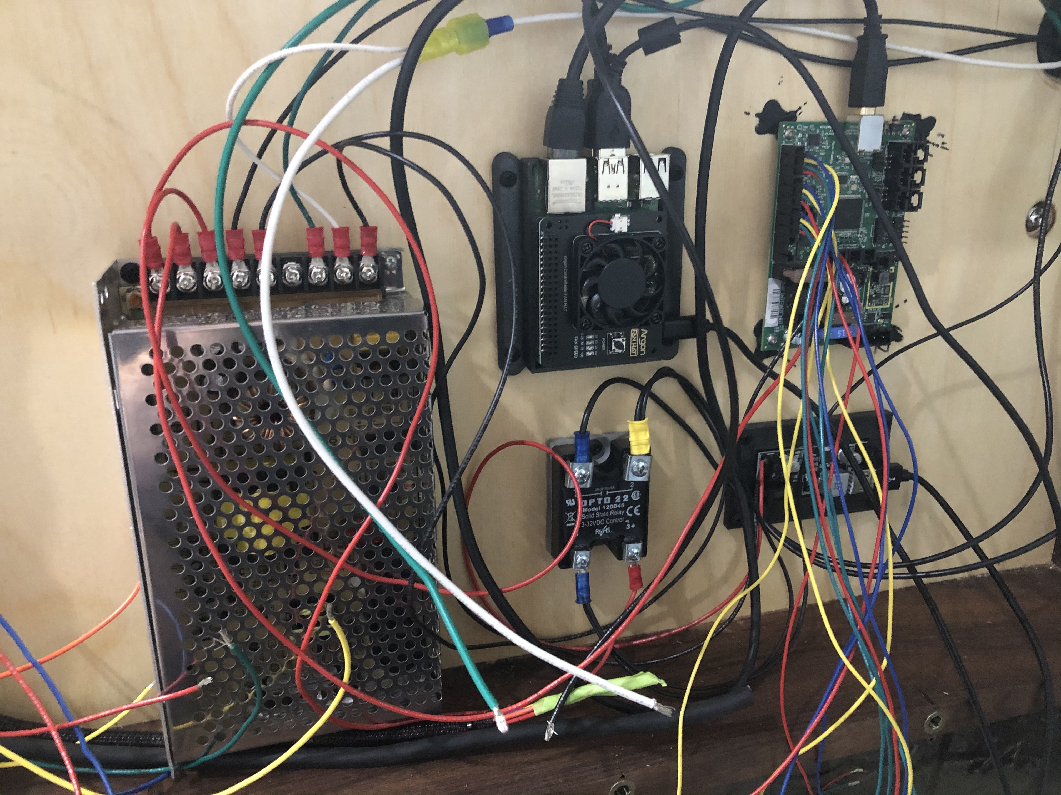
Lastly, my electronics cabinet and switches. I’ll include the principles I used and a wiring diagram but the actual construction and particulars of this part is really dependent on your table.
I did have to replace my original power supply at one point as the one that came with my mpcnc kit stopped working. I’ll include links to all the boards I went with including the buck converter to power the raspberry pie off the 12v power supply that handles the rest of the CNC. you may also notice I am running the mini Rambo board which has worked well for me. I have never required or missed the end stops.
I’ll add some pictures of the control box later this week after I get a few odds and ends in and clean up the wiring.
My only negative comment would be that it’s not a good idea to anchor anything to the top of the Z tower. Anything connected there has a very large mechanical advantage on the Z axis to produce tilt and affect perpendicularity of the tower. Even the resistance offered by a good drag chain has a potential with such a large mechanical advantage.
It is worth noting that the drag chain mounts I designed will reduce your useable cut area. This was a non-issue for me because it didn’t reduce the area any more than the vacuum attachment I also printed. The router mount and vacuum attachment is not my design although I did remix the vacuum attachment so it can be secured with screws and threaded inserts.
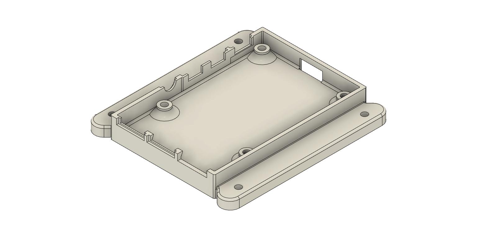
Buck Converter case, this is a very simple design, there are no mount points on the buck converter I posted so I simply epoxied the board into this case and then was able to screw it into the electrical enclosure.
PowerCon power connector, if you have never used a PowerCon connector you should try it, they are awesome.
EtherCon chassis connector I had never used this before I’m not sure it was worth the hassle as it ended up being pretty fiddly. I like it now that it is complete though.
Yes, I forgot I had done that. I thought it worked better for mounting the drag chain bracket. As I was messing with different bracket options it was much easier to flip the trucks and balance the bracket over the top of the stepper motor than to have the bracket on the other side flapping in the wind.
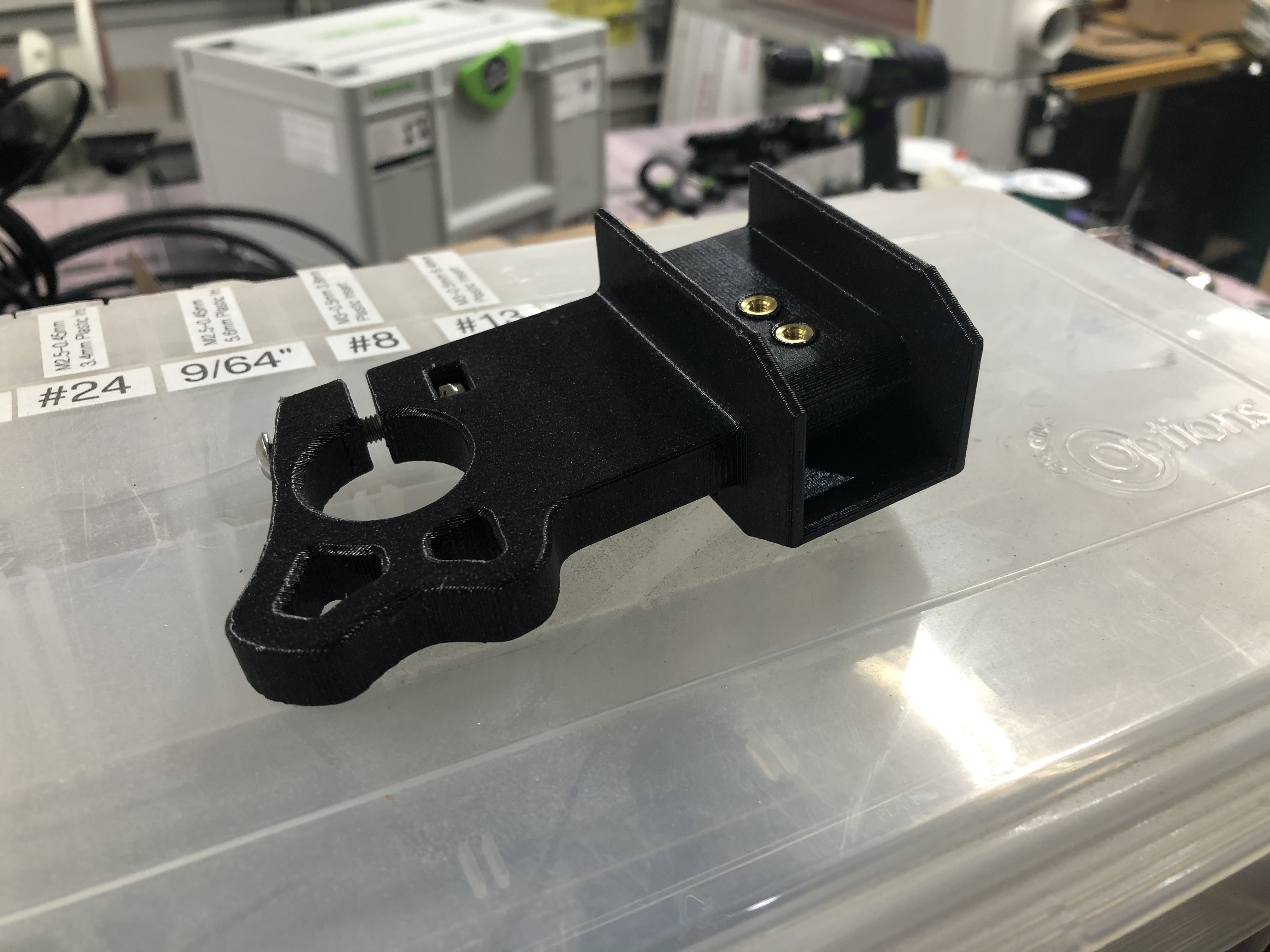
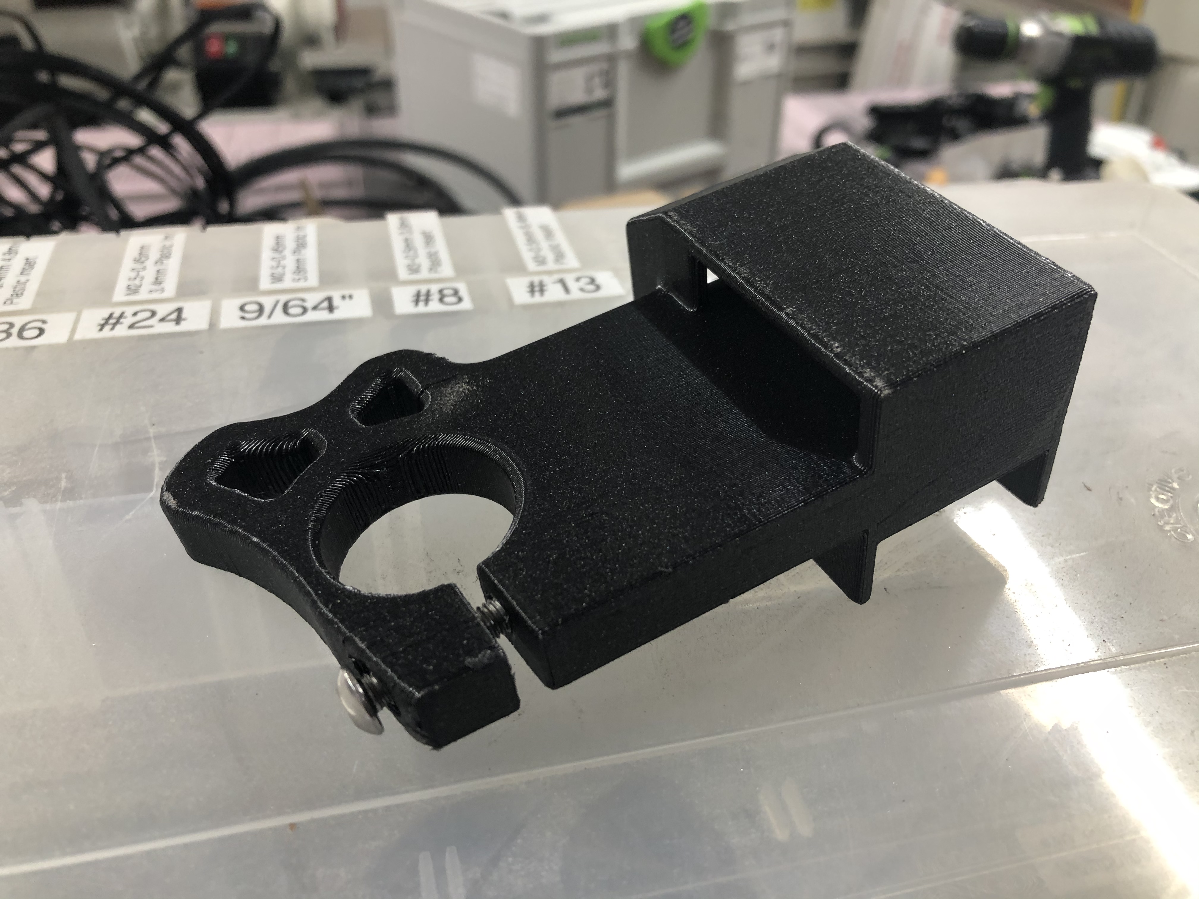
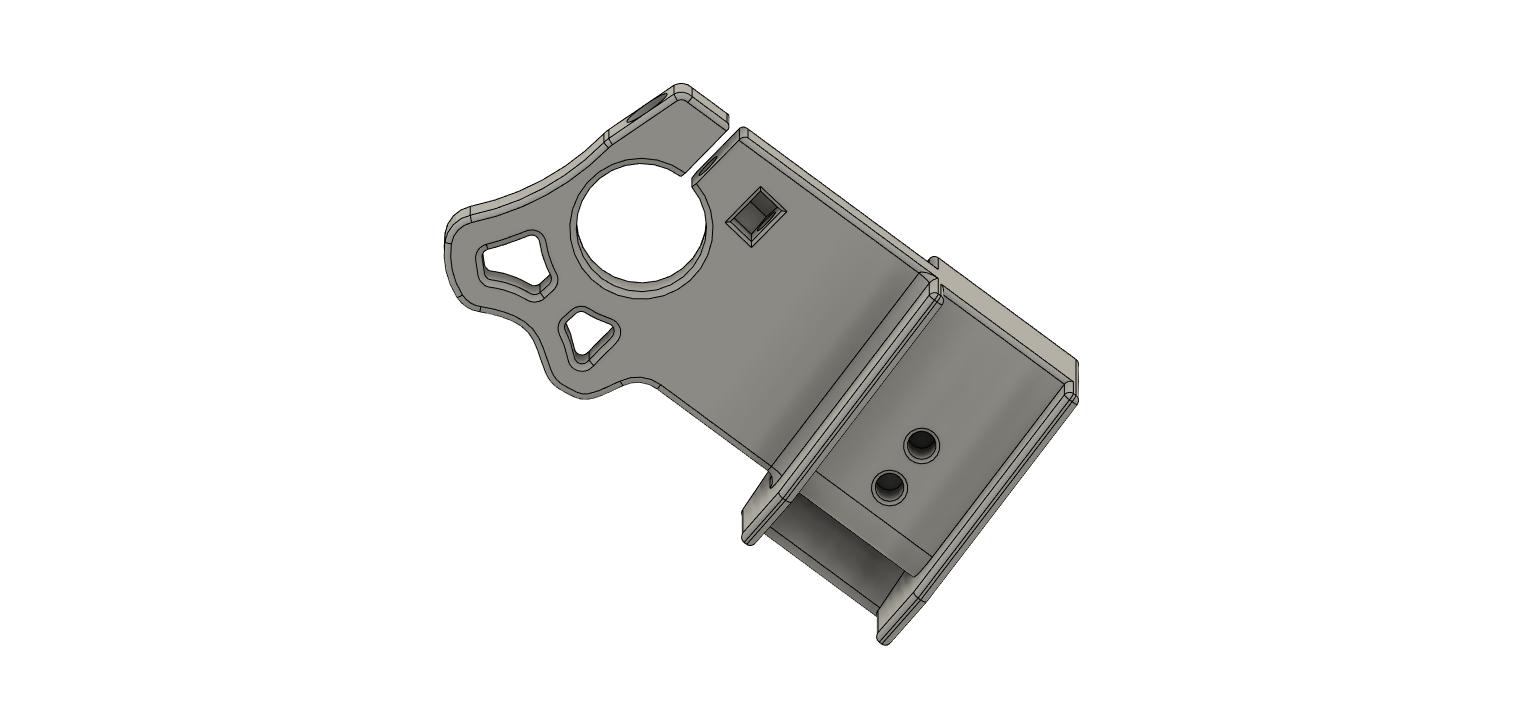
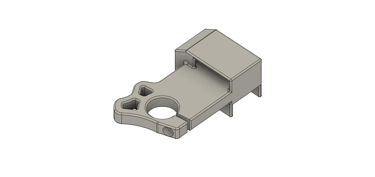
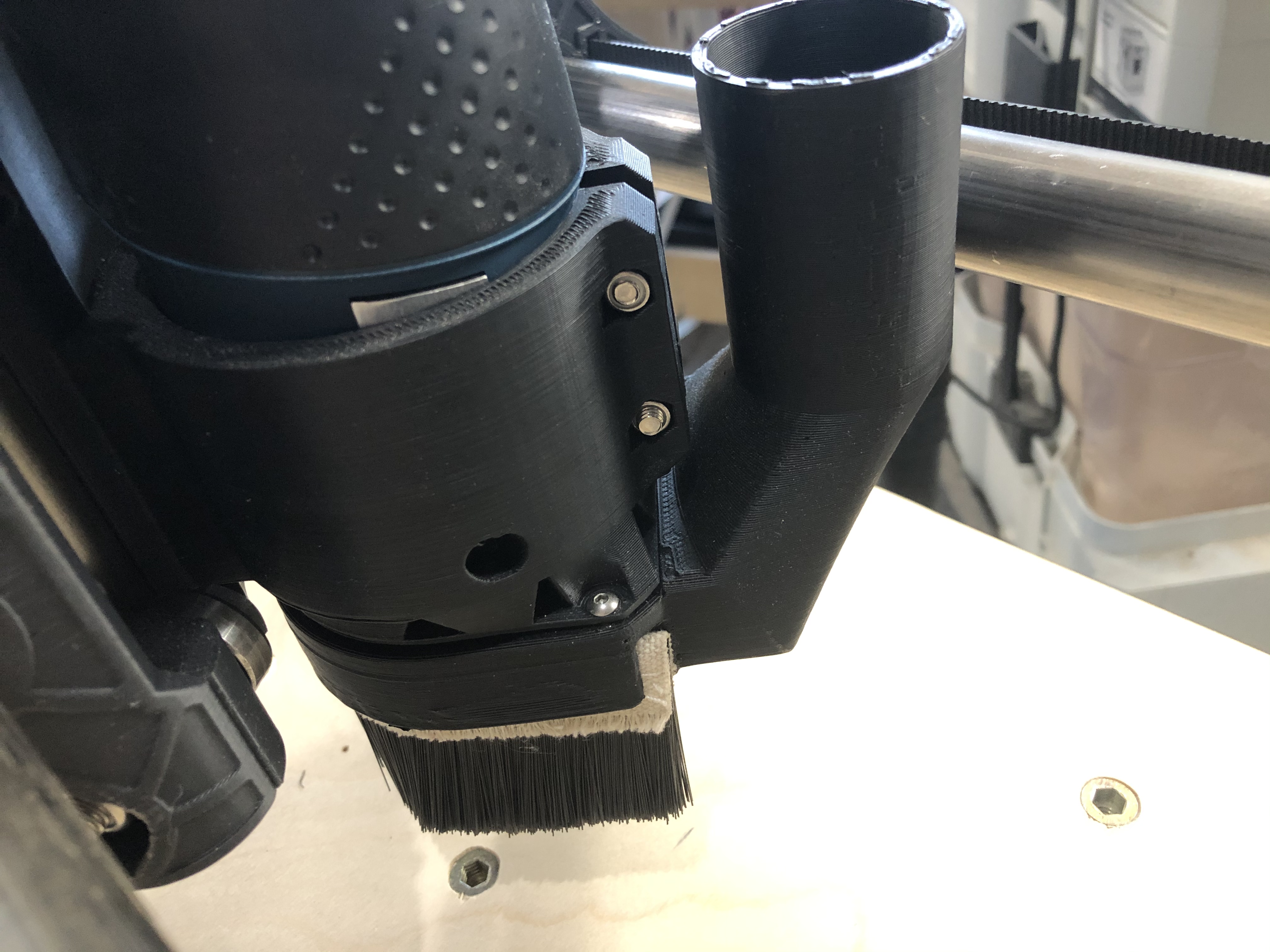
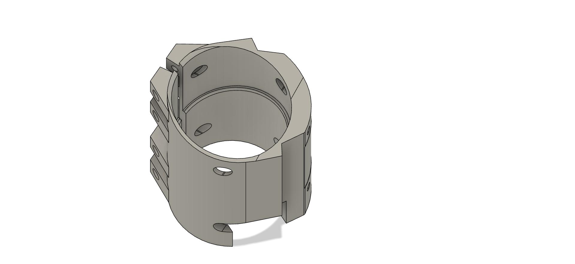
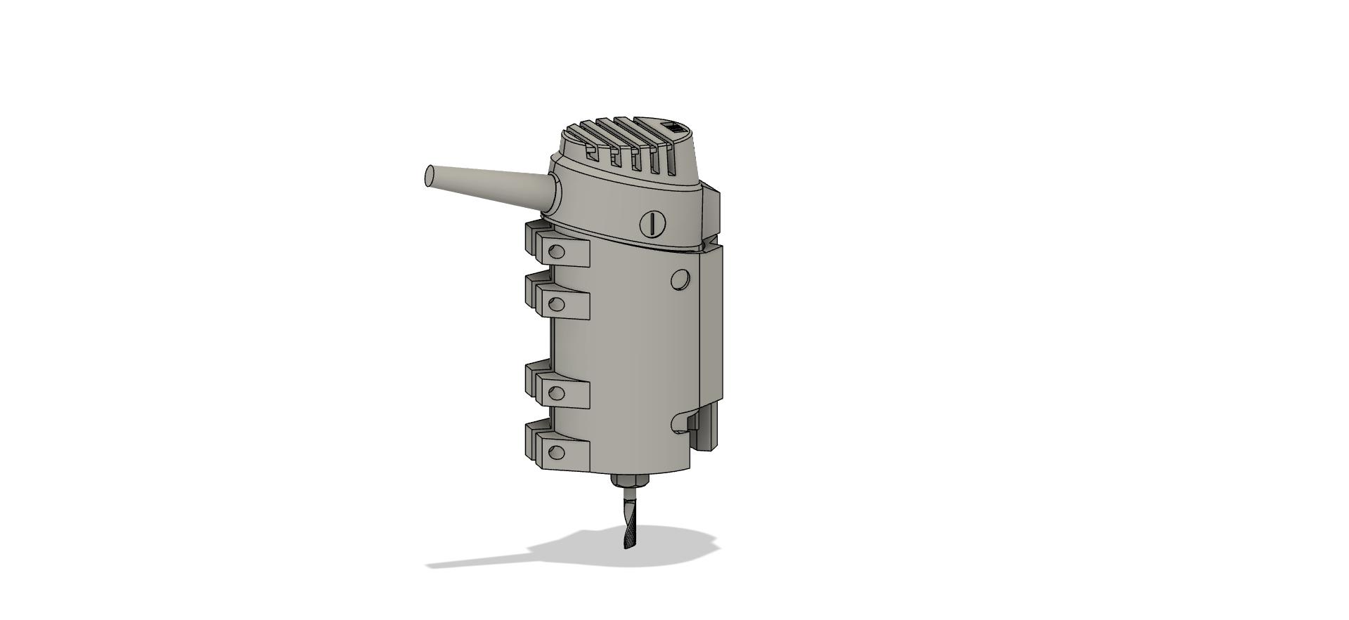
Something else I have been working on is a new mount for the Bosch Colt router that I use. I wasn’t happy with the one I got from Thingiverse just because it doesn’t seem very sturdy. Also, access to the spindle lock to change bits is not good. Rather than reworking it, I designed one from the ground up. It is a 20 hour print so it should be done sometime this evening. I embedded four neodymium magnets into the base and will make a custom vacuum attachment for it as well.
I cleaned up my electrical cabinet, I rand out of spade connectors though so I have some on the way and I will be able to finish this up. I am also working on creating a schematic for how everything is wired but I haven’t gotten to that yet. I may just go pen and paper with that for simplicity.
I have been prototyping the router mount now for the last week and I think I have settled on the final design. I am 24 hours into the 30 hour print that is the router mount and then I will start printing the vacuum attachment tomorrow. There are 5 10mm x 3mm neodymium magnets printed into the bottom of the bracket and 5 corresponding magnets embedded into the vacuum attachment. I have some spindle brush material that will slide into the channel. Hopefully it works!