Connecting Laser 3 wire driver ??

It’s as bad as I was expecting. Just received a Laser diode from Amazon, and as almost expecting without any documentation.
As I understood many people connect those lasers on the D9 port, but if I’m not mistaken, it can only switch the Laser on/off but the PWM is not working correctly, or at all. I have to measure anyhow first what the voltage output would be as I use a 19V Laptop PS in the moment, but have a 12V in stock.
I think others use the D44 pin for the PWM output, I guess another tinkering week ahead of me.

https://www.amazon.de/gp/product/B07T5C8M93/ref=ppx_yo_dt_b_asin_title_o01_s00?ie=UTF8&psc=1

1 Like

You have to find out what voltage your laser is expecting for it’s signal…if it uses that. The laser page should steer you to what you need to know. Finding another user with your exact same laser helps as well.

1 Like

Thanks Ryan, well at least it has a switch to turn the PWM off, so it could operate simply as cutter (maybe). Try to figure out that Pin 44 remapping thing. I read about here yesterday.

I’ll reluctantly jump in here to see if I can help… hopefully, not overwhelm/confuse. I’ve successfully hooked up a number of cheap import lasers to my various machines and been able to get virtually all of them running. NO GUARANTEES… but this is what I’ve found with the lasers I have experience with.

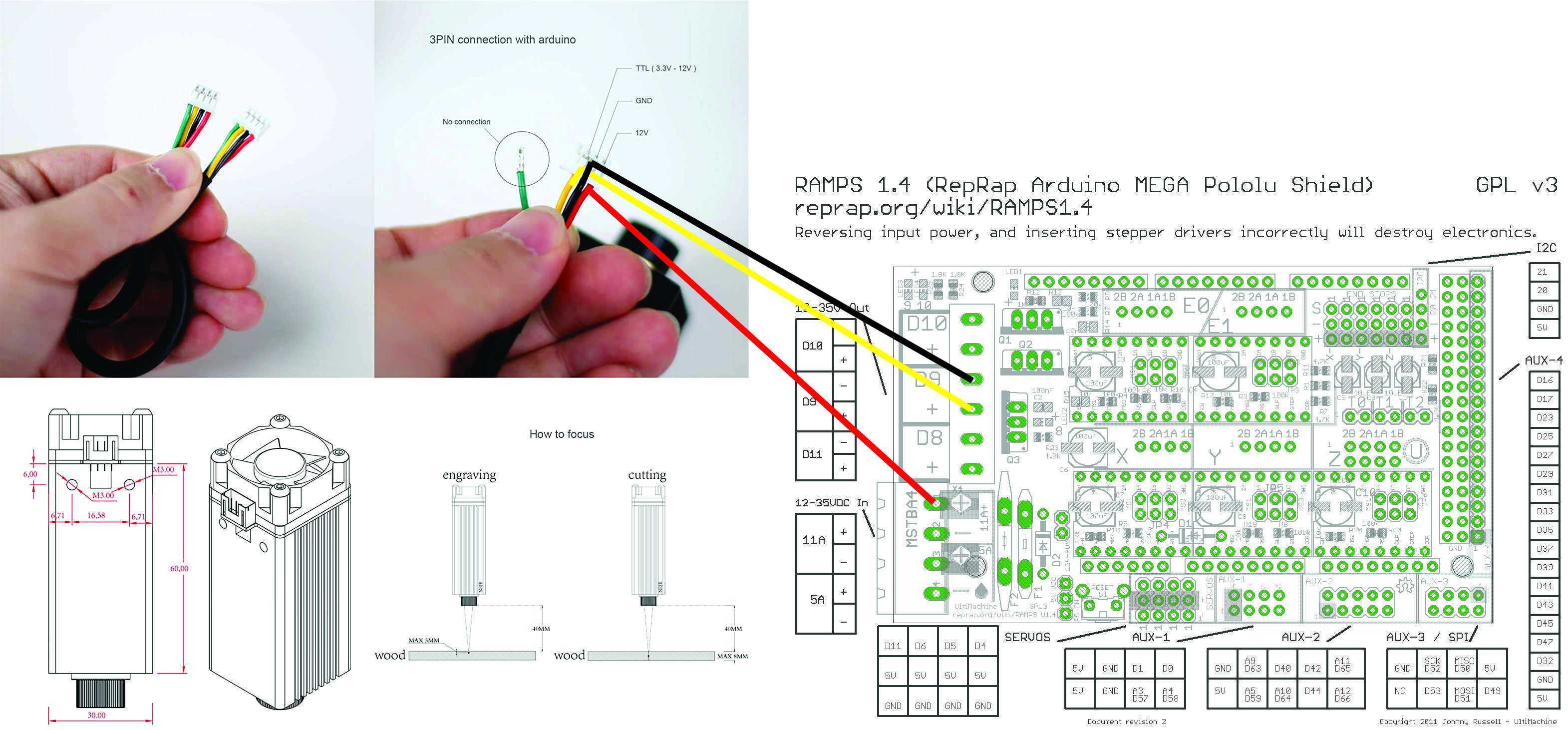
Most diode lasers (like most of the ones asked about on this forum) come in flavors… 2-wire, 3-wire, and 4-wire. Two of the wires are most certainly for power… any others are usually associated with intensity control (PWM). The voltage levels are commonly +12 volts for power… and either +12v or +5v for the PWM (this is where most of the confusion seems to be… when vendor info doesn’t specify the level). PWM (pulse-width modulation) speaks to the switching ON/OFF of a voltage level (commonly +12v or +5v)… with the duty-cycle (ratio of ON time to total period) controlling the average voltage… and thus the intensity of the laser output.

2-wire lasers (an L-Cheapo 2.1 watt laser a friend had falls into the category) usually are +12v lasers. Hooked to a constant +12v DC, they come on at full power… with no intensity control. Hooked to a +12v PWM signal, like the D9 fan signal from RAMPS and MKS Gen L, you can vary the intensity with the M106/M107 fan speed gcodes. L-Cheapo worked fine simply connected to the D9 fan screw terminals on a RAMPS board… be sure to observe polarity. That’s about all I can say about the 2-wire lasers I’ve seen.

4-wire lasers (my Banggood 3.5 watt lasers have had this) usually have two 2-pin connectors… one for +12v power and one for PWM. One wire in each connector is a GND wire. The power connector wires are simply hooked to the same +12v DC power as the controller board you are using. I also found somewhere in the provided info that the PWM levels for this laser is +5v only. M106/M107 gcodes are convenient and commonly used for controlling the part cooling fan (and lasers!) but this is a 12v PWM signal and can’t safely be hooked directly to the laser’s +5v PWM… so this is when pin “remapping” is used. Changing the D9 fan pin assignment (in “pins.h” IIRC) from “9” to “44” (RAMPS and MKS Gen L) allows the same M106/M107 gcodes to now control pin 44, which is a +5v signal… same PWM, different levels. And this can now be safely connected to laser’s PWM connector… pin 44 to the + and the - connects to a convenient GND.

3-wire lasers (the Eleksmaker 2.5 watt lasers I have) have a single 3-pin connector… if labelled, usually +. -, and PWM. The PWM levels are also +5v. These lasers are virtually the same hookup as the 4-wire lasers above… but share a single GND wire. So +12v power connects to laser’s + and - as usual… and pin 44 connects to the PWM pin.

In the photo below, note the red and black power wires hooked to the controller board (here, a MKS Gen L)… on the lower left side. Note also a couple of isolated wires, white and gray (straight across the board from the power connector)… these are the PWM control pins; i.e. white is pin 44 (remapped D9 fan pin) and gray is GND. These are all the wires needed to control your laser. The red and black are +12v DC power and will connect to the 3-/4-wire laser’s power connector (red to + and black to -) and the white “pin44” and gray “GND” wires will connect to the 4-wire laser’s PWM connector (white “pin44” to + and gray to -)… or, in the 3-wire case, the white “pin44” simply connects to the PWM pin in the laser’s 3-wire connector.

[attachment file=107841]

I’ve never used any of the more expensive lasers – JTech, Endurance, etc. – but it appears that, among other things, they have taken some pains to make a more robust/flexible PWM input. I suspect that the connections I described above would work fine for the ones that specify a range of PWM levels extending down to +5v or less. Pin remapping might not be necessary if you can find a suitable, already-existing PWM (D9 fan output?) signal… but I doubt it’ll hurt anything; i.e. hooking a +5v PWM signal to +12v-only PWM laser input might not modulate it properly but, at least, it should not blow it up, either.

The only other thing here, different controller boards won’t have a “pin 44”… but there will be a suitable pin somewhere that you can remap the part-cooling fan output to… and still allow for M106/M107 gcode control. On my miniRambo, that was the Z-min (pin 10) endstop pin IIRC.

I hope this helps someone. These laser connection questions are asked so many times, hopefully a more general explanation will help you figure out what you’ve got.

– David


4 Likes

Thanks a lot David.

That helped already a lot.

This laser, the PWM can be switched on/off, so for today I went to the most simple solution and simply connected the ±12V directly to the D9 port.

At least a start, but I doubt a permanent solution.

I’m using 106 S175 (69% according RH, don’t like the idea to run those China toys on 100%) and 107 to switch off.

A second try with S225 (88%) and 900mm/min, looks a bit better, but I think it far behind of what a 7000mW laser should be able to do. It struggles to get through a simple sheet of paper.

I seems that it has much less power on the PWM P9 +12V than when I connect it straight to the +12V.

Please recognize that a +12v PWM signal isn’t a full 12 volts unless you specify full power… M106 S255. Check out post #87479 on this page to see why…

https://www.v1engineering.com/forum/topic/laser-engraving-not-really-getting-great-results/page/2/

For cutting materials, ABSOLUTE BEST FOCUS is crucial. Use Ryan’s LaserFocus “script” to get it right…

https://www.v1engineering.com/forum/topic/laser-focus-script/

I use this any/every time I change materials/thickness. It makes a BIG difference, being properly focused. Air-assist will be the other thing you’ll want, eventually. I’ve got my air-assist setup documented in my FoamRipper thread. Here are a couple of engravings on cereal box cardboard (chipboard) – my favorite cheap test material – with focus patterns below…

[attachment file=107890]

[attachment file=107891]

My little 2.5 watt lasers are as good, or better, at cutting materials (up to 5mm luan plywood) than my 3.5 watt Banggood lasers. The spot size is smaller… and 2.5 watts concentrated in a smaller area can easily be “more powerful” than 3.5 watts spread over a larger area. It still takes multiple passes to cut thicker materials with these small lasers but is doable, if you’re patient, with BEST FOCUS and STRONG AIR-ASSIST.

– David


1 Like

Thanks again, I went through the threads before, well not into too much detail.

Overnight, I had a brilliant idea, well, that’s what I thought.

I put the laser back on it’s 12V from the power supply, measured the D9 pin.

+5V are reached @40 in RH, aka M106 S102, so I wired D9 to the PWM/TTL pin on the laser, and absolutely nothing is happening. If I use the switch on the driver board (PWM on/off) it fires.

Doesn’t matter if I do it manually with the fan control in RH, or running Ryans script, (with M106 S102, instead of M106 S255). I double checked, that the +5V really get to the driver board.

I’ll playing around a bit with the simple on/off mode, but after that I’ll send it back. Not worth the money.

CAUTION: Please recognize that if the PWM input to your laser is a +5v input (if it’s really TTL as claimed, it is!)…putting the D9 fan signal directly – AT ANY POWER SETTING – is still putting a +12v signal on that input. Hopefully it’s protected… otherwise it may be blown. And this is probably why it didn’t work.

If you “measured” the D9 voltage with anything other than a scope … you were almost certainly reading the AVERAGE voltage; i.e. 40% of +12 volts. PLEASE check and RE-READ CAREFULLY that first link in my last post.

D9 is a signal that switches between 0v and +12v ALWAYS for any power setting (other than zero)… only the DUTY CYCLE changes; i.e. the signal is +12v 40% of the time for M106 S102… 0v for the rest of the period.

You will need to REMAP the D9 fan output to a +5v PWM-capable pin for your controller board to use PWM with this laser. What controller board are you using?

For now, I would try once again to use the 2-wire connection scheme… connect the D9 fan signal to the POWER pins on your laser. Observe the polarity! You can probably ignore the PWM input and leave it unconnected… you may need to try turning it ON/OFF with that switch.

If the PWM input withstood the abuse (i.e. it was protected) it may be alright. But please don’t try using it that way (PWM) again… until you know more about remapping the D9 signal for your controller board.

And PLEASE DON’T GIVE UP on this. It will be very rewarding to you if you can hang in there and get this running. But it is NOT TRIVIAL… and, given the limited information you have, you really need to READ CAREFULLY all the information that is being given.

– David


Thanks,

The good news, it’s not fried…(yet) ;-D

I did not yet remap Pin 44, simply used M42 P44 Sxxx to test.

After that success I guess I go for a early beer today.

Makes now much more sense too, as soon it’s on +12V the driver and laser fan are on permanently it fires as soon M42 P44 Sxxx is higher than 0.


Good to hear that it seems okay. If you are using pin 44… you are using a RAMPS? MKS Gen L?

I didn’t know about the M42 trick… read up on it and that sure seems a good way to check whether or not it works… before doing the firmware edits and compile/upload.

Very good!

– David

The remapping from D9 to D44 was easy, much easier than I expected. Just one small change in “pins_RAMPS.h”

I’m using the MKS Gen 1.4. There is a file for pins_MKS_13, but within the file “pins_RAMPS.h” is loaded.

Made a few small scripts to test the cutting ability, and it’s far from good. Running Ryans script to adjust the focus. Then still it need 40 passes to get through 3.6mm multiplex, going down 0.1mm every pass, there I was expecting much more.

6mm cardboard looks better, 4-5 passes, adjusting the Z by -0.8mm gets me through.

It seems to me that there are actually 3 small dots instead of one, but that might just be because of the protection glasses. On the testing script it draws a fine line if in position.

I made 2 tests with the ImageToGcode. The functionality is given, but the results are very blurry, have to go through all the threads, probably bad settings from my part.

Conclusion:

Lasers are fun, but the flimsy focus adjustment on this particular one, is not worth the almost 190$. For that money you’ll get a CO2 40W tube and a set of mirrors too. So, most probably this one goes back, and I go for another cheapo from China, guess I can almost do the same with a good 2.5 - 3.5W, which cost a fraction.

So yesterday I was reading through the whole https://www.v1engineering.com/forum/topic/laser-engraving-not-really-getting-great-results/page/6/ applied the changes in Marlin.cpp and I was good to go.

First picture is a simple bitmap which I aborted yesterday and then did again today with much better results after the change.

Then I went to Davids G-code file, for the Garfield, that file is firing the laser up to 100%, so was not really working for me -LoL. Results on the right :smiley:

I used then the jpeg image and did my own G-code file. 40% 50mm/s resolution in width 0.15mm, height 0.17mm. I could notice the X-axis slowing down, but overall not a bad result for one of the first trials.

Thanks again everybody for their help.

1 Like

Hi Sir,

Joined the group as your post sticks out to me as I just purchased a SainSmart 5.5w laser to use. I have two 3d printers, one of which I have upgraded along the way. I now have an MKS Gen L V1.0 board and screen laying around and would like to utilize this. I will have to get a new PSU for this dedicated build, but at least I can get a 12v PSU in place of the dedicated 24v PSU I use for the printers…

From what I read on your post, looks as if I can simply change the PIN configuration in pins.h within Marlin to address the 5v pwm essentially? FYI, totally new to all of this, like I impulse bought this laser to use for some leather engraving and scoring to make accurate cuts…Not sure if you’re using grbl?

I still have a lot of reading to do to wrap my head around all of this. So, if I am totally off base, let me know, and I will keep digging!

Thanks,
Aron

1 Like

Hi, looking at getting NEJE 7W Engraving Module,2.5W Output. connecting to Ramps 1.4/Mega 2560. information on connections confusing, PWM/TTL Input:DC3.3V-12V . attaching pic for power & control, might this work?

Thanks
Clay

I just ordered the full-size rambo board and I noticed mention of laser support being enabled in the firmware… can someone please elaborate on what that means? I have the la03-3500 laser from banggood and I had a standard ramps set-up before, with d9 remapped to pin 44, where would i plug it in on the rambo?

From the hardware side I recently helped someone else get their laser running. In the latest version of the firmware, pin 45 is defined as the laser and spindle speed control pin. You will find this line in pins_RAMBO.h:

#define SPINDLE_LASER_PWM_PIN                 45  // Hardware PWM

And you can find that pin here on the Rambo board in this pic:

Rambo1_4_ExtraPins

The laser is then controlled using the ‘s’ parameter of G1 commands with values in the range of 0 to 255.

Since you have a working setup, you probably already know this, but if you are powering your laser from a separate power supply, that supply and the control board must share a ground connection.

Thank you! That is immensely helpful.

CAUTION:

I know that this is an old post but I’m just putting this here for anyone that may run across it in future. I have one of the NEJE lasers as well however when mine arrived the wiring harness although the same as pictured above was originally opposite from the factory!
In other words, from the factory, Green was 12V, Yellow was Ground, Black was PWM and Red was C (Temp). I switched the wires so that the color coding makes sense.
If you don’t switch the wires on the laser plug. You would likely burn out your laser module if you hook it up as shown above.

3 Likes

I also received my Neje 20W laser with the supplied laser cable color coding bass-ackward (left-to-right vs right-to-left); i.e. against convention. I re-ordered the wires to use a more conventional red and black for +POWER and GND, respectively… yellow for PWM, and green for TEMPERATURE/C. While the wires don’t really care what color they are… it might well confuse you if you aren’t sure of what wire is carrying what… :astonished:

2 Likes

Hi @dkj4linux would you please tell me in your experience which diode laser I could attach to my MPCNC using MKS board and able to cut 5mm acrylic? Thanks