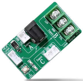
I have converted my original Burley MPCNC to a laser engraver using one of the Neje lasers. It’s running GRBL1.1 on an MKS DLC32 controller. Until now, I’ve used two separate power supplies so one of them feeds the MKS DLC32 and the other supplies the 12VDC to the Neje “adapter board” through the jack on what is referred to as “Input A”. The PWM comes from the DLC32 and connects to the Neje adapter board using the 2 wire connection, also at “Input A”. (See the image below)
This setup seems to work fine and correctly operates X, Y, Z and the laser.
However, I’m wanting to modify this setup with an exhausted enclosure, possibly a bigger laser etc. and so, to simplify things I acquired a larger, 12VDC 20A power supply with 3 outputs so that I may be able to operate the entire setup from this unit. (I also have VOC, CO2 and particulate monitors running on microcontrollers for monitoring the emissions from this setup, so a little extra power would be useful.)
But, the initial effort to do this has failed. When I replaced the DLC32 and laser 12VDC connections with two outputs from the new power supply, the laser is not responsive to the PWM signal. In fact, the PWM signal itself seems to be screwed up… Instead of the expected (and measured) 1 KHz square wave as measured at the adapter board, there does not seem to actually be any PWM signal. Instead, the laser comes on at full power and remains at full power, being completely non-responsive.
In fact, all it takes for this behavior to occur is for only the ground connection from the second input to be connected–the 12VDC can be omitted and the same behavior i observed.
I have a vague sense that I have seen some discussion about problems like this occurring using the same power source, but I’ve not been able to find anything definitive. It might have referred to needing some addition of a resistor someplace or ???
Because this may seem confusing to some, here are some images of what I’m seeing.
Neje adapter board. Normal connections made in “Input A” section. Scope monitor between GND and TTL in the “Input B” section. For the “laser pwm” measurements, the scope is connected between GND and the signal on the 4 pin laser connector.
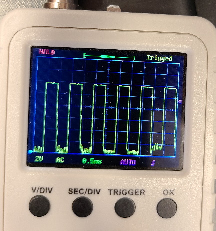
Next is the measured PWM when things are working corrrectly.
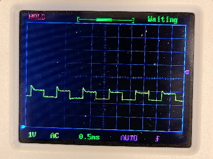
At the laser output, the signal can also be measured, although I don’t fully understand what is occuring:
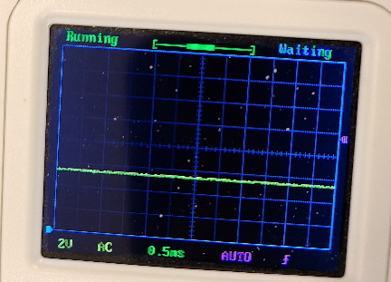
However, when the laser and controller come from the same power supply, here is the PWM signal… yes, there is no PWM signal that is apparent. The scope trace does not change when the controller sends the signal. But, the laser is on at full power.
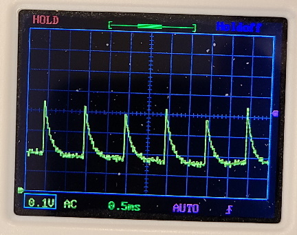
And, at the laser output, there is some indication of the “spiky” part of the PWM, but no square wave.
Finally, for fun, here is a link to a short video of the signal at the laser output as it turns on. I don’t think this adds anything except to note the transient behavior.