I’ve been working on a case design that will hold my 30 amp power supply, and that can be easily customized if I change displays or controller boards. I also wanted to be able to easily replace the rear panel so I can have cut outs for different connectors as I add or remove them. Originally I had really big parts that you could only print on an MPCNC or other large format printer, but I decided to give myself a challenge and redesign it so it can be printed on a 3D printer that has a 6"x6" capacity. The frame will… hopefully… snap together. The panels will be held on with screws. I have to go look for screws and see how available tapered screws are. I may make tapered screws an option. There are two internal beams that have screw holes every half an inch, so mounting plates can be made to attach to it. I haven’t decided which way I want the orientation of my Rambo board to be yet, so I haven’t made it yet. I still need to decide how I am securing the power supply too. Not sure if I want to screw up through the bottom panels, or attach to the internal beams that control boards sit on. I’m leaning towards attaching to the beams.
I am doing all of this in OpenSCAD, so there are some options. The panel thickness can be changed, and you can set a flag whether or not to make the panels large to be but on a CNC, or if they need to be small to 3D print. I do everything in inches, but use scaling functions, so if you change inches_to_mm from 25.4 to just 25, you get a nice even metric version too (though, the power supply would just barely fit then). You can actually just set it to any higher value too and it will generate a bigger box.
I haven’t printed this yet. So far it’s just a concept, but I wanted to share it, and see if anyone who has more experience than me can see some short comings, and suggestions for what might need to be changed.
When it comes to screws, I’ve always just used M3 or M4 bolts. 3d print the hole for them slightly smaller than the thread width. The first time you screw in the bolt, it will cut it’s own threads into the plastic. I’ve never had a need to use screws in PLA or ABS with this method.
I didn’t plan on putting nuts on them. I did make the holes smaller, and planned on getting some self tapping screws that are meant for plastic. I’ll print some small pieces out and test what sizes work best.
Well, I was trying to cut the panels on my mpcnc, but decided I had some practice that needed to be done before hand, so I put the panels on my table saw. I have to drill out the corners still, and make the screen and back panels. Originally I was going to repaint it, but I kind of like the beat up look so far.
I like it. Aluminum panels on a 3d printed framework, yes?
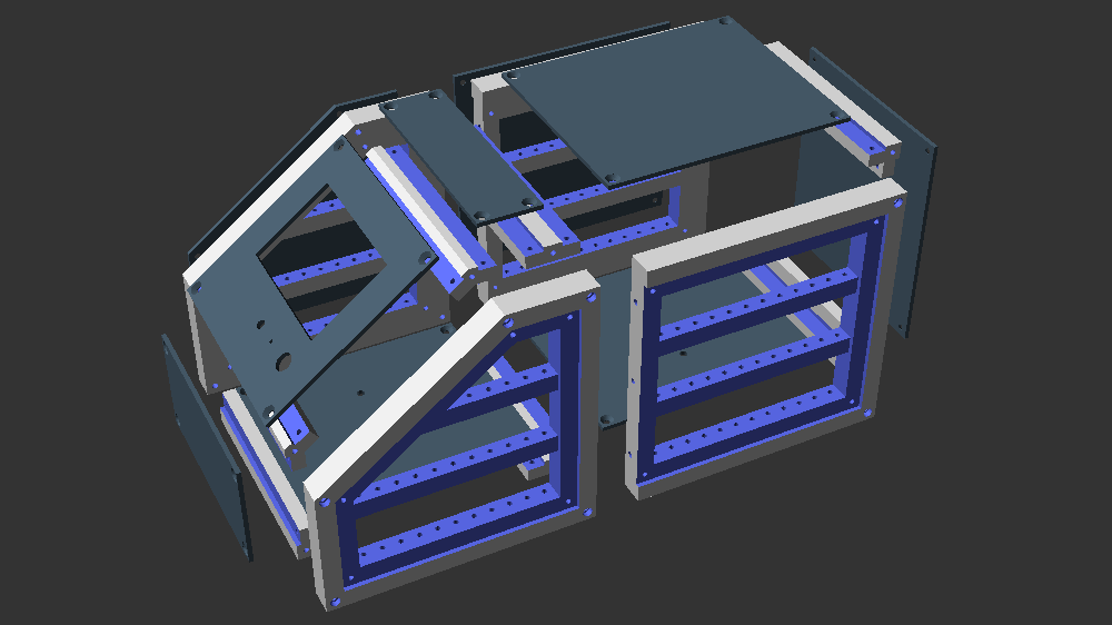
When you say “snap together” is that a friction fit? or something more elaborate? Based on the renders it looks like a dowel in hole sort of arrangement, but it’s not real clear to me.
The frame is friction fit. The panels will screw on, and help hold it together. The red “pegs” you see in the rendering were to help me see the connection points. At each of those points, one piece is a peg, and the other has a hole for it to press into. I’m not real happy with the say they go together, but it was what worked the best when I was making small pieces as tests. The OpenSCAD code is available on github if anyone wants to help make it better.
This project has been on the back burner for a while. My MPCNC has been packed up for the most part even. I finally got back to playing around with this, because I need it for my MPCNC and I want to use it for a modded 3D printer I have. Today was the first time I tried to mount anything in the case. I was glad the power supply fit, but there are some small issues I may need to fix if I intend for others to be able to use it. The are screws that hold the bottom panel on, and they get in the way of the power supply being put in. Also, the back bracket has to be removed to slide the power supply in and out, so it wouldn’t be able to be glued on or you would have to break the case to replace a power supply if it goes bad.
Also, I am a sucker for nice round dimensions, and designed this to be 6"x6"x12". I have done much more cad stuff since I initially did it, and I feel I might be better off making it a rounded metric dimension instead. The OpenSCAD files let you set a value for how many mm per inch, and if you change it to 25 instead of 25.4, it will make a nice even metric version, but it’s a bit tight for my power supply. Not sure now if I want to stick with these dimensions or make it slightly bigger and do things based off metric sizes.
I have to reprint the inside support beams to make the holes smaller for screws. I also had a small “ah ha” moment today. I plan to use this case design for a heavily modded 3D printer I have as well, and I want to fit a raspberry pi and a power relay and some other stuff in it as well, but don’t want it too cramped to block air flow. If I just print a few extra existing pieces, I shoud be able to just extend the case and make it longer without any additional design tweaks.
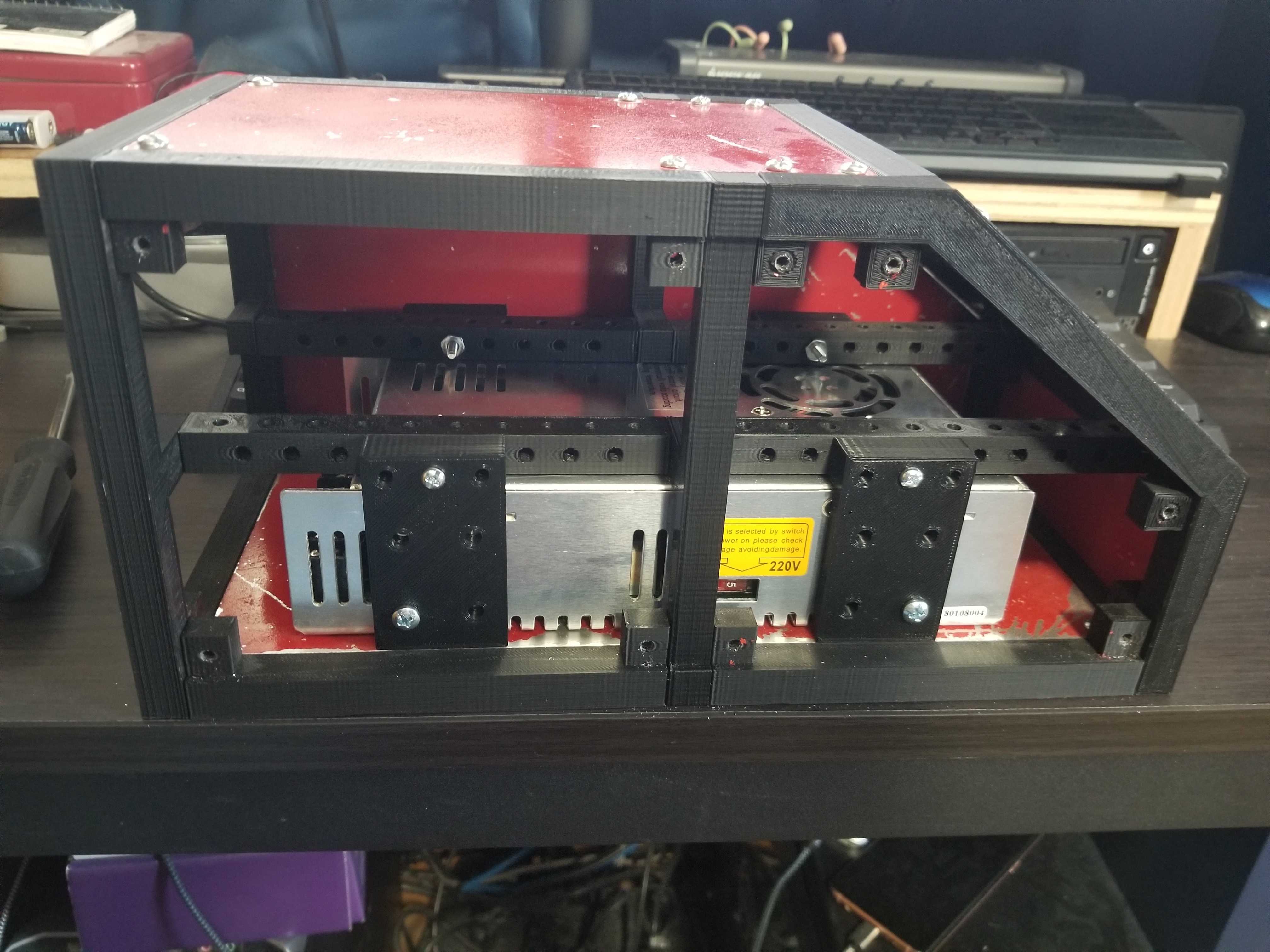
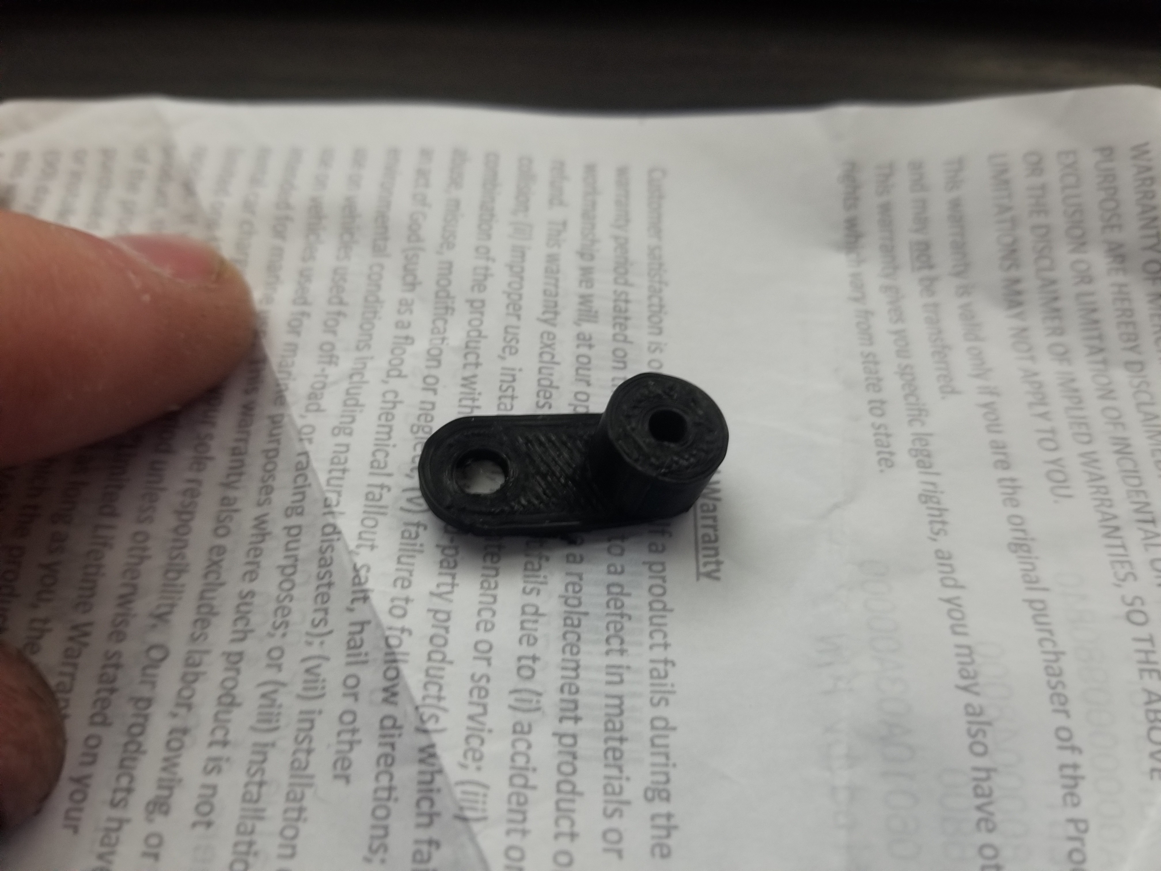
I had a few issues with my measurements. I thought I had each of the holes on the internal mounting bars spaced in 1/2 inch increments, but because in order to make the beams all be the same length, the gap from hole to hole accross the middle bracket is 1 1/4" instead. I am probably going to change that in the design so that any mount made for the case can be placed anywhere on the board. For my Rambo, I was going to make a full mount plate, but when I thought about it, all I needed was these little adapter studs.
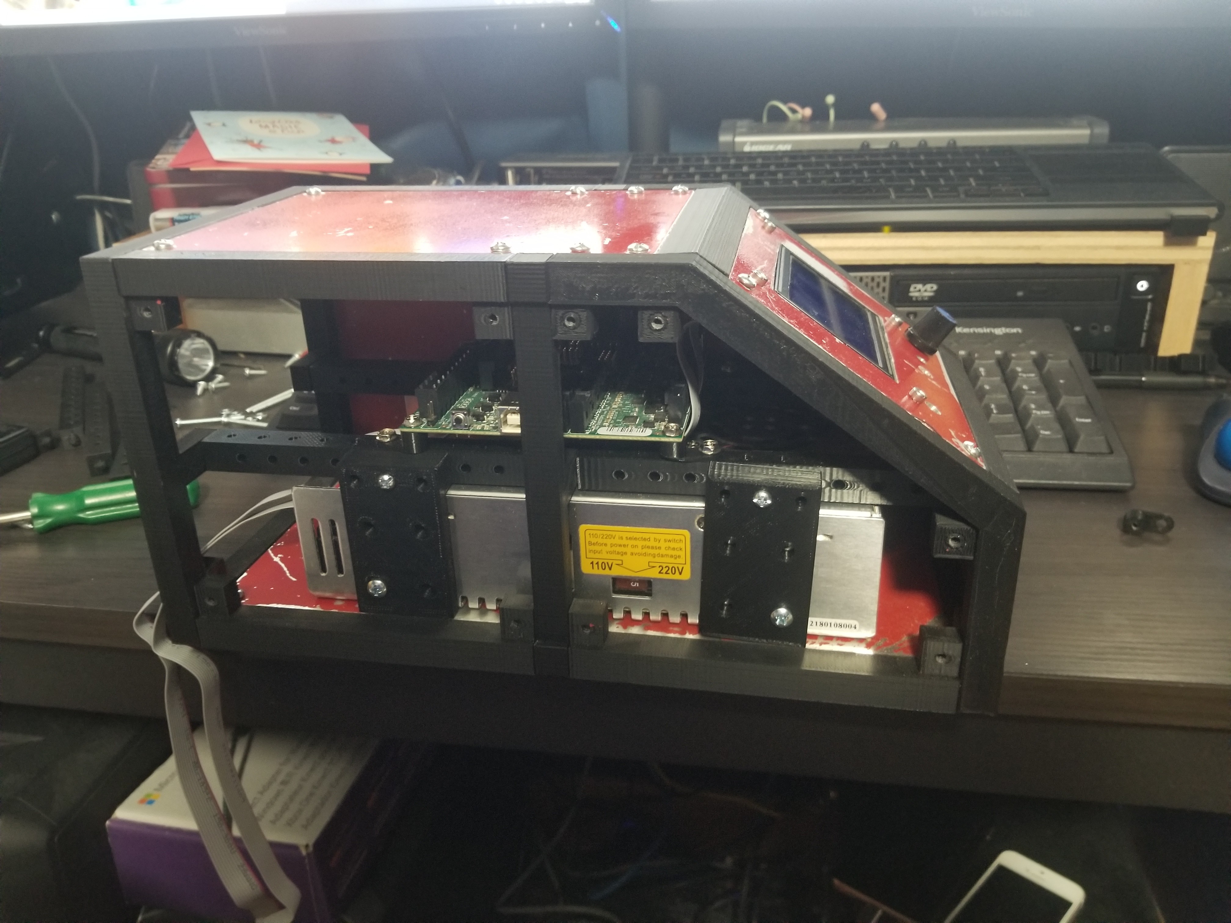
I still might flip the rambo board around to make wiring easier, and I need to get some fan vents in the front, but here it is with the board mounted in it. Oh, need to decide how I want to do the back panel still.
I seem to only get to work on this for short bursts at a time. As I got the other case assembled, I started finding things that I didn’t like. The case was all press together, and the panels would hold it if you were using large panels. If you were using smaller 3d printed panels, nothing would be holding it unless you glued it. Even with large panels though, nothing was helping to hold the rear frame in place, and you can’t glue it because you need to pull it off if you want to put the power supply or pull it out. I also decided there was too much wasted space above the board. Oh, and the more I do CAD, the more hassle it is to stick with freedome units, so I have ditched that in favor of metric completely.
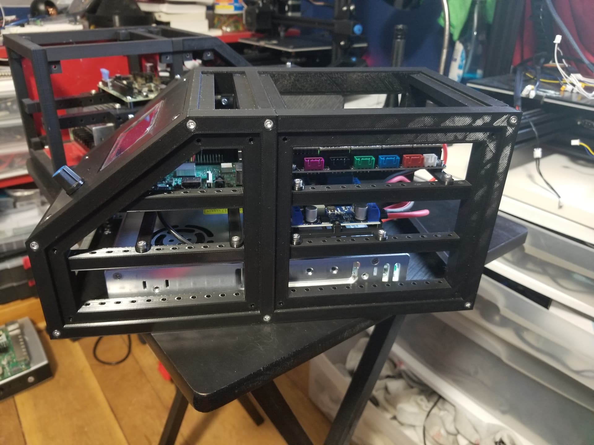
So, version 2 of my case has the board support rails built into the side frame. I was worried it would be hard to get screws in, but they go in easily enough with a ball head hex wrench. Rather than snapping the frame together, I have the front and back half joined with screws, as well as the cross braces. Not sure why I didn’t think of that before. Originally I wanted the pieces to be as small as possible too, since I was new to printing, and was worried my prints would fail. It’s not really an issue now, so I went ahead and made the frame pieces larger. Overall, I am happy with the new design so far. I am just debating if I want fans in the front or back now, and how I want to get wires through the back panel. I may just put a hole through it for the moment, but in the long run, I want some sort of wiring harness I can just plug into the back so I can easily unplug it if I need to move things, then plug it back in without thinking about it.
In the picture below, I have an MKS SGEN L v1 that is for a 3d printer I am working on, along with a raspberry pi, buck converter to power the pi, and a relay so the pi can turn the printer on and off. Don’t think I will put a pi in the case for my MPCNC, but there is definitely room for it.