As you describe your problem, my first thought is to use a servo rather than a stepper motor. A servo has absolute positioning, and Marlin g-code has a M280 to set the position. The only problem is that the PINS file for the MiniRambo does not have any servo pins defined. If there are any available pins on the MiniRambo, you should be able to use them for driving a servo.
As for driving a fourth stepper, the first hack that comes to mind is to have Marlin treat it like an extruder, and use G10 (Retract) and G11 (Recover) to set the angle. This is a completely untested idea, and will require you to enable an extruder in the firmware.
Edit: I did a bit more looking around. There is no free PWM pin on the MiniRambo for a servo, but one can be freed up from the endstop pins. See the " PWM Pin for a Servo (pin remapping)" on this webpage. I’d be reluctant to power the servo off the 5V rail on the MiniRambo, and would use a separate voltage regulator.
I looked a bit further on running the 4th stepper as a extruder. In addition to Retract/Recover, The G0 through G4 parameters have an E parameter that you may be able to to use to control this fourth stepper. If I were attempting to enable the extruder in the MPCNC firmware, I’d do a “diff” between the configuration.h and configuration_adv.h files of the MiniRambo MPCNC firmware and the same files in the MiniRambo version of the 3DP firmware (which has an extruder enabled). My current diff tool is Meld.
This is going to be tricky. My impression is that it is a little bit like the tangential cutter problem, where we were trying to move a 4th axis so the razor blade was always parallel with the path. This thread is long, and we go back and forth on how we should do it. But it may give you an idea of the magnitude of the problem, and maybe there are some working steps.
Here is how I would break this problem down:
Switch to the mp3dp firmware for the mini rambo. Get it at MarlinBuilder releases. V510, V13DP_MiniRambo. Open it in platformio and compile it, then flash it. This won’t change much, but you will have proven your tools work.
Disable the temperature checks (I think it is something called cold extrusion) or just change the thermistor to the 999 dummy and the dummy value to 175. With this flashed, you should be able to send commands like G1 E10 F300 and see the E motor turn. The steps/unit need to be changed to be steps per degree.
The hardest part is generating the gcode. I think the easiest way is probably to write a script (I know) that will take in the XYZ gcode and predict what values for E you would need. Then output a file with the E values set on each movement command. I remember talking a lot about that on the tangential cutter thread, but I don’t remember how far it got.
Two indepth responses, wow, and thanks. I have not had good luck with servos, so I’m going to pursue the hyjacking of the Extruder function. Between the two relies I beleive I have enough to get started.
But before i do, would it make more sense to swap my miniRambo for a full Rambo? Would that make it easier and give me more options in the future?
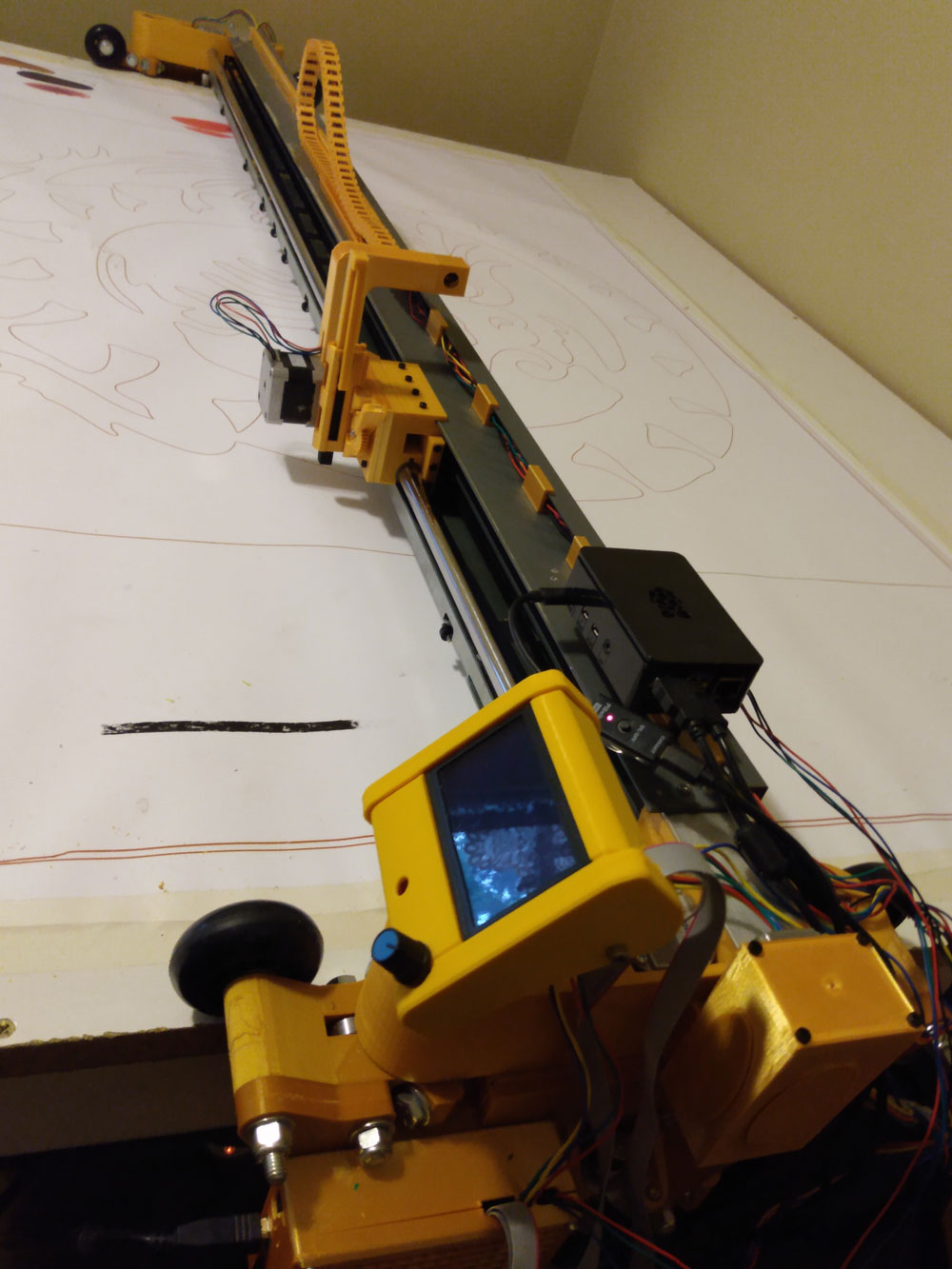
Also, I attached an image just to give some context. The x-arm is cannibalized from a plotter. -remo
The microprocessors are the same for the Rambo and MiniRambo, and for this tool, you don’t need extra pins, so I cannot think of a benefit for now. A full Rambo will give a number of free pins that you can use plus one additional stepper driver. I’m not sure of your drawing goals, nor what issues you are currently facing. A board with a 32-bit microprocessor (like the SKR Pro) might yield faster and/or smoother drawing. Cool use of an MPCNC.
I want to paint with the machine. The tool holds a square oil pastel stick, one of the ways artists apply paint to canvas. I have changed it since this photo…it now has a solenoid to press the oil stick firmly to the surface. My next step is to be able to activate the solenoid with a gcode.
I’m thinking I need a relay. I can use X end stop pins to activate the relay sending 12 volts to my solenoid. Do you think this will work?
Can I use the MiniRambo 12 volts or should it be a separate power source?
How much current does the solenoid take, and is it protected against back emf? (I don’t know much about solenoids, but opening the circuit may create a big spike of current, which can be fixed with a diode).
The fan pins are 12V and can support a lot of (a lot more than the
micro controller, at least) current. M106 to turn it on and M107 to turn it off.
Can I use the MiniRambo 12 volts or should it be a separate power source?
What you can or cannot do will depend on the specs of the solenoid. If you post a link to the solenoid your purchased, or better yet the datasheet, then forum members are going to be able to give you good advice on how the solenoid needs to be installed. It is possible, even likely, that you can drive it directly off the fan pins. The circuit provides for up to 5A for the heated bed, fans, and logic, and with no heated bed, you should have plenty of headroom to drive a solenoid. You may or may not have to upgrade your power supply for the MiniRambo.
As Jeff suggests, you can use the M106 and M107. Near as I can tell, there are only two fan ports on MiniRambo. They are labeled Fan1 and Fan2, so you may have to add a parameter to the g-code. Something like:
M106 P2  ; Turn on Fan2

M107 P2  ; Turn off Fan2
The first step will be to execute an M106 and checking the fan pins with a multimeter.
I’m curious about the solenoid. Other than moving faster, what doe sit provide that cannot be done just by moving the Z axis up and down?