Before you do trace bitmap in inkscape, make the picture black and white (not grayscale, true two color black and white). trace bitmap will work better with a 2 color photo.
Trying to make things that match real world object using photographs is painful…primarily due to perspective issues. When I can, I used a flatbed scanner instead of a camera. Here is how I would approach this problem (untested):
Lay a series of 8 1/2 x 11 sheets of paper edge to edge and tape them together into a single sheet at least as big as your foam. Add lines to indicate the edges of the foam.
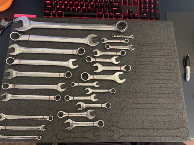
Layout and trace out all the wrenches on the paper. You want nice black lines.
Add some registration marks to the papers so they can be reassembled (I’d use several colors to make reassembly easier), then take a picture of the whole thing for reference.
Cut the papers apart and scan in all the papers using a flatbed scanner.
In Photoshop, reassemble all the pages using the registration marks. If there is any slight gray on the scans, it can usually be eliminated with a bit of Levels.
Flood fill then perhaps smooth the outlines for all the wrenches. Perhaps remove the registration marks.
Use trace bitmap in Inkscape to generate the .SVG file
It looks like a lot of steps, but if you have Photoshop (or other decent image editor) and a flatbed scanner, it would not take very long.
I’d be a bit surprised if PTGui would reassemble the images. Most image stitching software I’ve used (it has been a few years) required an overlap between images and a focal length of the lens in order to do the stitching. GIMP is free and will do the job. Affinity Photo is often touted as an alternative to Photoshop. It was on sale a month or two ago for $25. I’d expect some ramp up time on either app.
A couple of additional thoughts You might get away with photographing the taped together pages with the outlines and then doing a bit of perspective correction in the Photoshop-like software of your choice. Keep the camera as parallel to the pages as possible when taking the photograph. Note that for either solution, if you size the bitmap to match the real world size of the pages, you can print out the result directly from the image software and compare the printed pages to the wrenches to make sure everything works.
I have done this. I had a friend take a photo of a keychain they wanted duplicated on some graph paper. I opened it in gimp and selected a grid in the graph paper. The 4 corners weren’t a rectangle, because of the skew of the camera. I ignored the distortion (which is where straight lines become curves).
After i had it selected I skewed the selection until is was a rectangle with the correct aspect ratio. I also made sure to measure some dimension to get the scale right later.
I then painstakingly selected the while keychain and made the inside black and the outside white.
Export as png. Trace bitmap in inkscape, then I extruded it to make the keychain (it was for a 3D printer).
I have thought about just scanning in the wrench (if you have a scanner) and then trace them with fat shapes in cad.
But that still seems like more work than it is worth. Drawing two circles and a connecting rectangle for each wrench, and just measuring them with a ruler would be much faster. You would get close enough, and could always fine tune it after the fact.
The exact dimensions would be great if you were selling the wrenches and needed 1,000 of the foam boards. But if you just need one, then it might be better to just get close.
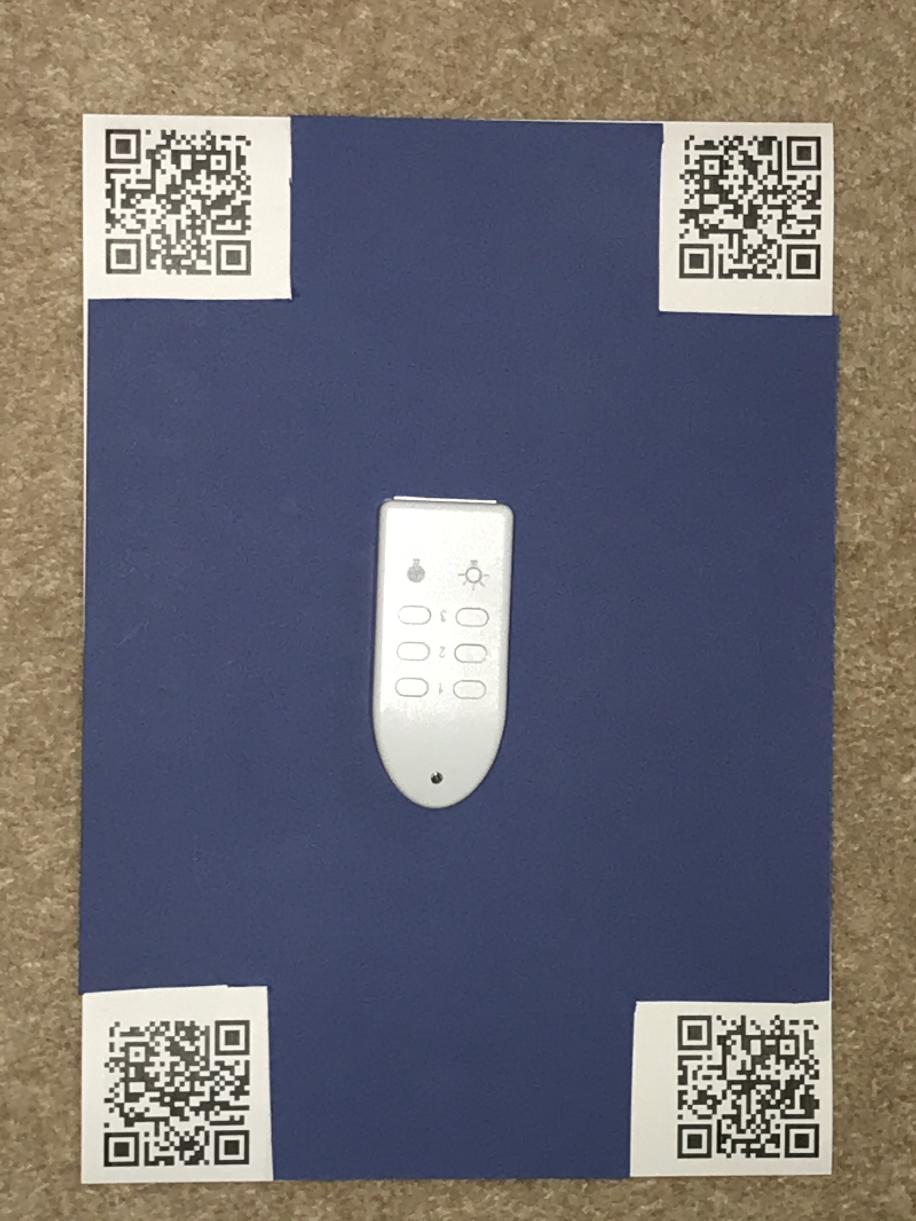
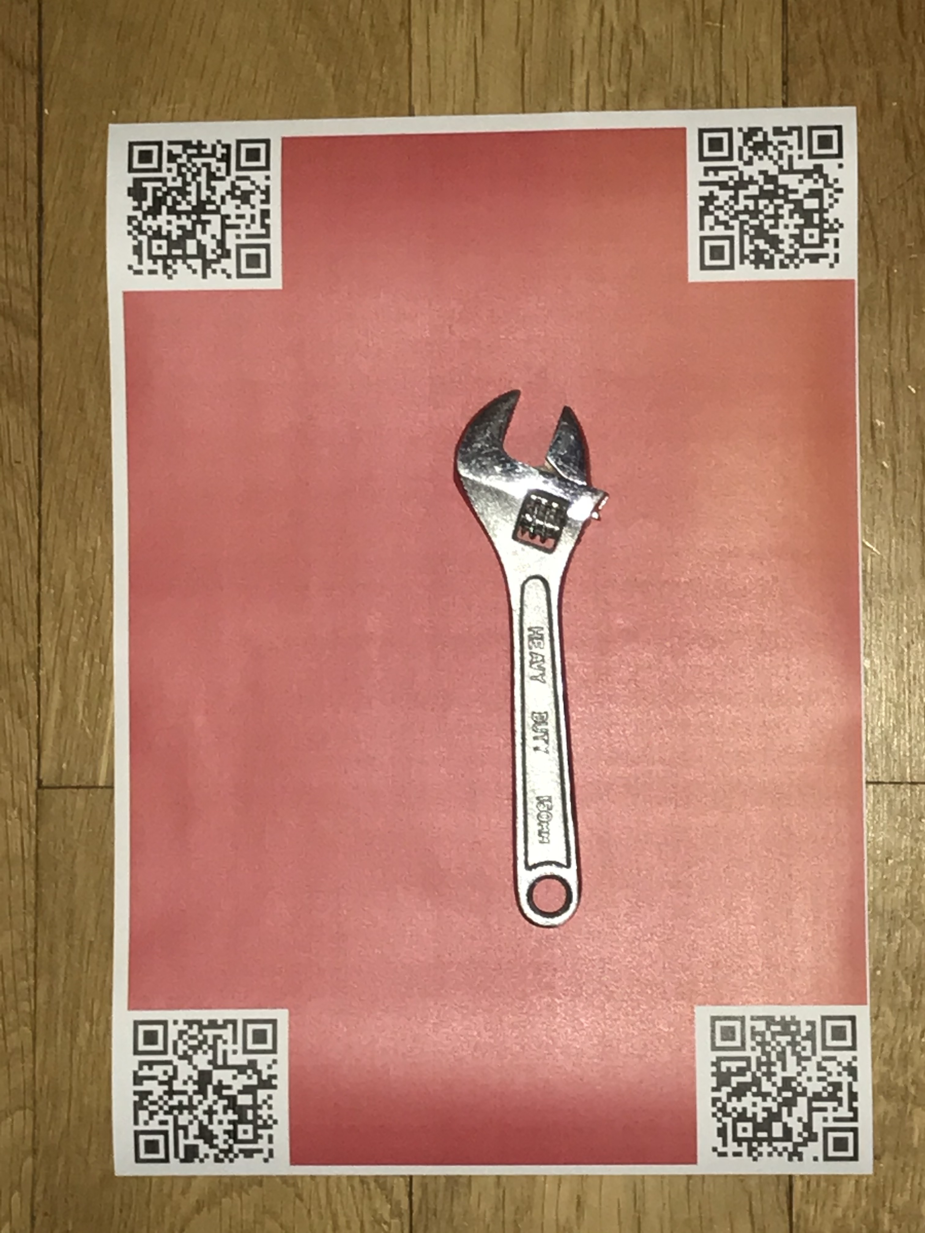
As it happens, I’ve been contemplating this problem a bit lately. It should be possible to have some 2D barcodes like Aruco tags printed on some green construction paper and have an automated workflow, starting from a single image, performs geometric correction based on the tags and then chroma keying or something similar to extract the outline of the tool. Ideally it could be 100% automatic and export a black and white png at a fixed true scale DPI. Then it would be straightforward to import into inkscape at that DPI and trace. It needs to be extremely streamlined or else I will do just a couple tools and get sick of it and give up on the rest.
My box is just like that outlines no cuts I just lay the tool back where it belongs I never even considered cutting them I’ll lose the darned thing then and never have another
It’s a combination of software, some stuff we wrote, some things we brought and some open source software. There’s currently seven steps to get to the PNG, the last step, step 8, is going from the PNG to SVG.
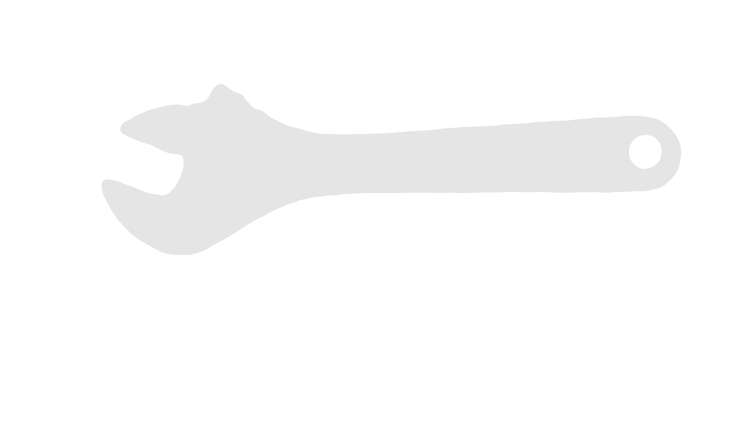
It actually works by using a series of 4-6 user provided photo’s each taken at a slightly different angle which are combined to remove shadows, to do edge detection, specular reflection and other stuff. We have different backgrounds for different things. Metal works well on red, but different objects requires different backgrounds. We then work out the best edges and generate accurately sized SVG files suitable for inclusion elsewhere.
The aim is to generate SVG files quickly and easily from users with a streamlined process. This requires significant CPU’s to work. It’s very, very CPU and core intensive, though we are investigating AI processes to see if we can speed it up and get better accuracy. Shadows are a major pain as is reflective metal
Generating the SVG is also hard work for curves as we want to generate the correct Bezier curves. I can state with some authority (and an increased credit card bill) that none of the applications on the Mac app store work reliably, so we’re looking into doing our own. This is yet more work
We may release it in the future as part of a free product but at the moment, our focus is on
Surviving Covid-19 by keeping the income coming in. The core business is PM & Consultancy and so far it’s holding up.
Working on a front end that uses this output and will integrate with a CNC machine. We are building a PoC and have just lost two days being side tracked by Typescript integration. Grrr…
You might get better results for less engineering time with AI. But if it were me, I would focus on putting the work on the GPU. Using Cuda or opencl. At a minimum, I would expect all of your massively parallel tasks to end up at 20x faster. If things like edge finding can be done one pixel at a time, those can run in parallel on a nifty nvidia gpu and they will get done real quick.
There is a tool we used in sandify to make svg bezier curves from a list of xy points. We are using about 1% of the library. It seems very mature. It is d3js.org, I think.
This would be a killer tool with a web front end and a backend running on a gpu enabled server. People print their patterns, upload the photos, the photos go to the backend and get churned, then the XY comes back to the front end for some touch up by the user and to use the user’s cpu for the final stages.
That sounds very interesting for me the marker works fine and at this point have no need to cut like that but it’s nice to know the tec is there hope it goes well for you
I am surprised it consumes so much CPU. Aruco tags are probably much faster than QR, and I would have expected the resampling and chroma keying to be fast too. The final step, converting a binary image to curves, I suppose could be achieved by integrating potrace directly, although one manual Inkscape step would be tolerable for me.
It all adds up, multiple photo’s, multiple steps, real world photos taken with real world cameras are not nice and neat, We have to handle flash, darkness, different focal lengths, different sizes. We have to do a lot of work to try to make everything usable.
The aim is not to have to do that final Inkscape step at all and to have a dimensionally accurate and usable picture for integration further downstream.
We know Linux from the days when we downloaded 25 5.2" inch floppies via UUCP from the US. Yyradsill (or something). Thats our preferred server development.
We have a lot of Linux on local servers as well as prod servers out in the wild. We don’t tend to use them for client side stuff as the interface is still poor after 30 years compared to a mac or whatever. However for command line, we’re find with emacs and a shell.
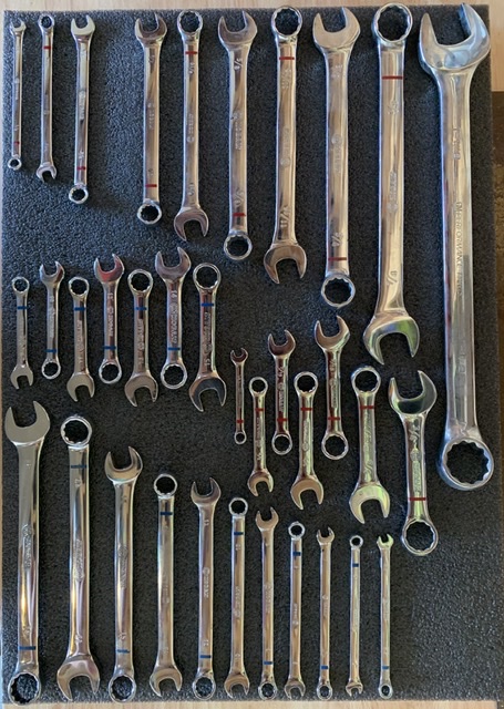
 I never even considered cutting them I’ll lose the darned thing then and never have another