Yeah. That doesn’t sound too good.
Jeff, if there is anything I have learned from this forum, it is that you can fix everyones problems!!! This isn’t looking good. Guess I will be buying a new board. Back to square 1. Thanks all for the help!!
3 Likes
Alright guys, I am back with a new challenge. (sorry!) hopefully this one is simple enough though.
First of all, I bought an SKR Pro, so hopefully I don’t run into the problems I had with the Turbo.
Second, I am trying to figure out these endstops so that I don’t fry something on my new board. The endstops I am trying to use are the ones on the old printer frame. I would like to re-use them because they already have all the wiring nice and tidy and the other ones I have seen are just too large. If you guys think I should just find some new ones and make my own endstop boards to fit the frame, let me know, but I wanted to get some input first since that seems like a lot of work.
The endstops are these guys:
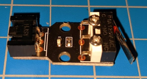
They have a little LED and a resistor. What I am used to is only using a NC switch and no NO side. That way if a wire breaks, it stops rather than keeps going. So why would this endstop have both NC and NO used? Is it due to the LED? Any suggestions on how I would go about re-using these with the SKR board? Seems like it has 3 pin endstop connections already. When I type in 3-pin endstop, I get a lot of different results but nothing that has helped me so far.
Thanks!
The NC/C switches assume that you have a pullup resistor on the mainboard. These usually use the resistor/LED to pull up the signal pin to 5V when triggered, so they work even if the pullup resistor does not.
They will work with only NC/C connected. to (-) and (S) The circuit still does the basic job of keeping those connected until the switch is triggered.
It’s a very simple circuit, the resistor and LED are connected to (+) and the LED lights when the stop is triggered. It’s kind of nice to have for a visual diagnostic that the stop is connected and working. I have many generic RepRap stop switches with the same circuit. I do like the visual feedback, which also tells me that the stop is properly powered.
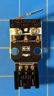
Ok, so how to figure out which pins to connect to (-) and (S)? If I use the multimeter and the below image, here is what I get:
I get an open between pins 2 and 3 when the switch is not activated
When I press the lever down, it becomes 4 Ohms between them 2 & 3.
Red on pin 1, black on pin 3 I get the LED to light up with switch open.
Red on pin 1, black on pin 2 I get the LED to light up with the switch closed.
If I switch the red and black leads, the LED does not light up.
Trying to talk myself into the answer here. If I want to use the switch as NC, then I should use pins 1 & 3? Any reason to keep the NO side plugged in? And which pin would go to (-) and (S)? I thought messing this up could fry the board, right?
you should get continuity between 2 pins with the lever NOT pressed… But it sounds like this is configured to use normally open logic.
Assume that pin 1 is (+) this makes sense with what you’ve shown.
I believe that the signal pin is most likely pin 3. which will be connected to the (C) pin on your mainboard. (You can see the “C”, “NO” and “NC” labels on your switches. There should be continuity from each of these to one of the wire pins with the switch both triggered and not triggered. Check this!)
I believe that “C” will be connected to pin 3, “NO” will be connected to pin 1, and “NC” to pin 2. (I might be wrong. Check!
In which case, (+) should connect to pin 1, (-) should connect to pin 2, and (S) should connect to pin 3. (+)/pin 1 can be left out, and the LED will not light. (This should match the order on the SKR board, as well as most RepRap boards, like the RAMBo, or most RAMPS clones.)
1 Like
Those boards are NO. They cause lots of confusion. The common advice is to remove the switch from the board and use it directly.
Also, the endstops are ignored during most operations. They are only used during homing. But the machine doesn’t hurt itself when it hits the end.
2 Likes
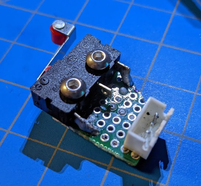
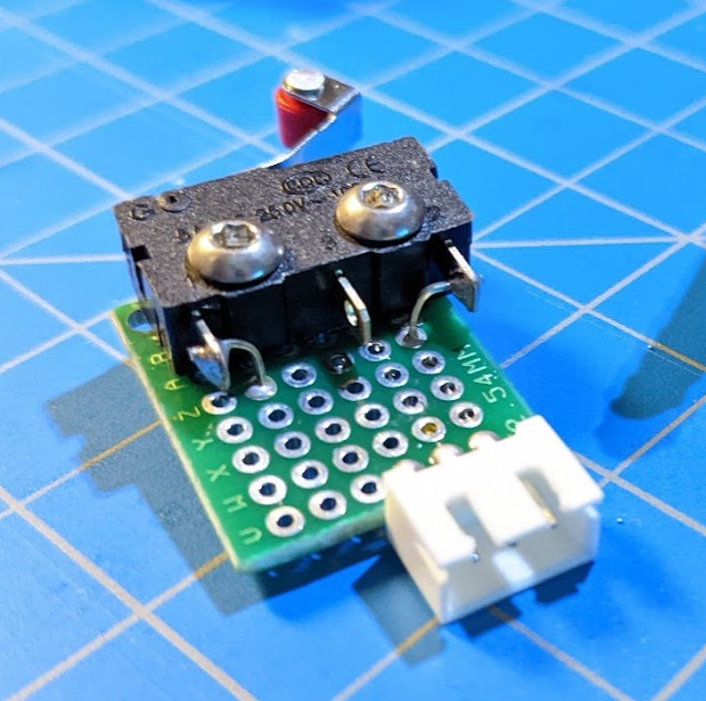
Well based on Jeffs advice, I grabbed some perf board I had lying around and built my own little endtop board. It has the 3 pin plug, but the 5V from the SKR pro will go unused. Unless I can use that to light up an LED??
Its not pretty, but according to the multi-meter it works. I am a noob with electronics/soldering so please tell me if any part seems like a bad idea!
-Mike
1 Like
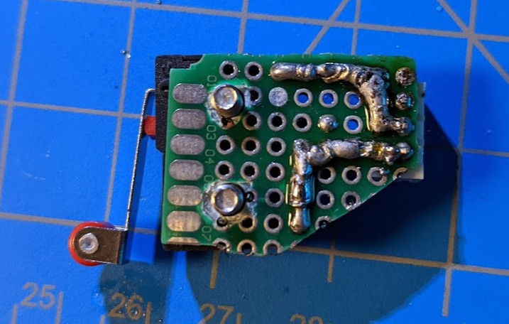
At first I was proud, but looking at these pictures, a little embarrassed about my handiwork 
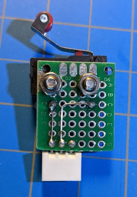
Second one looks better, but usually I just solder the wires directly to the switches.
that was the plan originally but since I am using the remains of the old printer, I decided to not mess with the existing harnesses since they are nice and being able to swap switches easily is a plus. Also, the mounting locations for the old switches are being re-used, so the board thickness helped get the switches lined up a bit better. If these janky switches fail, I might reconsider, but hoping we are good now.