Custom keycaps

One of the reasons why I built the MPCNC was to make custom keycaps and keyboards.
This is my first test with just cheap poplar plywood I had laying around. I had to make a custom fixture to do the clearance pocket inside.
[attachment file=98255]

Toolpaths: I used an adaptive at 1100mm/min, 1.5mm DOC with a 3.175mm two flutes bit, and a finish pass consisting in a parallel pass on the curved top, and a ramp on the sides, with a 4mm 2 flutes ball endmill, at 1500mm/min.

The backside was done with the same settings, without the parallel finish.
[attachment file=98256]

the cap was held in a custom 3d printed fixture that fit the part precisely, and then held on with a custom jaw. kinda small, but easy to use (it aligns to a bolt pattern I cut on the wasteboard so I’m always sure it is square).

Now I just need to make the stem, which, because of the really small sizes and tolerances (has to both fit the switch stem inside, while at the same time fitting inside the switch when it is pressed) I’m having a really hard time 3d printing it without many compromises, so I may just get a 1mm endmill and cut one out of plastic, then cast it in resin for future pieces).

Now, I need to optimize the cut to reduce toolchanges (3 total), and then try it in hardwood, as was planned.

I can not wait to see the finished part! Sounds like you need to find a buddy with an SLA printer to make the master for you, unless a small endmill will get all the detail you need? Either way those are going to be some nice looking keys.

Nice. You’ve really embraced the idea of having and using home based CNC machines. You’ve combined additive and subtractive manufacturing, toolmaking, and the overall process flow of creating. I also look forward to seeing your finished keyboard.

This is very interesting to me. Please share as much as possible. I would love carving custom keycaps. Can you make them in bigger batches?

So are you thinking of printing the stem and gluing it in a cavity on the bottom? You might save a ton of time if you can use a forstener bit to dut the hole in the back to fit a printed part. With the right fixture and even a benchtop drill press you could do 50 in about 30 minutes. Of course, then you have to make sure they are rotated correctly when you glue them in.

Are you planning on adding labels? A V bit or a laser would make quick work of that too. You could even add labels on the front (for different layers or just to keep the tops clean). You could probably sell these for a small fortune when you’re done.

Thanks. The stem is actually quite a simple part. A small cylinder, with a cross inside. The cross arms are around 1.2/1.3mm wide, and 4mm long, while the cylinder has a 5.something mm diameter. So really easy to cut, as long as I have a small enough bit. I could use a resin printer though… Maybe in a couple months.


[quote="jeffeb3,post:4,topic:10216"] This is very interesting to me. Please share as much as possible. I would love carving custom keycaps. Can you make them in bigger batches?

So are you thinking of printing the stem and gluing it in a cavity on the bottom? You might save a ton of time if you can use a forstener bit to dut the hole in the back to fit a printed part. With the right fixture and even a benchtop drill press you could do 50 in about 30 minutes. Of course, then you have to make sure they are rotated correctly when you glue them in.

Are you planning on adding labels? A V bit or a laser would make quick work of that too. You could even add labels on the front (for different layers or just to keep the tops clean). You could probably sell these for a small fortune when you’re done.

[/quote]

Ok. So, basically the toolpaths are as I explained. I don't remember the stepover, though, but something around 0.2 or 0.3mm. nothing special there.


Bigger batches are actually easier. I just take the slab, leave a few tabs and reverse it with two alignment pins. However, the way I see it, batches are great if you plan to keep continuity in the grain, which means I need to model all the profiles and special keys first. So I started the harder way, with the single piece and fixture, since I could also use it for artisans with more milling ops.

The stem is going to be printed or cast, and glued, yes. However. I’m milling the pocket directly, because a simple circle won’t do for clearance. So no need for a drill press (which I don’t have anyway). Alignment is something I need to think about, since the pocket is rectangular and not square, it shouldn’t be hard, but I need a really precise stem “plate” that fit into it. I’m not milling the stem directly, because wood is going to break, or so it happened to everyone that tried.


About labels, yes, I’m going to put some. I was thinking about vbit engraving the letter or symbol, and then filling it with brass powder and CA glue. While laser would also work, brass works best for the aesthetic I’m going for (the keyboard will have a brass plate too).

However I still need to do a few experiments there, I didn’t on the plywood piece because it’s way to soft to hold such small details. Which is a pity because I’ve got some new pyramidal vbits I wanted to try.

1 Like

Thanks for the info. Where did you find the CAD for the profiles?


This one I modelled myself quite a while ago, from some other reference I don’t recall.

Geekhack has a a repo that contains PDF’s with measurements for all rows and profiles, here: GitHub - mohitg11/GH-CAD-Resources

Also, there are multiple repos with cad files already made, I just downloaded from the one I linked at the start of the post (because that’s where my phone is placing them when I paste and I’m going to mess it up copying it by hand) to have at least a full profile around, but I haven’t chosen a profile for my own keyboard so I didn’t do anything with them yet.


2 Likes

So, almost a year later, I went back and made a full macropad.
It’s not 100% complete, since I need to print 2 stems that have broken and my printer is out of commission at the moment. But here is where I am right now:

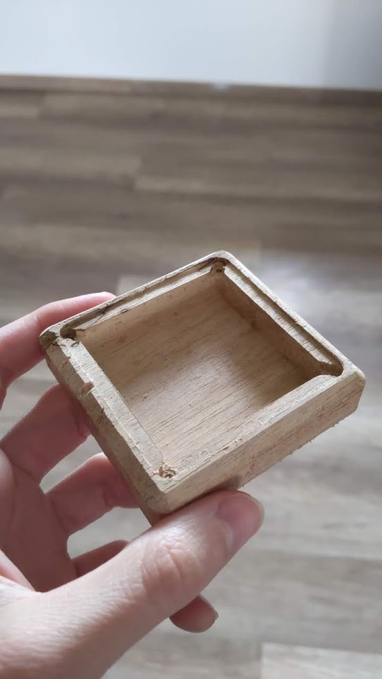
First came the case, a simple square with rounded edges, a pocket, and a chamfer. The hardest thing would have been the chamfer, if I didn’t do it with a router bit by hand.

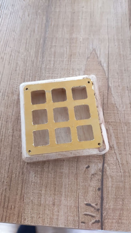
Then came the brass plate. This one was harder. Even with a more rigid spindle than my old one, there still was too much flex. The holes are undersized by quite a bit, around 0.5mm.

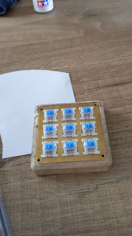
After some work with a file, I have bigger holes and a much less straight matrix. This will get solved later on. Time for the switches to get in.

As you can see, they are all crooked. Luckily, this can be fixed with the stem system I’m using.

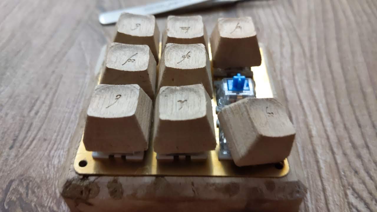
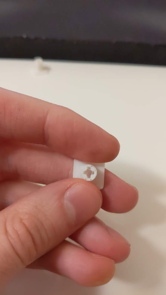
Now, time to make the caps. Since I’m making 9 of them this time, no need for the custom vice to come out. I start by milling the underside, leave 4 1/8" semicircles that will fit a broken endmill later on, and alignment is done. Workholding is provided by superglue and masking tape.

Then, time to engrave some Tengwar legends: https://photos.app.goo.gl/najAw18LD2vR1xuR6 (video on google photos)

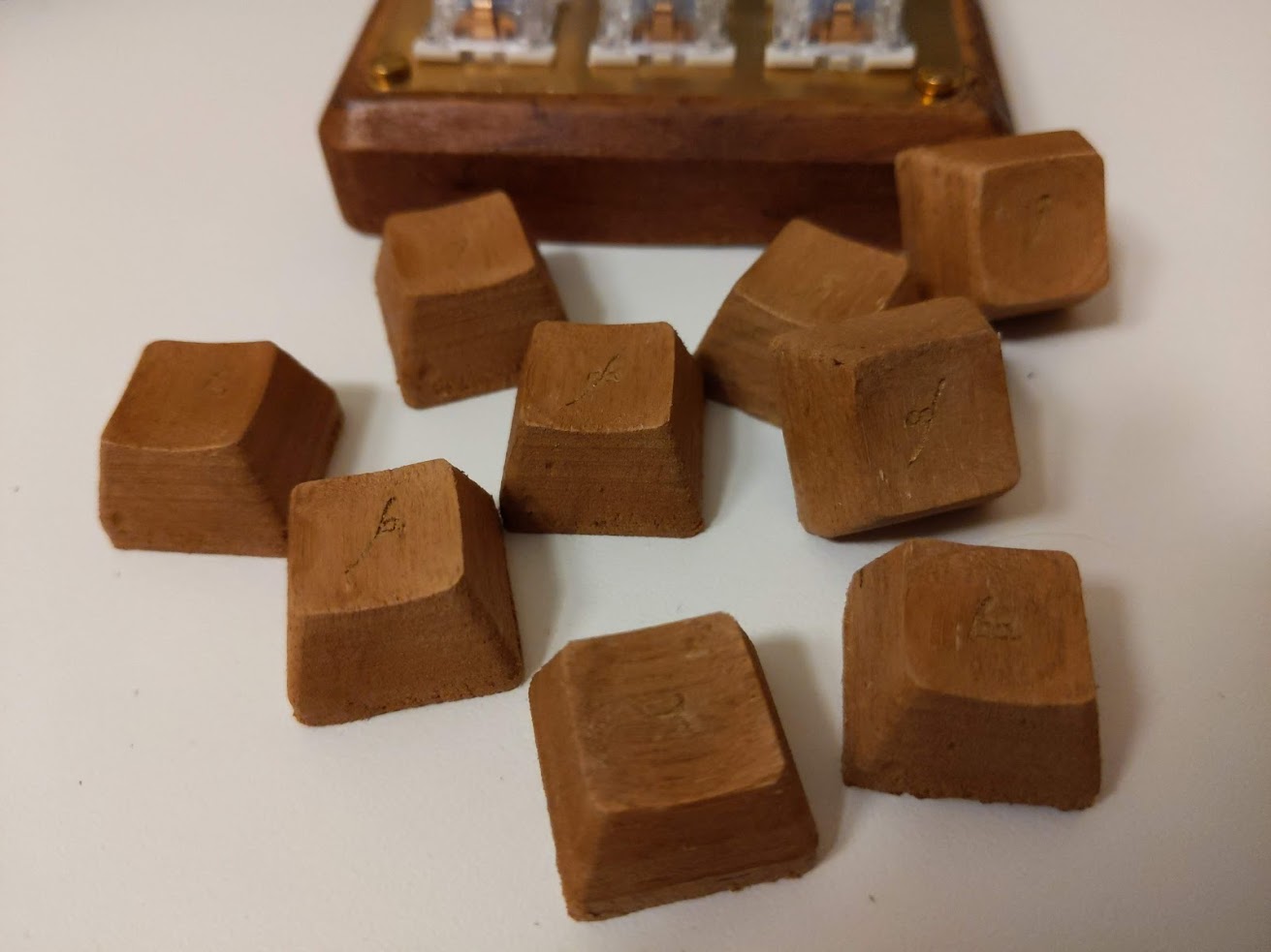
and this is everything on the keyboard.


Also, the printed stems:

when I say I can fix the crooked switches with the stem, I mean that I can just make the stems undersize instead of tightfitting in the cap pocket, and glue the cap (with doublesided tape) straight, ignoring the actual alignment of the cap underneath. I haven’t done this yet, though, because I need all the stems to be ready before committing. With the situation in Italy being what it is, it will take a while for amazon to send me my printer parts. But the hardest part of the job is done, so whatever.

However, I decided that walnut isn’t good looking enough, and had to ruin it. this is the mess that came out after staining (and adding some gold paint in the legends):

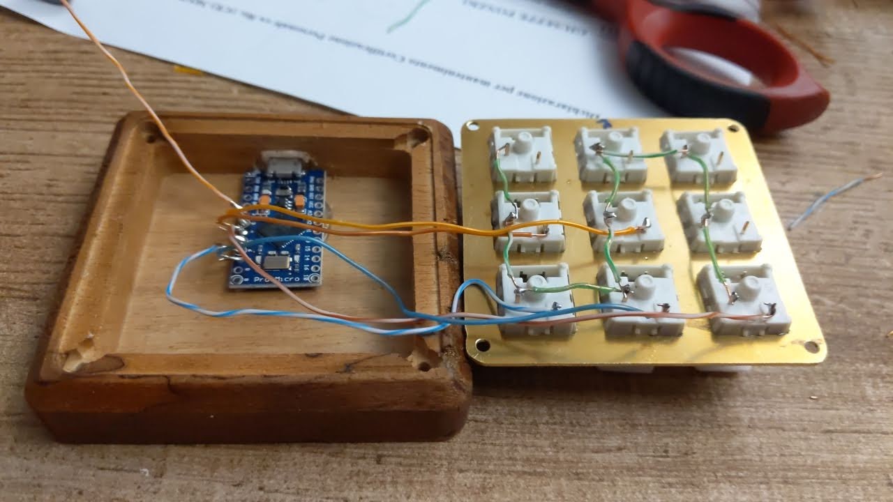
Also, some soldering required:

So, this is where I am: I have functional keycaps and a working macropad, just with the last bit of assembly to be done.
I definitely see this as a success, even though I think the stain ruined it a bit. At least it worked as a proof of concept for continuos grain keycaps set, which was the thing I really wanted to test out.
Each caps is only 4.3mm away from the next during machining, so material waste is pretty minimal. and even with really small legends, the engraving worked out. I will need to change my filling techniques, probably using epoxy resin and a pearlescent dye with the part still in the machine, and then repeating the finish pass to clean up. It will be the next thing I test, once I can go out and buy stuff again.

Just one last, obligatory thing, for a mechanical keyboard-like object: Sound check. Im using outemu blue switches, so don’t expect much, but I still think it sounds nice:
https://photos.app.goo.gl/axy77Sr6gantre8L6 (video on google photos)

6 Likes

What a neat project. Are the caps interfering with each other a little? Like, are they a bit too wide?

I think this is very functional, and there are a lot of great uses for this keyboard. It is so close on a couple of details before it would be an epic result. So I would call it a huge success. For one, it freaking works and looks good. And you have learned enough that the next one will be even better.

No, the caps have around 0.2 or 0.3mm clearance between eachother. The plate has standard spacing, and the caps follow the SA profile standards (kinda. Height and angles are chosen by me, but width and radius of the spherical top is standard), so there is no risk of intereference.

I’m actually struggling with how to use it, though. I wanted to dedicate it to controlling the cnc for zeroing and stuff, but cnc.js doesn’t allow you to change jogging resolution with shortcuts, so it would still require me going and using a mouse to change it. Not optimal. Also, I need to implement macros in the firmware. I initially wanting to use QMK, but I realized I don’t have enough patience to figure out all the issues in the toolchain on windows and make it work, so I made my own , but right now it’s too basic and can’t send key combos. Also need to make it configurable through the serial port.

And yeah, the next version will need just a couple of adjustments. A better wood is one, something a bit denser and that cuts cleaner. And of course a plate that’s straight. But I’m still quite happy with how this one came out.

If it is only for the cnc, then you could change it to send gcode over serial and skip cnc.js altogether.

1 Like

That was plan B when i realized I didn’t have any pro micros on hand, to just use a Nano and a UART port on the mega. But it would lack feedback on the chosen resolution, and I liked the fact that I could have used as a macropad too.

If I can’t find other uses for it, I will probably make a cable for that, and add a dip switch or something underneath to switch between the two modes