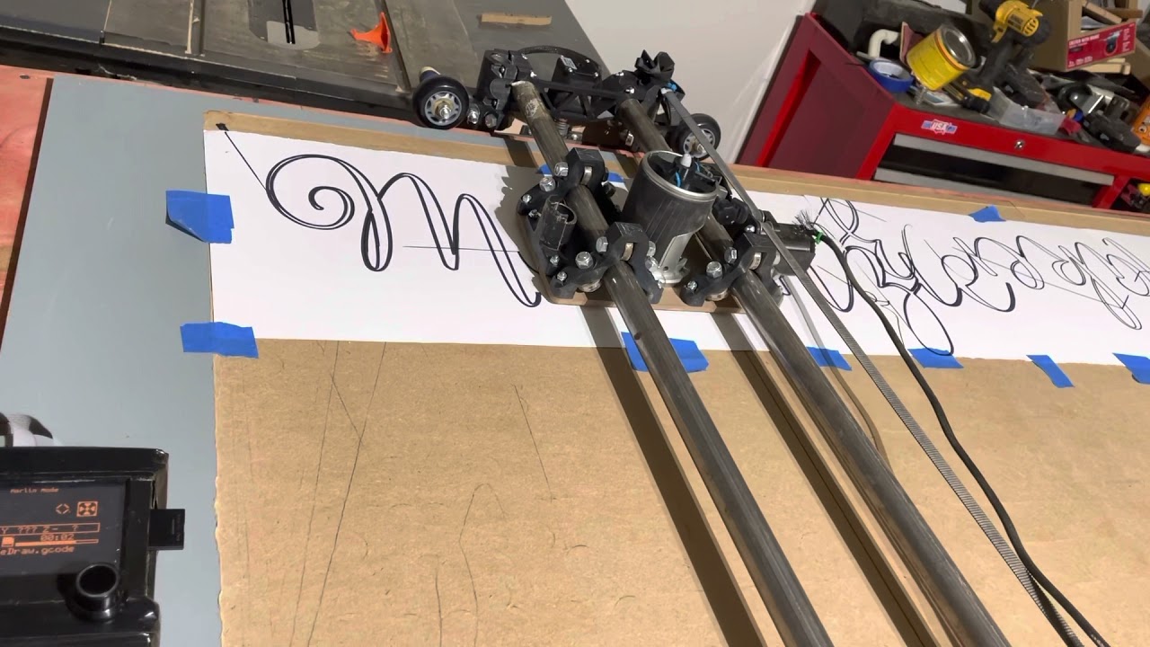
So I am trying to cut out my daughters name; and wanted to test the cut by drawing it first, the gcode would be the same for both runs , with the depth for the cut being 12.75mm rather than 1mm.
I have uploaded both sets of GCode; I am sure it is just me missing a setting in ESTL or not putting gcode in.
I have also attached a link to the video of the test run.
The paths I am referring to are to the top left of the “M” ; the middle of the “M” and from the “A” to the “K”.
I think that it is the Z axis not coming up high enough to clear the top , or could possibly be my Z axis is not planer(I thought it was).
Thanks again for the help. This forum is awesome!
MakenzieDraw.gcode (167.8 KB)
MakenzieCut.gcode (2.1 MB)


