Keeping everything “the standard way”, Z homes up and Z touch probe is down. Endstops are set up like so (you need 5 wires and 5 endstops – one per motor):
THANK YOU FOR THAT REPLY i really appreciate your help
so for the z home plate. im pretty sure i have all the pieces…
is there documentation on how to wire and hook up the z home plate?
sorry for being here with all the questions… i read through so much documentation ive gotten myself tangled up in thought lol
and im very new to the builder space this is actually my first project… so bear with me i beg of you lol
so i need to move my ystops off of the left z plate? i watched a vid from the “teching tech” guy and i had printed out these special parts that mounted to both sides of the left z plate. teaching tech lowrider end stops thingverse endstop parts
so lets just say i couldnt change from where i am at… to the standard way of setting up endstops
what kind of work am i looking at? reconfiguring firmware etc etc?
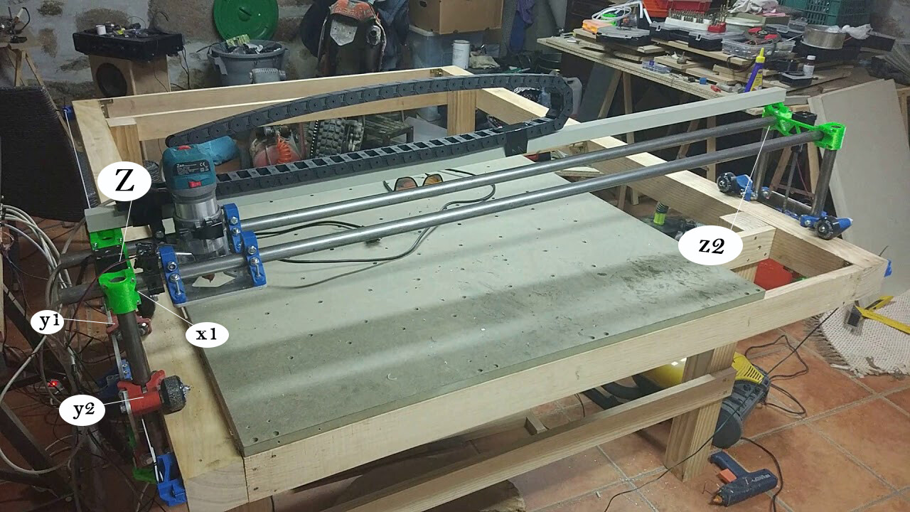
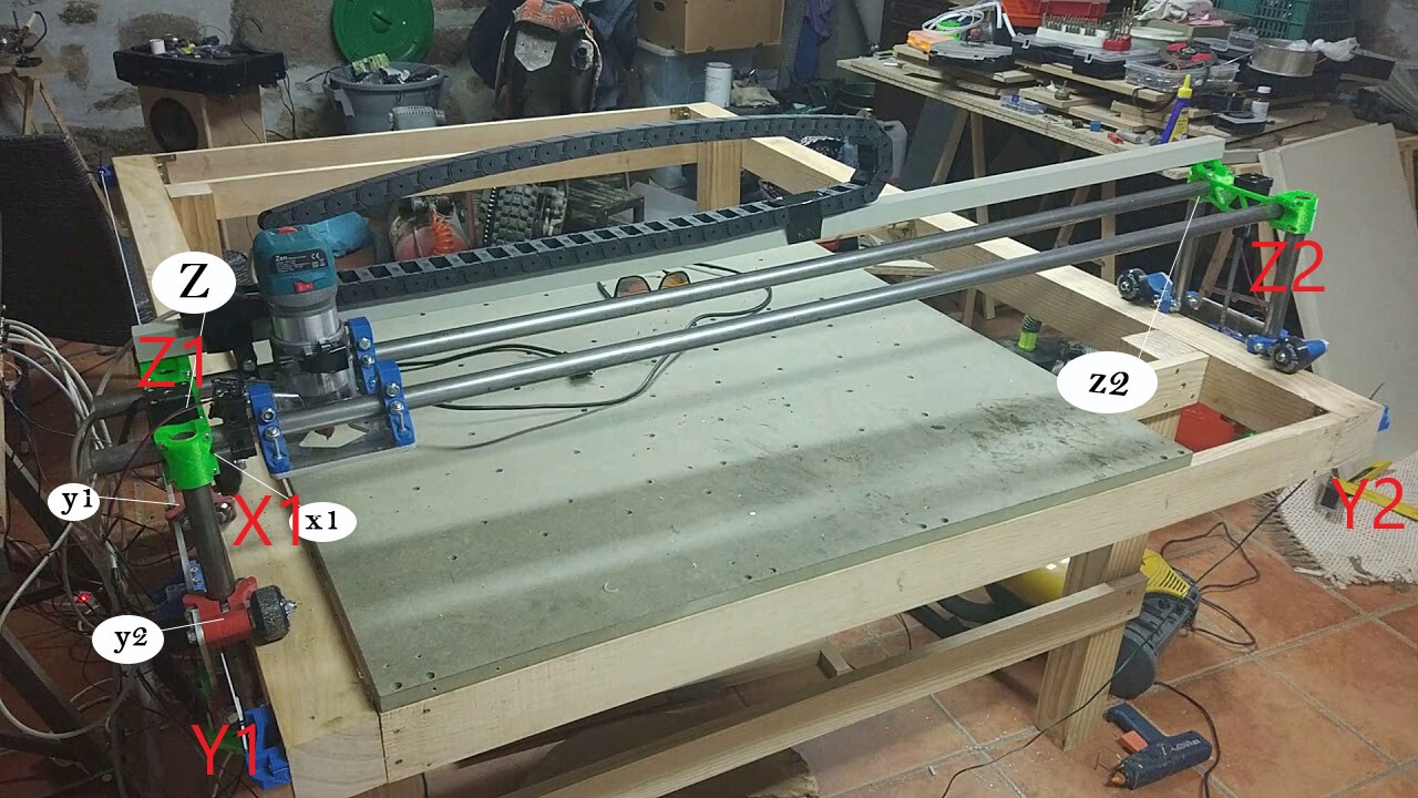
I’m answering “fast” since I’m here, but I don’t have a LowRider, so someone may come along and correct me. My following comments assume you’re machine origin, or 0,0,0 point is at the near left-hand corner with the tool touching the work surface. X axis is “across the table” left-to-right, Y is the long axis front-to-back and Z is up and down. This isn’t necessarily where you’ll put your workpiece, but it is the reference point for the machine itself.
I believe the V1 firmware for LowRider is configured for auto-squaring, so it needs a Y end stop at the minimum end of each Y rail. This means moving Y1 to the other side of the table, mirroring the current location of Y2. And making sure the Y1 motor and the Y1 end stop are on the same side. While doing the final commissioning of the machine, you’ll build a correction factor into the homing routine so that the machine hits the stops at each end, then automatically tweaks one side so that the Y axis ends up square to the X axis.
(The way your picture shows, you have the Y switches right now look to be set up to act as Y min and Y max. Since Marlin firmware generally ignores limit switches, there’s no real point to having a Y Max unless that’s where you want to home the machine to.)
The two Z end stops, one at each end, can allow for Z “auto levelling” so that the X axis ends up parallel to the work surface, but I don’t know whether the firmware is configured for that “out of the box” or needs to be tweaked.
hey tom thank you for the reply and ive taken your advice into conideration and started to reconfig everything
ive run into a new problem here… kind of has my mind boggled lol
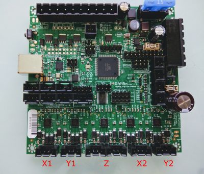
so according to this pic with firmware V1CNC_Rambo_DualLR-2.0.9.2
the y2 should be the last stepper plug.
but somehow x2 has become y2 and y2 has become Z
that just threw me for a loop everything has its own independent wires…
any help?? could i need to do a reflash?
so i just did a reflash
i plugged the y stepper into Y2 and i did a motion test on z access and the y motor moved… its currently the only stepper plugged in also…
OK so i got the x and the y to home… i feel so accomplished
although things got murky quick lol
ok so i went to home the z access and only one side wants to home up
so heres what happening
home z with no z end stops plugged it moves down for a quick second then stops
home z with only z/min endstops plugged it moves down a for quick second then stops
home z with z/max endstops plugged in … only 1 side of z moves
ive tried reversing the z stepper wires and i also flipped them
still nothing changed but the direction of the home. still only tryed to home one side with z max plugged in
The endstops for Z aren’t Z_MIN and Z_MAX. Z_MAX is the stop for X1, Z_MIN is used for the Z probe. I’m not 100% on this, but I think that the endstops go:
X : X_MIN
Y1: Y_MIN
Y2: Y_MAX
Z1: Z_MAX
Z2: X_MAX
Z Probe: Z_MIN
If you don’t have a switch plugged in, it reads as triggered, so Marlin will go backwards about 5mm and stop. (It goes to triggered, backs off ~5mm and then goes more slowly to triggered. Since it starts triggered, you only see the back off move.)
Use M119 on the terminal to check the endstop status.
for the LowRider, homing upwards is probably better, because the length of the router bit is an unknown, so it’s not guaranteed how low each Z axis can go. For the Primo, there’s only 1 Z motor, so you can home until the bit reaches the spoilboard (or material) but you can’t do that with the LowRider, unless you assume that the motors are guaranteed square. Since homing is really squaring, it’s better to home to the safe position, then use the probe to determine zero.
So, either do something to guarantee that the Z motors are level, and just use the G382 probe function to zero the machine, or home upwards. Homing downwards might be OK if you make a mechanism where it can go past the limit switches, but otherwise, you do run the risk of crashing the bit into the spoilboard.
Edit: Yes. X+ should be to the right, and Y+ should be away. (This assumes you;re standing with the LR gantry spanning from your left to your right, not standing beside the Y plate.)
thank you everybody for your help i had to take everything apart… and rewire to a new board
but i went over the entire thread and i did everything correctly because of all your help so THANKS!!!
just a couuple more questions
i have a big table its bigger than 4x8 by a few inches
do i need to measure the table and entire the calculations inside of one of the programs or something
because when i tell it to home if its too far away it will say homing failed?
if i move it closer it works and will home correctly though is this normal
It is these two defines in configuration.h that set the bed size (in mm) for your machine:
#define X_BED_SIZE 600
#define Y_BED_SIZE 600
Your current values are likely to be different than the ones listed here. To fix the problem, you will need to set these two values at, or larger than, the size of your machine, then recompile and reflash the board. Or you can just drag your core closer than whatever these two are currently set at before homing.
Other than homing, the only other thing I can think of that uses these values is max software endstops, and they are not enabled in the V1 maintained firmware. So, leaving these values alone and just moving the core before homing is a safe choice.
There is a defined bed size in the firmware. Changing it can only be done by recompiling the firmware, it can’t be changed on the fly. V1 firmware defaults to a size of about 2’ (600mm IIRC) so as long as you’re within that, you’ll be fine. I think the LR dual endstop firmware defaults to 200mm Z height.
Since the motors are unpowered, it’s easy enough to push the gantry to that corner of the table before homing. (Or, just move it back there. from the terminal or LCD.) Soft endstops are not enabled by default and it has no effect whatsoever on any jobs that you do. It does not limit maximum travel (Or minimum, You can go to huge negative space, too.)
thanks you guys i really cant tell you how much this thread has help me out with this project!!
you have answere all my questions in regards to wiring the lowrider up and some firmware bits i didnt understand…