Dear Erwin, Jeff, Ryan, global makers community. HOPE I FOUND YOU ALL SAFE AND WELL
I would like to ask your kind help with a recent project I have initiated earlier this week.
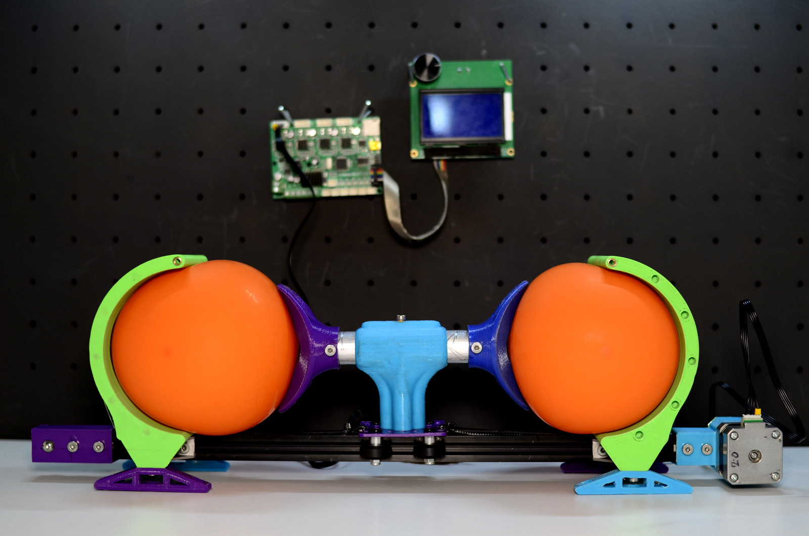
I am designing an open source dual operated (one setup for 2 persons) Auto ventilator machine hoping it could be helpful facing upcoming shortage of medical equipment, here in Israel as well as worldwide. there are many concepts out there, read more at google ambu automatic diy.
It will prove once again the power of makers community and a real time study case in the quest for ethical design. where the industry is slow to respond to market demand for respirator machine, the domestic fabrication unit can make the difference.
I am addressing you this issue since i have no capacity nor time to learn how to program my old ender3 mother board in order to create speed control and 1 directional movement. I have few more electronic parts i will later on send few more pics.
The configuration is set and based on a single step motor with dual action moving on one axis back and forth. should be simple!
image of setup
I have only been tracking the DIY ventilator issue from pretty far away. This is the first one I’ve seen with two pumps though.
Correct me if I am wrong (and I don’t want to sound negative), but is the problem actually the number of machines? I thought the real shortage was the number of respiratory doctors and teams that know how to operate the machines. I don’t have a source for this, but I thought that multiplying the number of machines wouldn’t actually help.
As for the direct response to your query, You could attach a belt to that gantry section, and with only a single axis for control, the code to manage it would be much simpler than CNC firmware. It could either operate in “open loop”, where the motor was just counting steps to determine when to turn around. Or you could put a micro switch on either end to let it “know” when it has reached an extreme. I do not know which would be more reliable.
An alternative mechanism would be a single motor in the middle, with a large eccentric circle attached. The eccentricity would make one side pump, and then the other. It would need a lot of torque, but the advantage is, you can ditch the electronics and just have an analog speed control on a DC motor to determine the rate of the pumps. Since the circle wouldn’t have to spin very fast, it could be geared down quite a bit to increase the torque.
But if you just want that motor to start moving, there is a good library used in the camera slider project that would work fine for a single axis machine like this:
I would ditch the LCD, at least at first. The last thing you would want is some interface to a screen causing a problem in the code, and crashing the machine. During development, you can just use the serial port to a connected computer, and parse simple commands, like sending a new total speed, or printing out information from the software.
What about a purely mechanical system, with a fixed center eccentric, and movable bladders…a simple hand crank could move the bladder towards/away from the motor, adjusting the air volume. No programming, no electronic display…one hand crank adjustment for each patient.
Also, @jeffeb3, they did say on the news that some places are using one ventilator shared between two patients because of hardware shortages. Certainly not ideal.
thanks Jeff for your super quick response, as far as i know, here in Israel we are facing shortage of machine as well as trained personal.
i am still review your answer, not sure i fully understand all options you presented, the learning curve is steep!!!
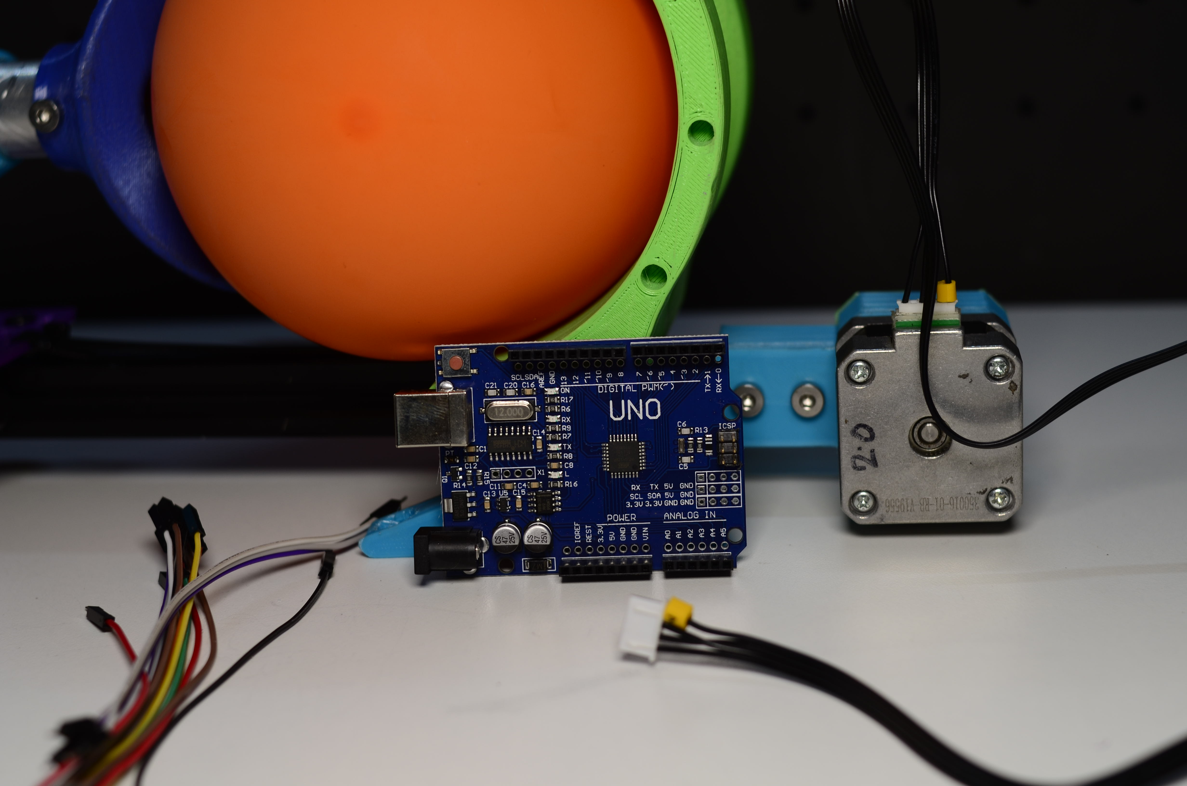
the gantry plate is attached to stepper motor with a belt, can i operate it just by plug it to ENDER3 M.B?
You can. As a software engineer with half a mind for safety, I may be being a bit too cautious. If I were making something that someone’s life depended on, I would be working hard to remove any unnecessary code from the software. Marlin (the code that runs on the ender MB) 20x more code than you need to move a motor one way, and then the other. Some of the code will actually be resisting your efforts.
Since most of that code is not worth keeping, it would probably be less work to rewrite just some motion code from scratch.
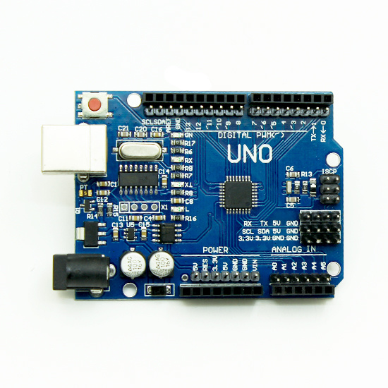
That is an arduino uno. That would work fine for running the software. And it is very common and cheap. The tutorials to use it are plentiful. But you would need a stepper motor driver attached to it. The ender board has a similar processor on it, but it already has the power distribution, motor controllers installed. The trick with the ender board is that there aren’t many tutorials for just using it to run whatever code you like.
the concept it based on AMBU low-tech device and to make it work with out anyone needs to operate it. in the prototype the ambu is presented with the 2 orange balloons.
// Bounce.pde
// -*- mode: C++ -*-
//
// Make a single stepper bounce from one limit to another
//
// Copyright (C) 2012 Mike McCauley
// $Id: Random.pde,v 1.1 2011/01/05 01:51:01 mikem Exp mikem $
#include <AccelStepper.h>
// Define a stepper and the pins it will use
AccelStepper stepper; // Defaults to AccelStepper::FULL4WIRE (4 pins) on 2, 3, 4, 5
void setup()
{
  // Change these to suit your stepper if you want
  stepper.setMaxSpeed(100);
  stepper.setAcceleration(20);
  stepper.moveTo(500);
}
void loop()
{
    // If at the end of travel go to the other end
    if (stepper.distanceToGo() == 0)
      stepper.moveTo(-stepper.currentPosition());
    stepper.run();
}
In this example, it moves 500 steps in one direction, then turns around and goes to -500 steps (for a total of 1000 steps).
Here are the questions you’d need to answer to use the ender board:
The stepper object here isn’t set up the way you’d probably need for the ender. I am guessing that the ender board will use a “step”, “dir” and “enable” pin for the motor. So we would need to find out what those pins are, and then set that object up to use them. Something like this:
Determine a useful max acceleration, and speed. These are in steps with this library, so there will be a little arithmatic to pick the numbers based on mm/s and mm/s/s:
Create a useful startup procedure, like making sure it starts in the middle, or adding in a homing endstop.
The ender may be using pins to adjust the stepper microstepping or current limits. If that’s the case, then we’ll also need to adjust the code to set that.
i get you, safety is at first priority, sure!! it should be simple as possible.
i am reading now your last reply, it will take me few minutes, thank you so much.
i know (from previous attemps) that the board can not be uploaded with new firmware (by directly connecting usb cable) but need some pcb i can not recall now in order to do so
You can reprogram (flash) the uno, no problem. So putting software on the Uno is easy. The trouble is, you can’t just connect the motor to the arduino. It will fry the arduino.
The ender has the right electronics, but it will need a bootloader to change the software, and then we have some mysteries to solve to make the software work on the ender.
So the possible solutions I see right now are:
Build up some homemade electronics around the uno. You would need to procure or already have at least one of the motor drivers (drv8825s, they are purple in the amazon images) that you can use. You would need to wire up a 12V supply to the driver, and the step, dir, enable pins to the arduino.
You can create an ISP programmer from an arduino UNO, which would be able to install a bootloader on the ender board. Then we could use the ender electronics and put new software on it.
You will be completely removing the existing software from the ender board. The bootloader replaces everything, so that would be a point of no return for the ender board.