In general I’ve found estlcam to be rather nice. The complexity is there if you need it, but there’s also simplicity for when you’re just starting. Honestly, I’ve not graduated far from the basics. What I’ve never really put much thought into is how estlcam decides to cut things (I’ve never altered the machining order for example), but a recent sign was a bit odd…
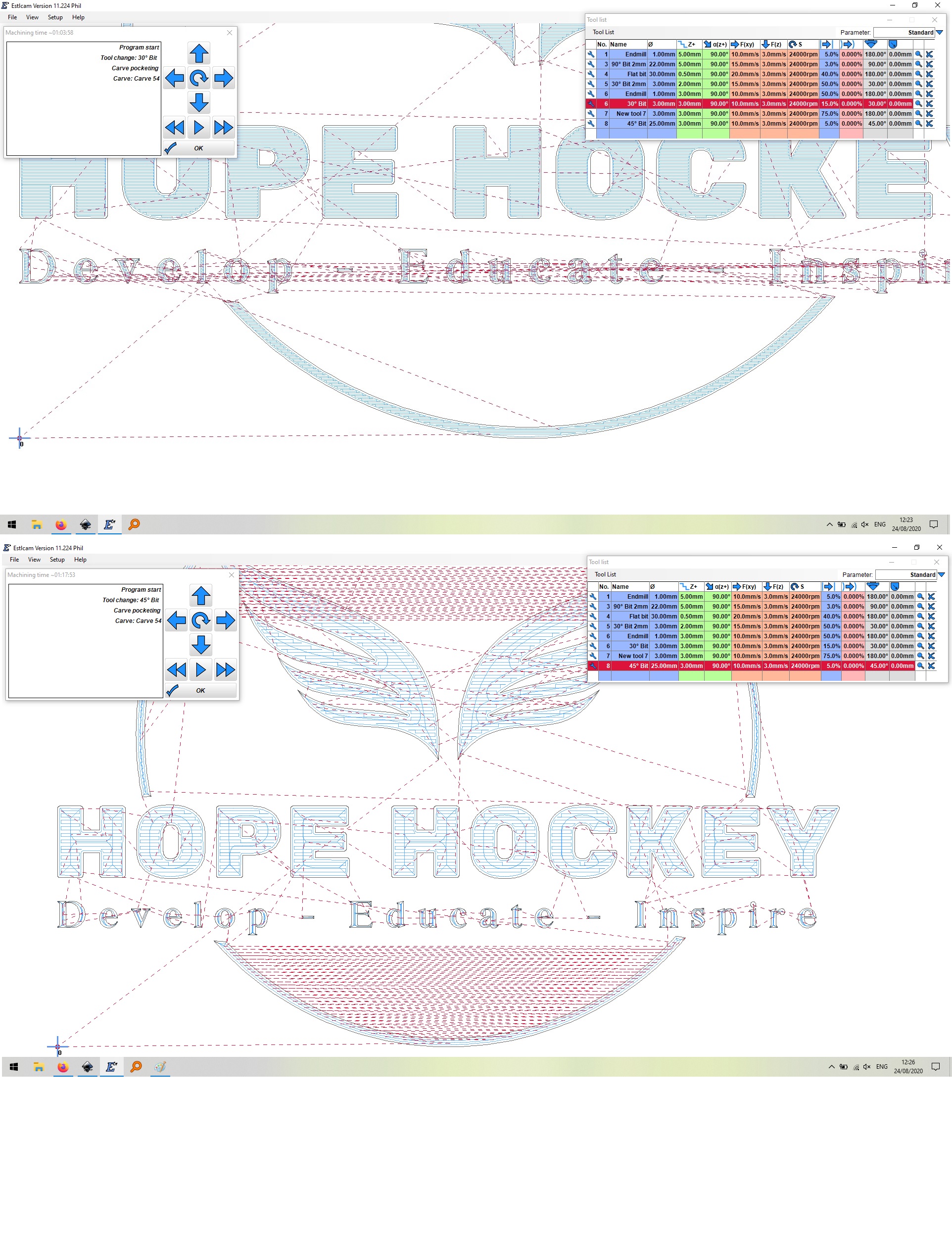
It seems like estlcam wants to move back and forward across the piece, but where this occurs depends on the tool I select. The top part is with a 30 degree V bit and the lower with a 45 degree V bit.
My first attempt at this was a disaster (but that was my fault), hence my inspection of the path. The first 10 mins or so were just the bit creating a slight hole within the bounadry of the bottom letters, then moving all the way acrossd the piece to do another. The actual cutting of the letters looked normal. Is this poor setup by me, an acceptable quirk of estlcam or a problem…?
It is a hard problem to solve, but the main reason it is just poking it and moving on is the separation between the roughing pocket and the final perimeter.
I have a feeling (but can’t prove it mathematically) that finding the one optimal path that is the single best and most efficient way to carve something is a ‘complex’ computational problem, akin to the Travelling Salesman problem. This problem looks at the most efficient way for a salesman (router bit) to visit all cities.
It’s classed as an NP-Hard problem which means and I quote “It is suspected that there are no polynomial-time algorithms for NP-hard problems, but that has not been proven.”
Any time I see an NP-Hard problem at work, I try to make it an SEP (Somebody Else’s Problem). The issue is that many people assume that computers are good at this sort of thing and sometimes they are not. I have struggled to explain to people that these sort of real world issues are incredibly difficult to resolve and you never know if you are close to optimal. A good real world example of this is I worked on a bid for the UK Census in 2006 and we had to plan walking routes for census people to follow up non returned forms (it’s a legal requirement to complete your census form). Management insisted that they wanted the optimal way for people to visit all the places they needed to and wanted to put a statement into the bid that this was the quickest and hence the cheapest, we argued long and hard to stop that going in as it was wrong and made us look foolish.
Now what we have here is a similar situation, intuitively we can see areas that we think would optimise the path that the cutting bit would have to take to make it faster, but there are lots of other things to take into account, such as acceleration, deceleration, lifting of bit, moving across the area to the new area. (Compare this to traffic lights, crossing the road, knocking on doors, back tracking etc).
A similar area is compiler optimisation to get the best possible combination of op codes to do the work needed. These are journeys through the CPU space.
A lot of effort has been put into optimisation of these problems by serious mathematicians with mad beards, chalk on their hands and leather patches on their sleeves, as this would save a fortune for USPO, Royal Mail UPS, code compilers and anybody else who has NP-Hard problems to resolve. If anybody manages to resolve them, they can expect a Fields Medal as the Nobel prizes don’t include Maths.
<TL;DR>
Now back to Estlcam, I think it does a reasonable job given the processing power available to it. Every time I use it I always think I could do it better manually but I don’t think it’s that bad.
Rob
If I were cutting 1000000 of something it may be worth optimizing but for 1 offs not a chance it would take longer to change than the time savings in most cases
Short Answer
Yes. I have the exact same sentiment as your quoted statement above.
Short Answer 2.0
Q: Do Estlcam’s paths ever look efficient to you.
A: Never!
Solution/Commentary
Allow me to elaborate:
- I basically make small signs similar to yours. I have grown into the habit of making my last step (after I have all the objects the way I want) to alter machining order. Yes, that may be 50 objects but I do it.
- In general, I find the time savings worth it and it can be drastic.
- Even though I approach each sign as a one off I find nothing is ever truly a one off.
- I just can’t stand the inefficiency.
I will make a couple more comments in the next post.
I appreciate that determining a tooling order is complex, but if you look at my picture, you can see, hopefully, how very differently the same shape is approached in each case. As far as I can tell, movement to create the lower curve (for example) is self contained, it starts and it finishes (with a finishing pass at the end of the whole job as Jeff mentioned). This is not a question of how disparate areas of the cut are approached, it about why the same shape is approached so differently with the selection of a different tool.
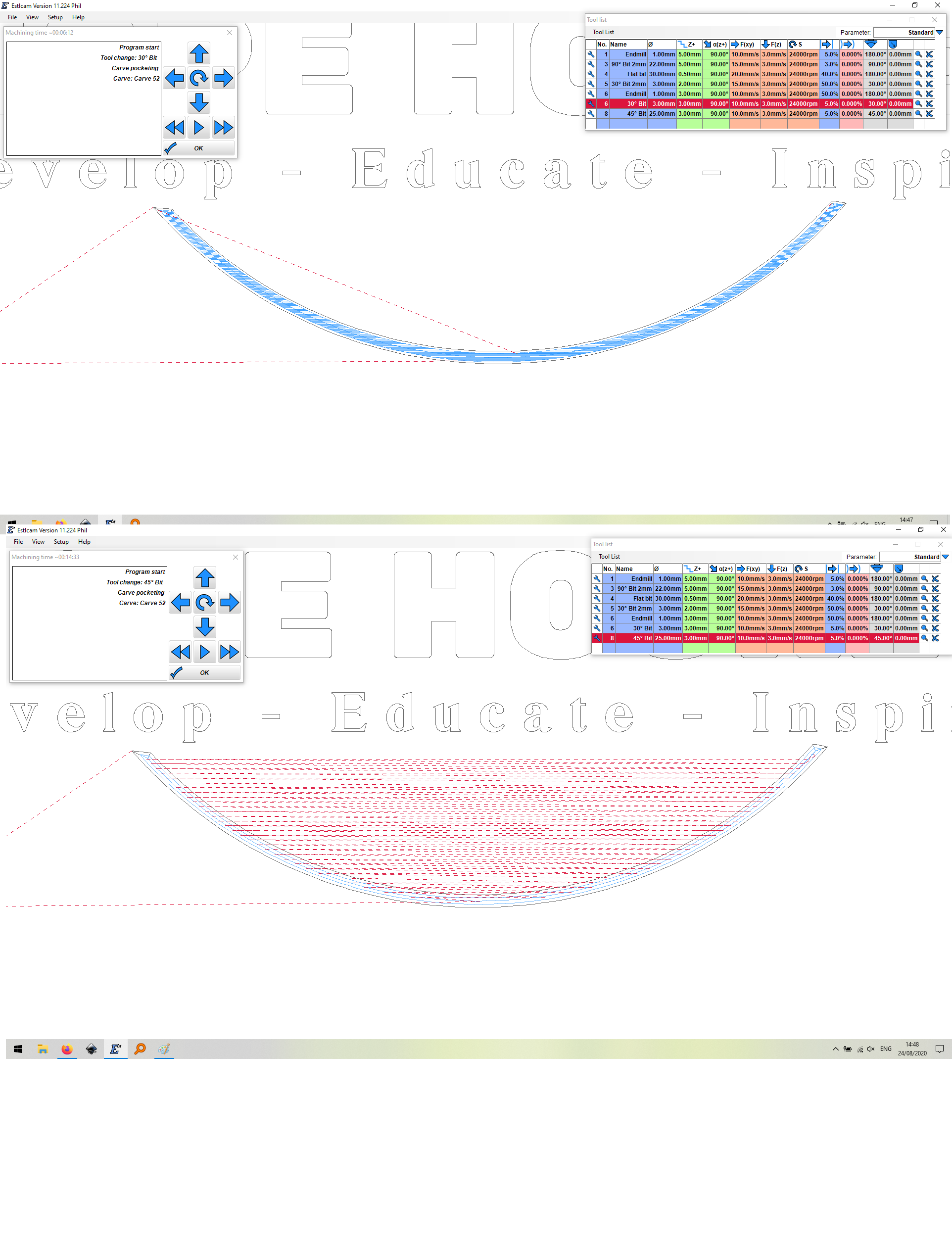
In the first example, the shape is cut out via small sequential adjacent moves within the curve until it’s complete. In the second example, a cut is made, then the focus moves to the other side of the curve, then back, then back again. Look what happens if I remove the rest of the job and just run this part with the only difference being the tool. Perhaps another picture would help…
Now if the explanation is “reread what we just posted”, then I will hang my head in shame and do some thinking. It just seems…odd.
Thanks all for your patience!
Thanks for this Rob, always good to be reminded that there aren’t necessarily simple solutions to apparently simple problems!
I actually find Estlcam to be amazing. For example, I almost always start with “Automatic functions → Create objects automatically”. The “Island” function is also cool. The point is that these are complex functions that save great amount of time. The hidden point is why can’t machining order be this smart?
Altering Machining Order
So it’s worth mentioning the following on how Machining Order is altered. It’s both good and bad. See if this makes sense.
When you click into the Machining order property, it AUTO increments by 10. This is why I leave this step to last. What I end up doing is this loop (not trying to be funny)…
- Click object/toolpath (properties dialog will appear).
- Click Machining Order (it will automatically increment). Do not close properties dialog.
- Click next object/toolpath
- Goto step #2
Machining Order Feature Request
I have not ever made the following feature request but I should. It would be to select a group of objects, and then alter the machining order sequentially. That is essentially automates what I do above.
Yes inefficiency is correctable and I agree the machine order is unfathomable at times but overall I agree Estlcam does a wonderful job and you can correct time wasting movement with a little effort I will have to try your method it looks good thanks
My best guess as to why there is such a disparity in pathing is that for one of the bits, it’s a straight carve operation (the walls of the curve match the angle of the bit), and for the other one, it’s converted into a 3-D surfacing operation, so it does it as a raster, rather than a vector. If you had a bigger 30° bit, it wouldn’t have to do all the back and forth through the curve. But since you have a 3mm 30°, it has to dig down into the curve. If you had a 25mm 30° bit (like your 45° bit), it would likely go much faster.
Well… Now that I’m thinking it through, I’m not sure the 45° bit could carve a 30° profile (it can’t), so do I have that backwards?!? Is it treating the “correct” bit as a 3-D sculpt process, but the smaller bit as a pocketing process? That’s messed up…
How do you have that curve defined?
I should clarify, with respect to my comments. I only do single bit “operations”. So although the multi-tool situation may exacerbate things, I suspect that is probably not the root cause (gut feel).
Regardless of how many bits you use for the whole job, the fact that it generated different toolpaths for different bits is what I was addressing. And why it seemed like one was generating a pocketing job while the other was generating a 3-D carving job.
The image is an SVG derives from an EPS (I don’t know if that matters), and I asked estlcam to 'carve inside. The dramatic size difference between the tools got me thinking that maybe there’s a threshold at which the type of cutting changes, so I explored a bit. If I reduce the size of my putative super tool (from 25 to 15 to 5 mm, it does trigger the change in cutting behaviour:
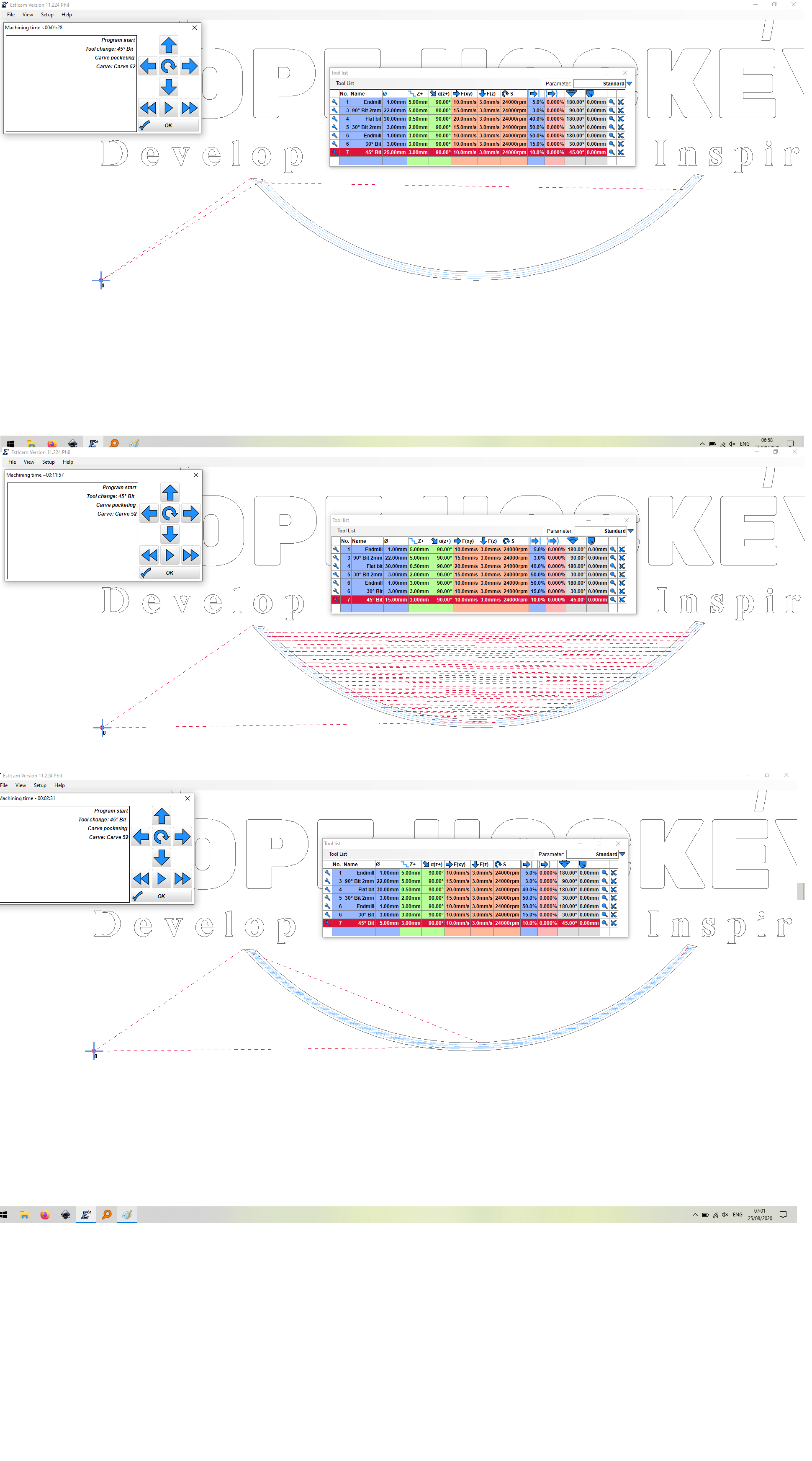
But interestingly it also changes exactly how the curve is cut. I don’t really know how to describe it, but a close examination shows a pseudo-linear approach at 25mm, followed by the same path but cut with a bazillion traverses, followed by a stepwise ‘nibbling’ at 5mm.
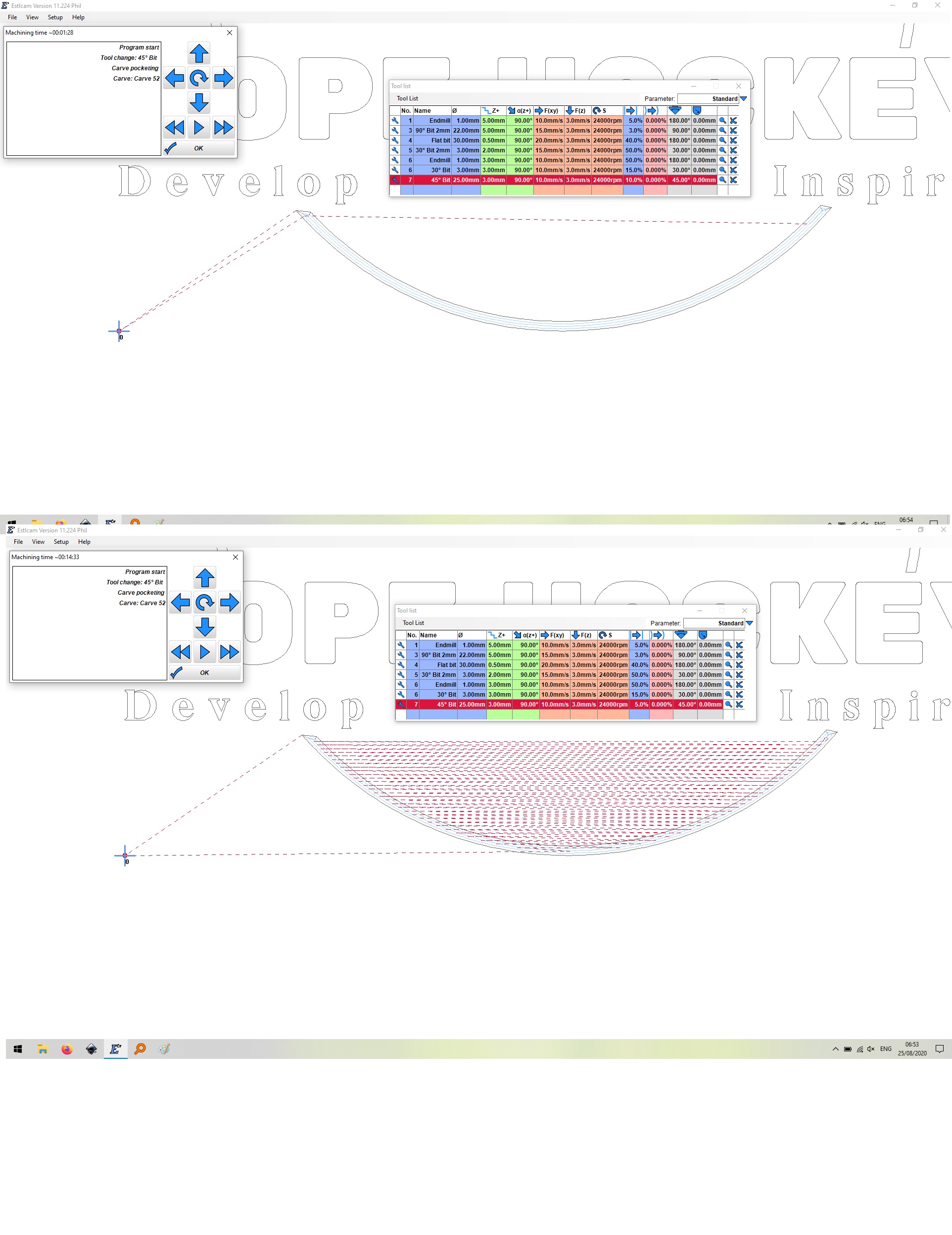
I was also messing with the step over, and this also triggers a change when I go from 5 to 10%:
The thing is, whenever you push any system, you will find areas where there are quirks. As @rwillett points out, this is not a trivial computational task, and I may just be wandering close to an area where things are tricky. I’m not suggesting there’s any problem here, it’s just interesting. Perhaps more importantly though, this has shown me that I should not be lazy. Have a look at the tool path and alter things to try and see if they have any significant effect on the time or cutting approach. Don’t expect estlcam to do absolutely everything for me 
This is another hilarious example of why you should tweak the settings a bit if you end up with what seems an unreasonably long cut time.
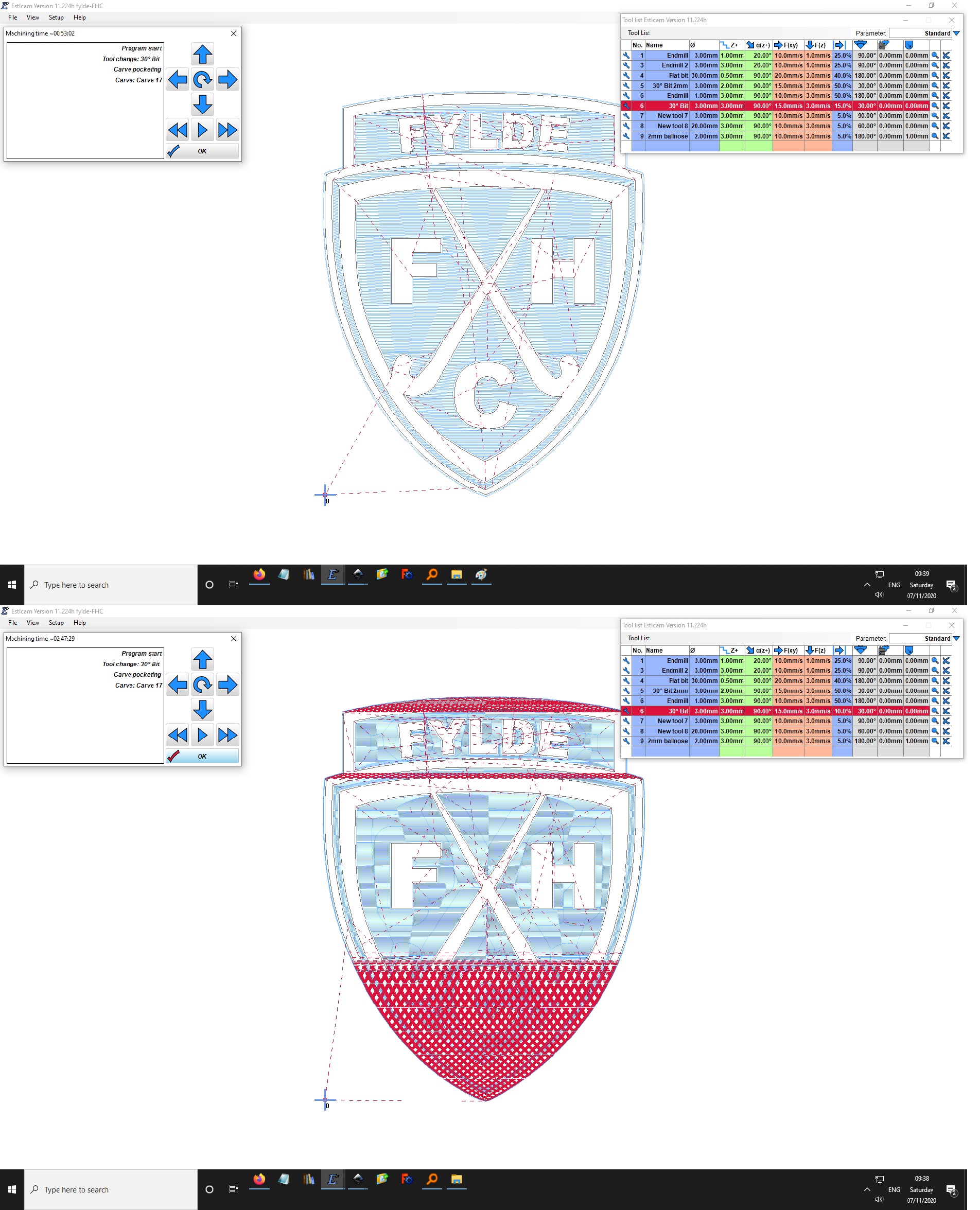
This was a change of stepover from 15 (just under an hour) to 10% (nearer 3 hours).
When working on webcontrol (gcode sender for Maslow CNC) I developed a gcode optimizer based on the TSP. Only trick needed was to set the distance matrix correctly to account for the fact that you are optimizing path order (with different start and stop points) versus travel order. Problem was the ortools library I used (from google) didn’t support raspberry pi so I shelved it. Regardless, when I tested it it didn’t really make any significant improvements to estlcam generated paths. I tend to agree estlcam does a decent job.
Oh definitely, we have discussed the enormous complexity of what we’re asking estlcam to do here, nevertheless, it is always worth tweaking the resulting process as there may be a much more efficient process lying close by.
So I try to think my paths through before I start. I make use of machining order, and typically can just set it to “as selected” but you can also rearrange if you need. The other funky trick you might not have caught is the path starts and stops where you select it on a path. So for example you have 5 holes and then want to finish with a cut out slot, select the holes in the order you want them drilled, then select the path at the nearest place to the last hole to minimize the travel.
I find estlcam to actually do things great once you get that part.
I completely agree. The trap I’ve fallen into is laziness, hoping estlcam will do everything for me without me having to think about it. I feel like I’ve learned this lesson many times over the years!
I did not realize this, thanks for saying it. It seems sort of obvious now that I know this but this will change how I do things for sure.
Just a little effort has solved my original problem…
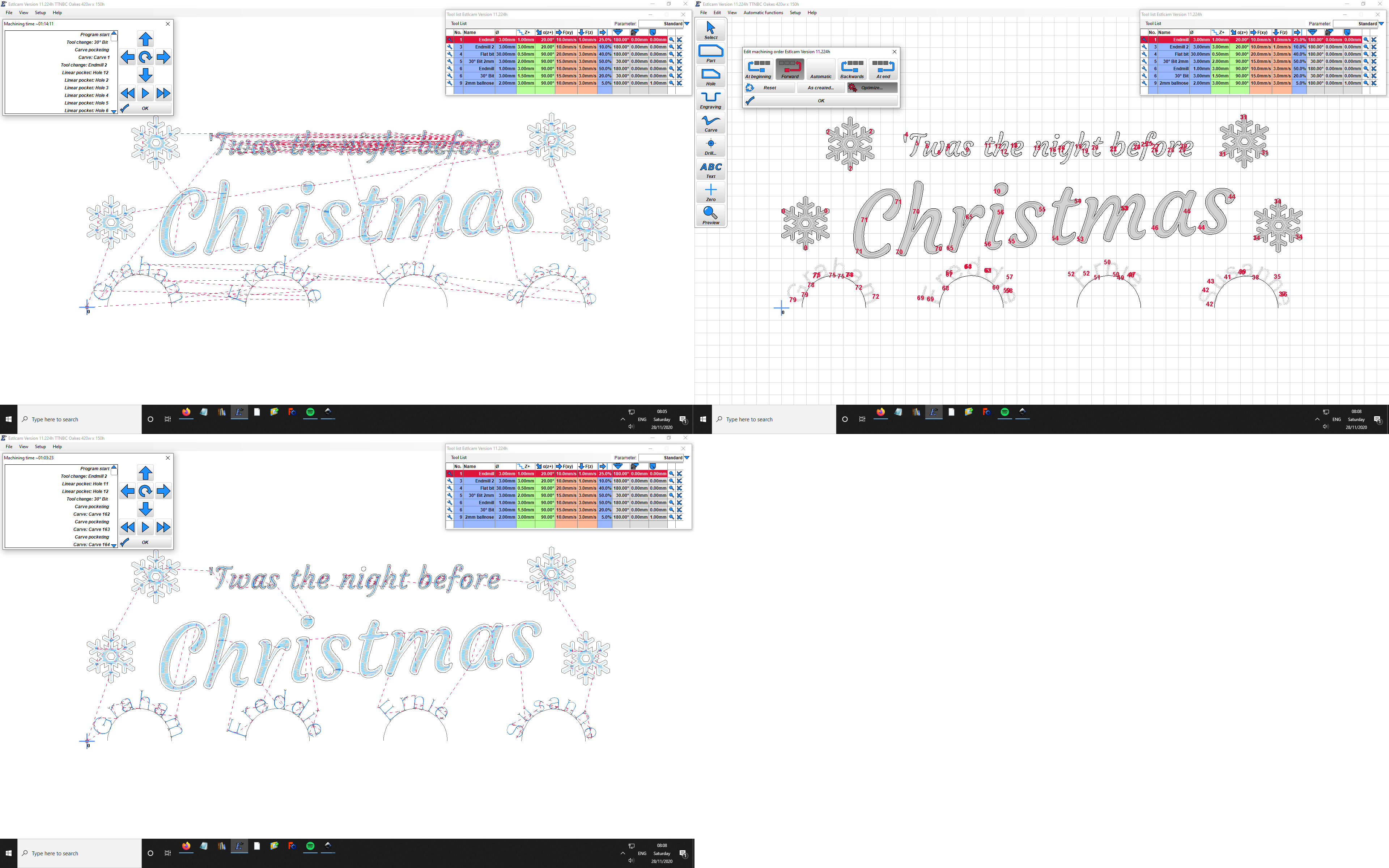
I hadn’t looked at the ‘edit machining order’ window, because I didn’t know it was there. However, there’s an ‘optimise’ button! Hit it and all the nonsense goes away. I feel like I owe estlcam an apology. Curiously, if I then hit the ‘As created…’ button, it doesn’t revert to the silliness. Anyway, problem solved with minimal effort.