Doing it the hard way

Probably the wrong place for this (Admins, please move to the correct place, if needed!), but, here I go.

Because I enjoy learning new programming systems (yes, I’m probably a little self-abusive! :slight_smile: ), and because I always have problems translating my ideas into useable code via the applications that I’ve tried so far, I decided to try to simplify some of it.

Most recently, it’s making oval/eliptical cuts. So, I worked out an Excel 13 spreadsheet to create the G-Code for me. I’m attaching it here (in a Zip format), in case anybody else wants to look at and/or use it.

The only 4 items that you need to change to generate your code are the X and Y center point coordinates, and the X and Y radius dimensions. (Remembering - like I didn’t, a couple of times - that these are radius and not diameter dimentions.) Your X and Y center point coordinates MUST be equal to or greater than the X and Y radius dimensions.

After you’re satisfied with what it will look like, you can copy and paste the G-Code into your own file using any decent text editor. Personal preference for me if Notepad++, but that’s just me. Please do remember to put a statement in after the first line to drop the tip of the cutter bit the necessary depth for your cut.

I’m using a MPCNC, and it works fine on it.

If it’s not fine enough in movement (which may occur if the overall dimensions get too big), please feel free to let me know. It is currently set up for 1-degree steps, but could easily be modified for 0.5-degree, 0.25-degree or 0.10-degree steps to smooth out your cuts. (Keep in mind that the higher the resilution - the smaller the steps - the more lines of G-Code you’ll have to copy and paste.)

If you have the need, you should be able to copy and paste only what you need for an eliptical arc, too.

Thanks,
David

PS: A parabolic arc will be next. Yep, I’m a glutton for punishment… :slight_smile:

Ellipse - Oval Coordinates.zip (57.7 KB)
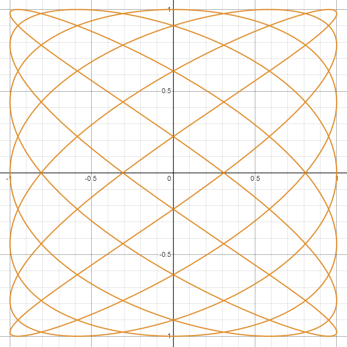
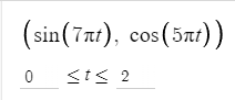
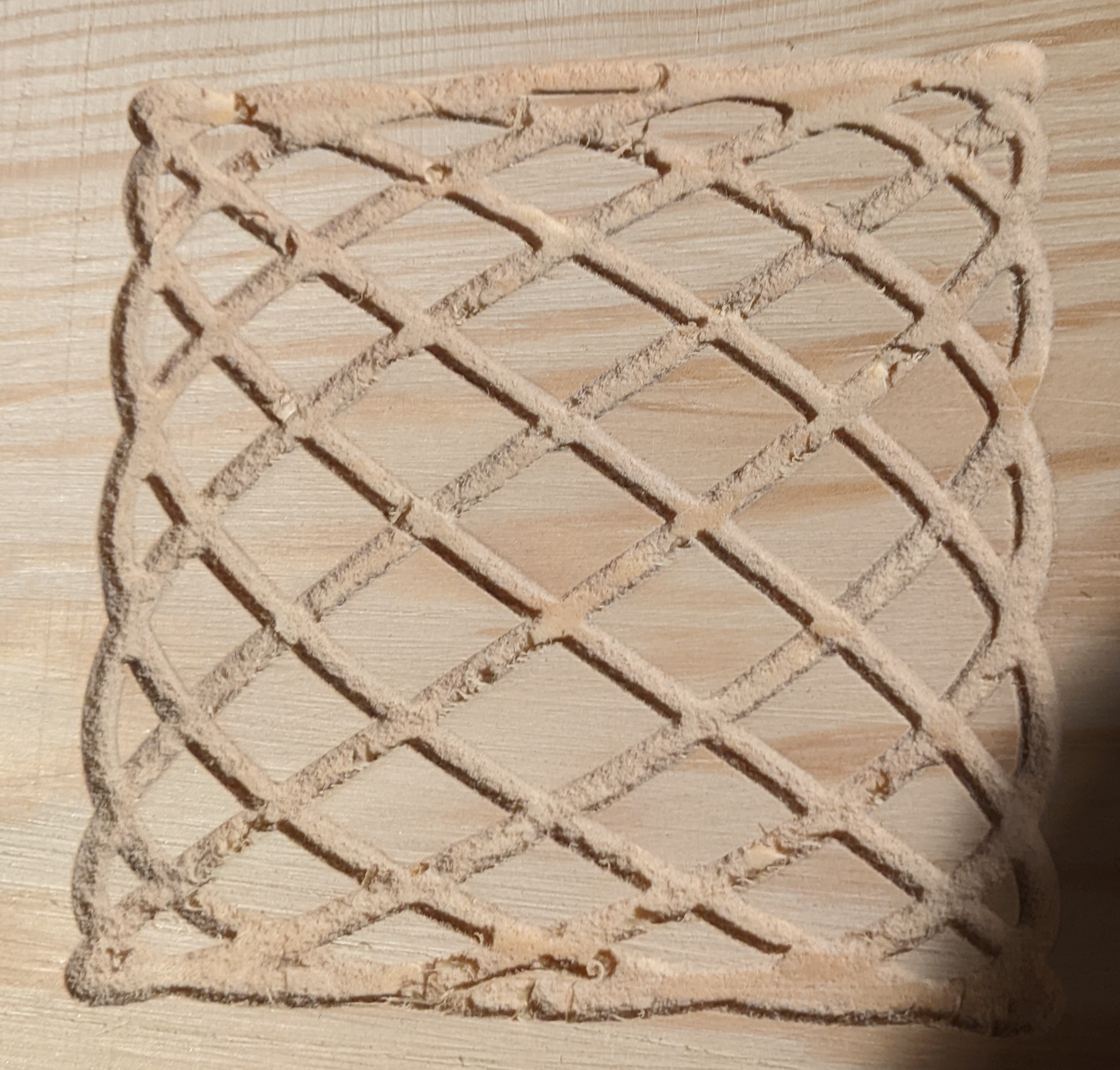
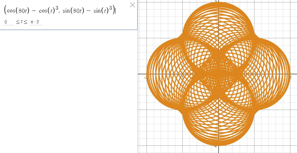
4 Likes

It would be interesting to do more complex parametric equations that cannot be done with CAD packages. For example:


image

This is the same framework as your ellipse. There are a bunch of parametric equations on the net as starting points, and there are also online graphers, so you could play with the equation quickly until you found something you wanted to move into Excel.

Edit: The equations that emulate a SpiroGraph are a rich source for interesting paths. Here is another page.

3 Likes

Awesome… I love the idea of creating spirograph art on a cnc! I imagine some really cool looking marquetry using assorted species in a spirograph layout… intriguing.

Thank you for the links! I think that they may translate into some interesting graphics for engraving. With a little added “finesse”, this may also translate into something similar to Celtic knots.

Fortunately, in some respects, I’m single and retired. However, my cat may not be happy with you pointing me in the direction of another temporary obsession… :wink: :rofl:

2 Likes

If you like this kind of engraving, you might take a look at Jeffeb3’s Sandify. Its target is sand tables, but he allows the files to be saved as SVGs, so they could be laser engraved or carved with a router.

1 Like

Hmmm. I tried just running the generated Gcode on my laser, which works, but the acceleration values on my laser seem to muck up stuff, because I get small gaps in the laser passes where the acceleration happens, and the laser duty cycle falls below what is adequate to actually engrave. The answer (I think) is going to be to increase the acceleration on my laser to make these gaps smaller. I’ll have to see how fast I can get the laser up to full speed in order to remove those gaps.

1 Like

Are you driving your laser with inline commands or with fan g-code? There were some forum posts with laser quality issues similar to what you are outlining. The problems went away when the OP moved from fan codes to inline commands. I always assumed that the Marlin laser code scales the power based on speed/acceleration. I read one post by I think Ryan that said the Marlin laser code had (again?) been rewritten and would be rolled into a V1 build after it had been tested. If this is true, and you are already using inline commands, it might be worth getting a V1 nightly build to test.

Edit: Rereading your post, it actually the scaling that Marlin does causing the problem. Not sure if the min power output in LightBurn will address this or not.

1 Like

Sandify doesn’t do anything but the G1 commands. You need to add some starting commands to set the laser power.

If there is any adjustment to the min laser, you would have to do it in the firmware. But I think Dan uses duet firmware. Raising some min laser power would probably help.

You can use the gcode directly, but with some smart starting gcode to raise the bit, move to the start, sink the bit and set the speed, then raise the bit. IIRC, there are some examples in the sandify wiki.

In my case, I’m using GRBL on an ESP32, because I’m using one of Bart Dring’s TMC2209 pen/laser boards. I set the travel rate and the laser power as a part of the setup code in Sandify, as well as defining the area that I wanted to cover.

I don’t think that the min power in Lightburn will change anything for me, can’t really say for the SVG output, since I’m not using it that way, but I am confident that I can get good results this way, so long as I tweak my tranvel and acceleration values appropriately.

2 Likes

Square Spirograph.zip (176.7 KB)
Well, there you went and done it! :smile: I couldn’t resist!

From your example, I submit a rough test cut, and a spreadsheet.
In the spreadsheet, change the X and Y variables for changes in the graphic, the Scale variable for actual cut size (this one is set up for approx 4" x 4"), and the Offset variable to move the bottom left corner up and right from the origin.

I had a 4MM bit easily at hand when I went to test this. When I cut it again (and, I plan to), I’ll use a smaller bit (probably 2MM or so) to get better resolution. It’s either that or cut the overall size much bigger, which I don’t want to do, at the moment and for what I have in mind.

4 Likes

Very cool. Try cutting it with a chamfer bit. It might make an interesting edge-lit, acrylic sign.

1 Like

Years ago I played with parametric equations as part of an “art” project. Some of the equations yielded intricate, and to me, beautiful graphs. I poked around a bit on the net yesterday and found the following five on Wikipedia:


The lines for these specific equations are likely too fine for a router, but pen, laser, or drag bit would work. I found a number of other graphs that I liked, but the equations were substantially more complex, and I’m not sure of the limits on Excel’s math handling.

3 Likes