My motor cabling is end-to-end i.e. 4 wires from each motor to the board. Is there anything I need to change there?
Now quoting the dual end stop instructions, and again please excuse my ignorance…
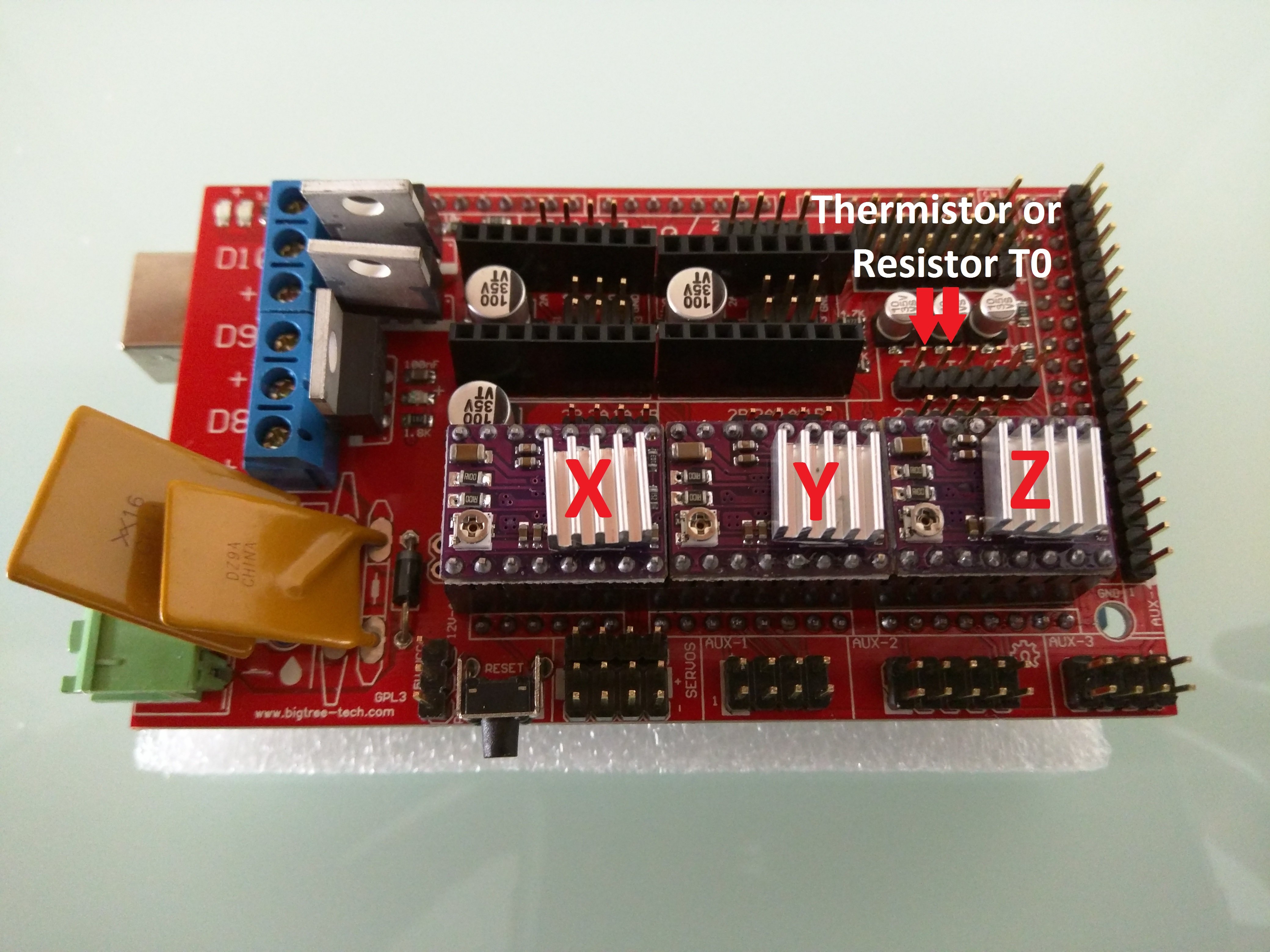
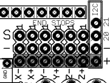
The min pins are used as normal for the first stepper and the max pins are used for the second stepper on that axis (X2, Y2, Z2), still as a min. For example, X1 pairs with Xmin, X2 pairs with Xmax. DO NOT USE THE + (positive) Terminal. S & – (signal and Negative) Only Xmin=X1 limit switch Xmax=X2 limit switch Ymin=Y1 limit Switch Ymax=Y2 Limit switch Zmin=Touch probe. Signal pin to plate, negative to tool. For the safest configuration the endstops should be wired in the Normally Closed position (NC), to prevent wire disconnects from damaging the machine during the homing sequence.
I should not connect anything to the pins in the blue square
(–) goes to common and S goes to NC or vice versa?
starting from top we have Xmin, Xmax, Ymin, Ymax and Zmin, Zmax? That leaves the 5th and the 7th pins unwired, correct?
For Z I see some people using an endstop switch also instead of a probe.
a. Is it possible by the firmware to only use X-Y end stops for start and place the Z axis manually?
b. When we say probe we mean something like this? Amazon.com
I do not have a ramps board but I will answer the questions that I can.
Yes.
If you have 4 wires from each motor to the board than you shouldn’t need to change that. You do need to make sure that you isolate each stepper (right now you should have wires that connect directly from x1 stepper to the x2 stepper in a series configuration and same for y). Meaning each of the 4 wires from each stepper now will connect to the board rather than some to the board and some to each other.
Correct
This depends, I think the firmware is set up for them to be normal open (as that is the default so that you can use duel endstop wiring without the endstips). So unless you changed it, you would want to wire them to the NO and common pin. Also convention says S would go to common and NO would go to - but it doesn’t really matter as it will work either way (like how convention says red wires are + dc voltage but nothing is stopping you from using a red wire as a ground).
Yes
While that would work, generaly we are referring to touch plate probes like this:
The firmware is setup for normally closed. This is the safer method of wiring since a broken or disconnected wire results in no movement during homing rather than slamming the switches into the stops. As Atom says, polarity does not matter.
I should not connect anything to the pins in the blue square
Connecting in the blue squre == bad things happening like burned out pins or a blow voltage regulator, or blowing a hardwired fuse.
Is it possible by the firmware to only use X-Y end stops for start and place the Z axis manually?
Homing can be done in different places and different methods. All methods that I’m aware of allow Z to be independently homed from X and/or Y.
Thank you for your replies! You helped me a lot with some important questions I had. Can anyone answer question #3 pls? [quote=“Christos, post:1, topic:27138”]
starting from top we have Xmin, Xmax, Ymin, Ymax and Zmin, Zmax? That leaves the 5th and the 7th pins unwired, correct?
[/quote]
I suppose I can do some trial and error but if anyone who has this board and uses end stops can assist it would be “safer”.
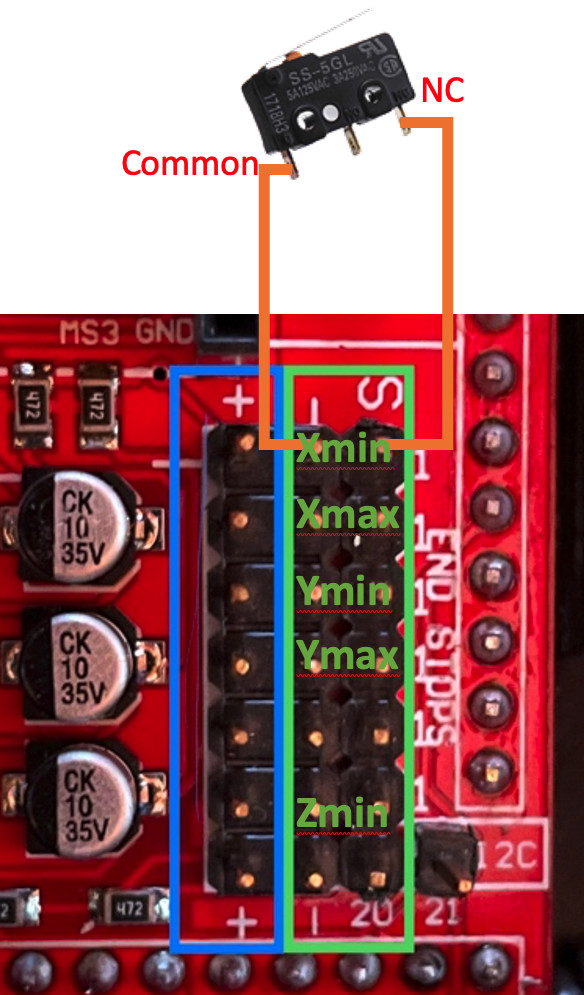
I don’t have a ramps board, but I believe you have a problem with your Z wiring. You want Z min. Here is the Ramps 1.4 pinout for the endstops:
So according to the documentation, you want the Z touch plate to be plugged into Z min (Z-), so the 6th and 7th would be unwired, and Z touch plate would be wired to the 5th.
No, for 2 position switches, you do not need +5V. Those are for active switches, optical endstops and the like.
By convention, I wire S to Common, and Ground to NC. This is because in the case of using 3 wire switches where the switch would change the signal between high and low it is the common pin that would carry signal. But for this application, it doesn’t actually matter.
Xmin goes to the switch nearest the motor connected to X, Xmax goes near the motor connected to E0, Ymin goes near Y, Ymax goes near E1, Zmin goes to the touch plate. Do not use Zmax and the I2C connector is something else entirely. I was actually pretty sure that the Zmin was the one above there, next to Ymax, not the one that you have indicated.
Becasue you’re dealing with a variable length tool, a mounted stop switch for Z isn’t going to work well. A touch plate is basically being used as a switch and gives us the position of the tool in the router.
The Z min is set up for normally open to be used with a touch probe (and Robert is right on the rest, they are normally closed)
I’m not sure how you are counting where you ended up with 7th, The 5th and 6th (both labelled Z) are not used if you don’t have a touch plate.
After you think you have it right, check the endstop status with M119. This will help you find out if you wired something to the wrong port (pay special attention that X1 matches X1_min, etc).
Now I see what you mean. You’re right I counted the last row of 4 pins in Ramps board as end stop pins but seeing it again after your comment I understand they serve a different purpose so the end stop pins are 6 rows not 7.
Can I ask why is this so important? My understanding is that both max and min serve the exact same purpose in this setup; what is the Robles if any end stop of x axis for example, is matched to any of the two motors of that axis?
Motor X1 must be matched to endstop x-min, and motor X2 must be matched to x-max. In homing, the motors are driven independently, so the X1 motor will stop when the endstop on that end is triggered. This allow the two ends to square themselves against the endstops. This is the primary benefit of endstops. Once you get your rig setup, you can test this by moving an axis out of square and then running the homing sequence. You will see one motor stop before the other.
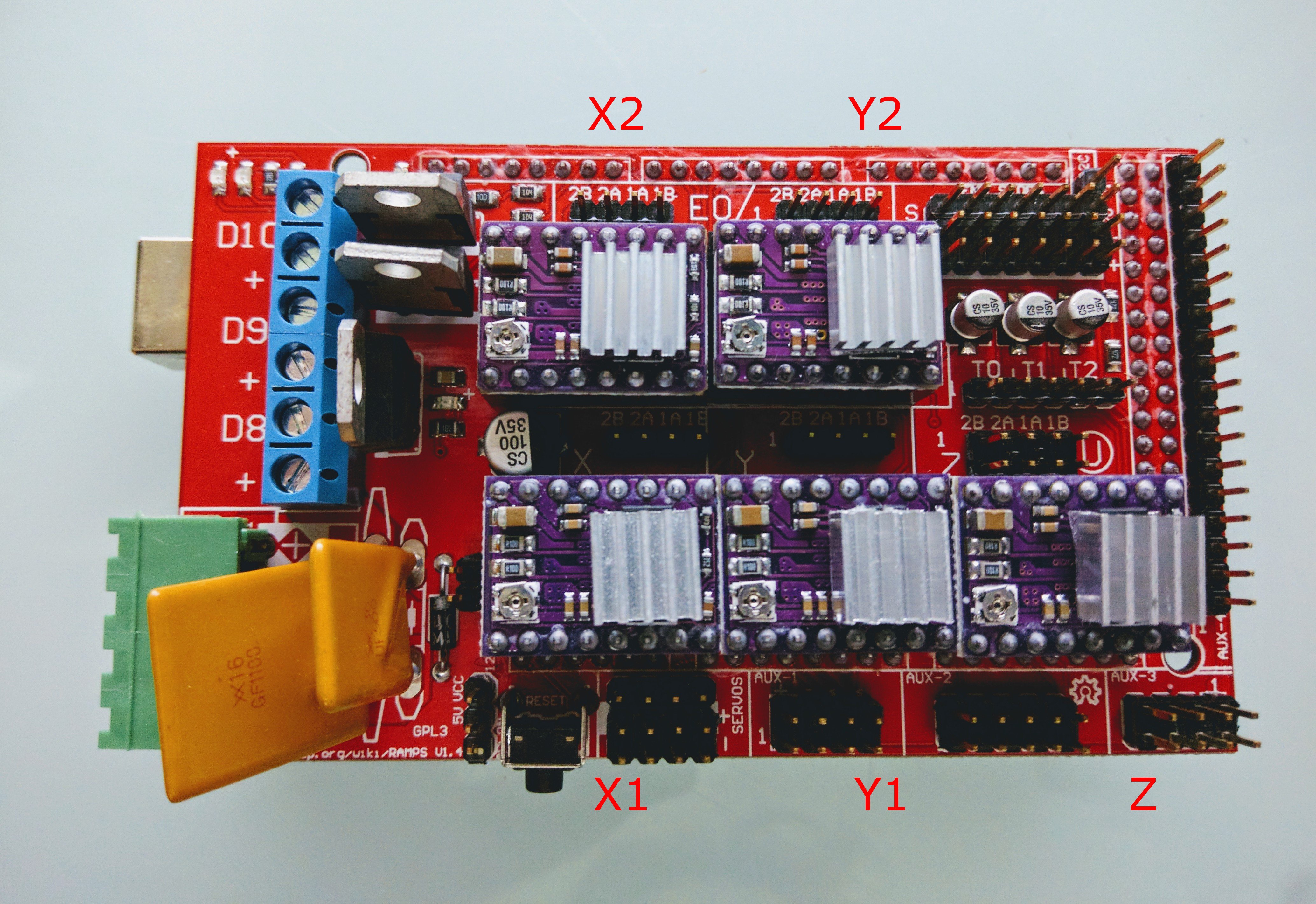
So for dual endstops, you use 5 drivers for 5 motors. On a RAMPS type board, these are typically labelled X, Y, Z, E0, E1. For purposes of 3D printing, they are for the X, Y and Z axes, as well as 2 extruders, (E0 and E1)
The V1 MPCNC firmware for these renumbers them, and they are instead used as X1, Y1, Z, X2, Y2, but X2 and Y2 will still be laballed as E0 and E1 on the actual board.
Thank you all, i’m a lot more confident to power up the board after your help and clarifications. One last question, I see the point of having the X1, X2 etc paired in a specific way, but… does it matter if in my setup X1 or Y1 is the left or the right motor of that axis? I guess that as long as it goes to the correct end stop i.e. the end stop on the same truck as the motor and the pairing is according to what @robertbu said, motor placement shouldn’t matter, am i right?
That is correct. As long as the endstop is matched with the motor, it doesn’t matter which is which side.
For ease of troubleshooting, I set mine up so that X1 and Y1 are the motors on nearest the origin of the machine, that is to say that the X1 motor lives on the rail closest to minimum Y and the Y1 motor lives on the rail closest to minimum X
It will matter if you adjust the squareness with software. M666 will let you add an offset, so one motor will jump away from the endstop a bit more after homing. It is useful if your physical endstops aren’t perfectly aligned with square. But if you do M666 X0.5 and that moves it the wrong way, you can do M666 X-0.5. So not a huge problem.
Everything seems to work just fine! I performed all the checks mentioned In dual end stop section and they pass, so once more thank you for your help!
One thing I noticed though is that with the new firmware, after homing, I cannot move either X or Y pass 200. Before homing I can take them all the way to the other end but once I home X and Y, 200 seems to be my limit. Any idea why?
Also is there a way that I can “hardcode” my firmware so that it homes after every reboot automatically and it also knows the max distance it can travel on X and Y after homing?
If you are limited to 200, then you don’t have the latest firmware installed. The latest firmware sets the limit at 600 instead. The two lines in configuration.h that set this limit are:
// The size of the print bed
#define X_BED_SIZE 600
#define Y_BED_SIZE 600
Unfortunately thse values cannot be set by g-code and would need to be modified in configuration.h to match your working size and Marlin recompiled and reflashed.