Am looking to do a better job (for me) on making a dust shoe than the options I have seen to date. All suffer from a few issues and don’t work for me.
My issues with the 3-4 I have downloaded and tried is:
They don’t seem to fit very well.
They are big and interfere with clamps holding the material down.
They seem to stop me easily using the Z Probe (my newest and most favourite toy for this week).
Some attach to the wrong part of the Z axis putting load and torque on the wrong part of the system. I do read Ryans advice
Changing tools is a nightmare.
I want to have a proper look at these and to try and see if there is a better solution. I’m not taking my working CNC to pieces yet again, so I thought I’d print one out and then I have something I can hold in my hand and see what thought processes it stimulates.
I don’t need 55% infill, could I get away with 10%, what suggestions would you have to print it as fast as possible as it will be used just for modelling purposes. I’ll also print a model Makita router, tool board and other bits so I can check clearances. As my MPCNC is built, the Ender 3 Pro is sitting idle and feeling unloved as all my attention is on the MPCNC, yes I am fickle.
PrusaSlicer quotes 19 hours for two pieces with zero infill and 26 hours with 10%. I’ll go with the 10% just to make sure, I’d gate to drop it and deform it.That has amused me though.
I’m in the same place. Want to start looking at hooking the vacuum back up, but need to figure out how to mount something and route it around the Z-Axis. I printed out the first 6mm of the Core so that I had the hold placement and could see where the Z-Axis rails run. I’ll use that as I try to visualize how everything should layout.
I’m doing the whole lot again but at 10% so it has some rigidity. I want to look at running an exhaust down the back or sides or wherever. Thats why I want the whole lot. I’ll put a couple of spare tubes on and see how it moves up and down and where it’ll hit. CAD (Cardboard Aided Modelling) may come into it’s own.
I have spent hours looking at my MPCNC Z gantry trying to work out how to move things around. My brain isn’t good enough to visualise it, so I’ll make the lightest, flimsiest gantry I can and cut bits of cardboard out to see what can fit.
My requirements are:
Works with a Katsu router. This has issues as it appears to blow air down onto the collet as opposed to the DeWalt which doesn’t. This interferes with the exhaust system. This is probably the same on a Makita.
As small, light and thin as possible so that bumping into clamps is reduced (or removed).
Allow access for the Z probe to be used. This is my favourite toy of the week.
Possible allow access for a endoscope type camera so that I can see marks for setups and stuff like that. Not a major requirement but more a nice to have. They are also cheap at around £8-£10 here in the UK. $9-$11. Not even worth going to Bangbang.
Fixes to the gantry rather than the moving Z axis. Very important to remove torque on this component.
Works with a Henry hose (very popular in the UK). See also Henrietta. Needs to adapt to other hoses though as I might change our vac.
Need to think about how ‘brushes’ or similar are used. e.g. I can print them, but wasn’t that happy with them, decent hair brushes would be great and would reduce dust.
I’ll change the title on this thread and use it as a log for work and if anybody wants to chip in, please do so.
Have now started seriously thinking about a better design and have a few ideas that meet the criteria. The main problem is still how to mount it to the gantry and not to the Z axis BUT allow it to be adaptable to meet the work surface.
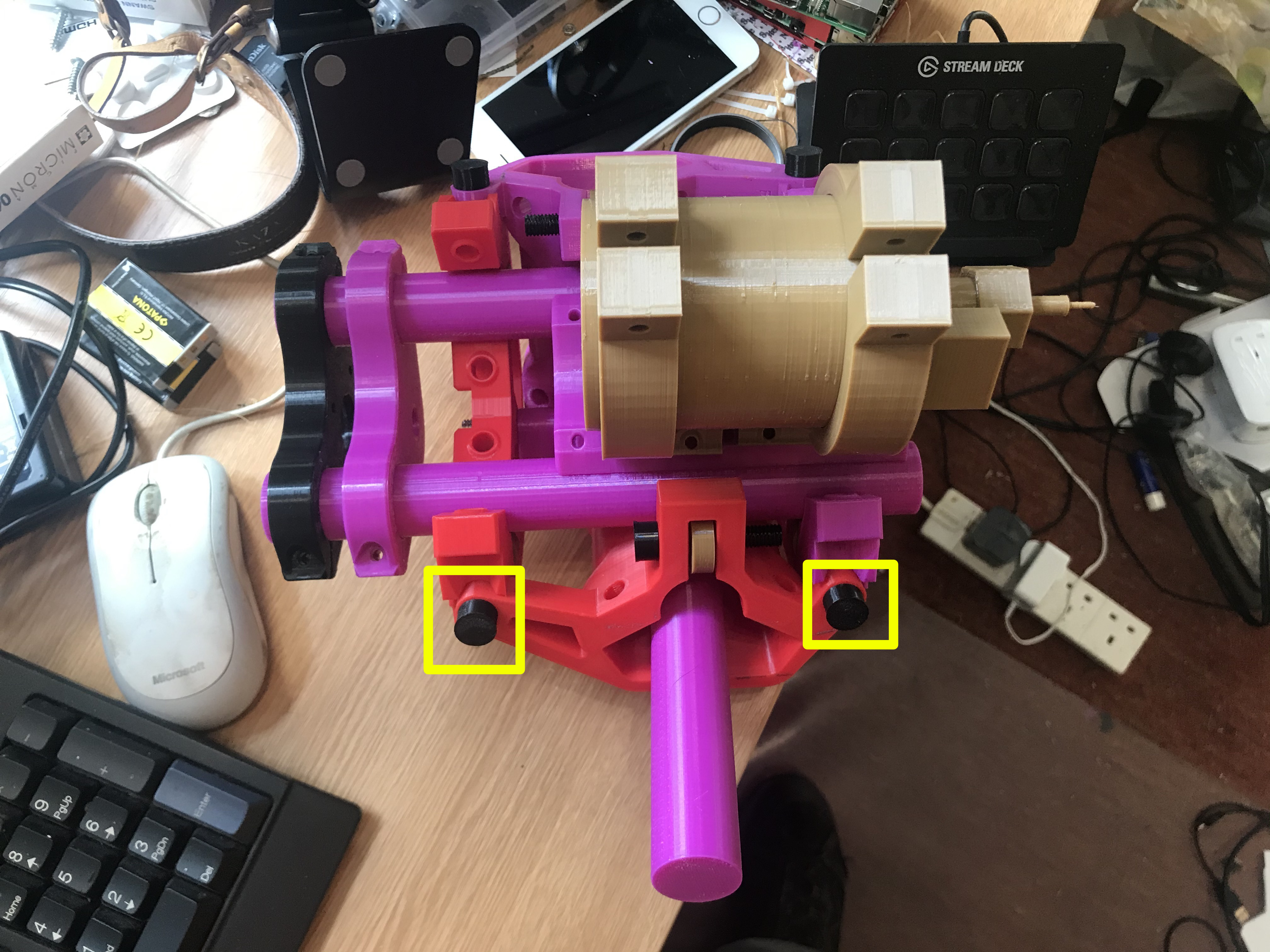
I’ve mostly printed out a dummy Z axis with as little infill as possible to look at the spacing and dimensions. It’s actually quite robust and works quite well with pretend bearings and printed bolts. You may note the weird and wonderful colour scheme of filament I don’t particularly like.
Anyway, I wondered if there was any reason I can’t attach things to the bolts highlighted by the yellow squares. This would be lightweight (< 150g I think), but compared to the weight of the Katzu router, negligible. I am still knocking the ideas around in my head, but this is the most pressing element that needs deciding until the next one. I can’t see it being an issue, so any advice welcomed.
This dust shoe on Thingiverse uses those bolts: https://www.thingiverse.com/thing:4166046. I also liked his idea of a square tube that fits behind the core and does not take up any of the X and Y space. I borrowed his idea for my (functional but still prototype) dust shoe for my Primo.
That might be useful and save me some time. I can mount the hose using that. Thanks for that.
The main effort is the dust shoe and I can imagine what it might look like. I’ll spend some time tomorrow skating ideas and use CAD (Cardboard Aided Design) to see how it looks.
Here’s the first thoughts and actual layout for the dust shoe. I will now pretend that I have a fully thought through design and plan and all I am now doing is merely executing the steps that are laid out on a project plan. Any comments otherwise are heresy
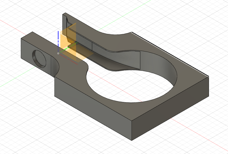
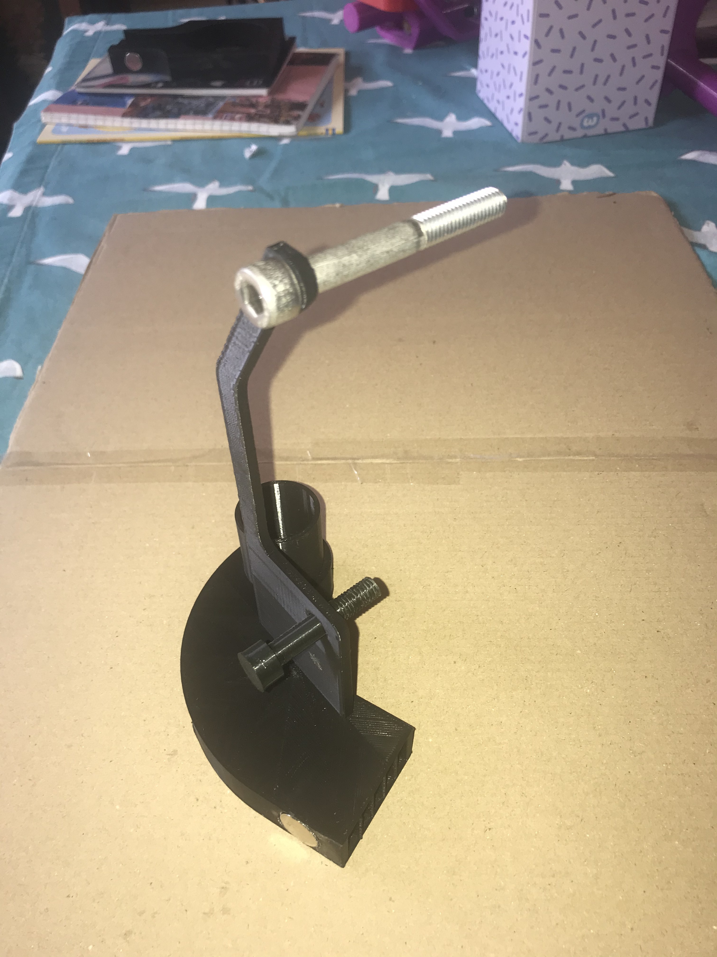
As I am using CAD, the first thing I need is this:
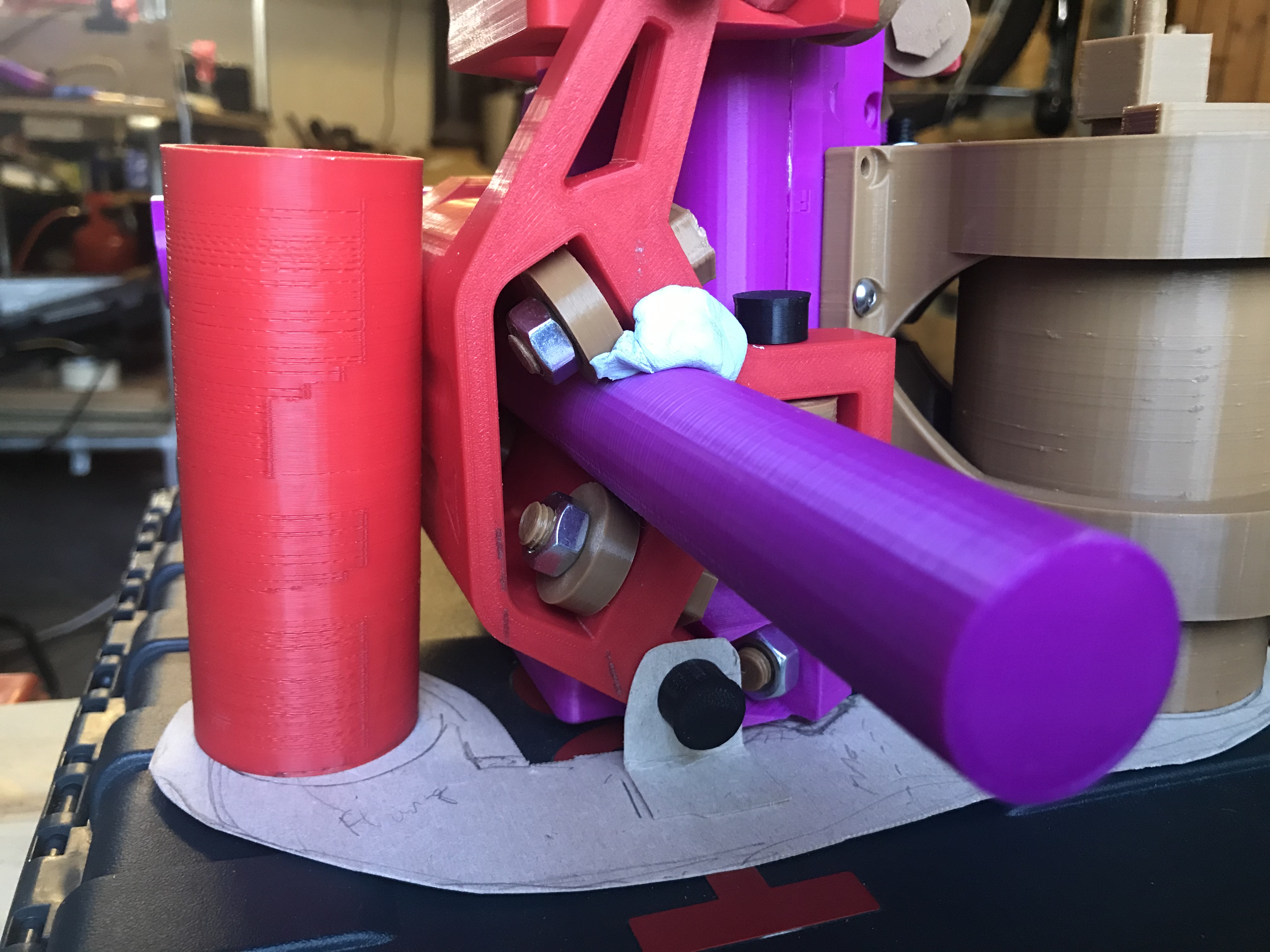
My intention is to mount the dust shoe using the bottom mount on the Z axis at the yellow square. You can see the card flange I’m using to work out the sizes. There’s nowhere else to mount it on this side (so far).
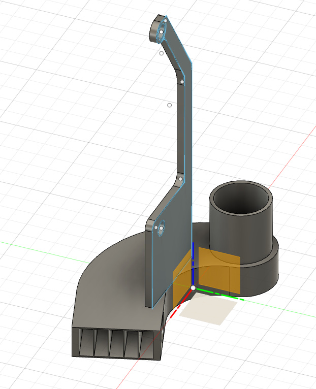
This is the far end of the dust show. This is where we will suck the bits through. The red pipe is just to give me an idea of how to connect. It’s likely that I will use the mount hole in the blue square to hold the pipe which will be connected via flange.
I’m making the hole for the Katsu router large as the Katsu exhausts air down around the actual spindle to I’m hoping (ahem), that the dust will be pushed down and then along the body of the dust show to the red pipe. I’ll put in some simple deflection valves to aid the air flow and if I narrow the dust shoe body, I may be able to accelerate the air and pull the dust along through the venturi effect, something similar to F1 cars. The intention is not to have a top cap on it at the moment. Lets see how that goes.
This means that all the dust shoe is supported on the gantry.
I guessing that the cardboard represents a plate that will be fixed on the core and the skirt will descend from there and reach the waste board. If so, your contour around the router is pretty close given the working height I see on your MPCNC in the background. There is good chance that eventually your skirt will be deflected by your material or by a clamp and either be cut by the bit or wrap around the bit and be yanked free. I’ve seen this problem solved in two ways in other designs. Some just make a much bigger plate around router, but this creates a larger area to “depressurize.” The second way is to make the plate movable with a shorter skirt, and you lower the plate so that the skirt touches the top of the work piece.
You are correct in what you say regarding height. However there are a number of things I will also do to hopefully avoid a number of potential issues.
I will increase the height of the MPCNC legs. I got the height wrong at the design stage. My intention is not to cut/carve wood so this shouldn’t be a problem. Ryan thinks it’s OK. I have a 1m stainless steel pipe waiting to be cut up. One of the reasons for the steel piping above the MPCNC is so I can suspend the MPCNC from the pipes whilst I replace the legs. The reason I haven’t done this is I need to complete some engraving work the CFO committed me to for free.
The dust shoe itself will be variable heights. I am looking to create different heights of dust shoe that connect to the top plate using magnets. This allows me to easily and quickly change the height by simply slotting a different wall on. Not sure if it will work but let’s try. Magnets ordered.
Your point on depressurisation is valid. I need to keep it tight to avoid significant air leaks and to give the air skirt space to work and not get caught up in spindle. As I have found it impossible to get what I consider the right skirt material, I have had to compromise and use a 12mm door skirt. This is shorter than would like and has forcede to look at the modular approach to the dust shoe height.
A different option would be to make the red tube at the back of the core slidable by putting it into a second larger or smaller tube. I would then have to make the second mounting point (yellow square) also height adjustable. Easy theory but not so easy in practice given my limited skills.
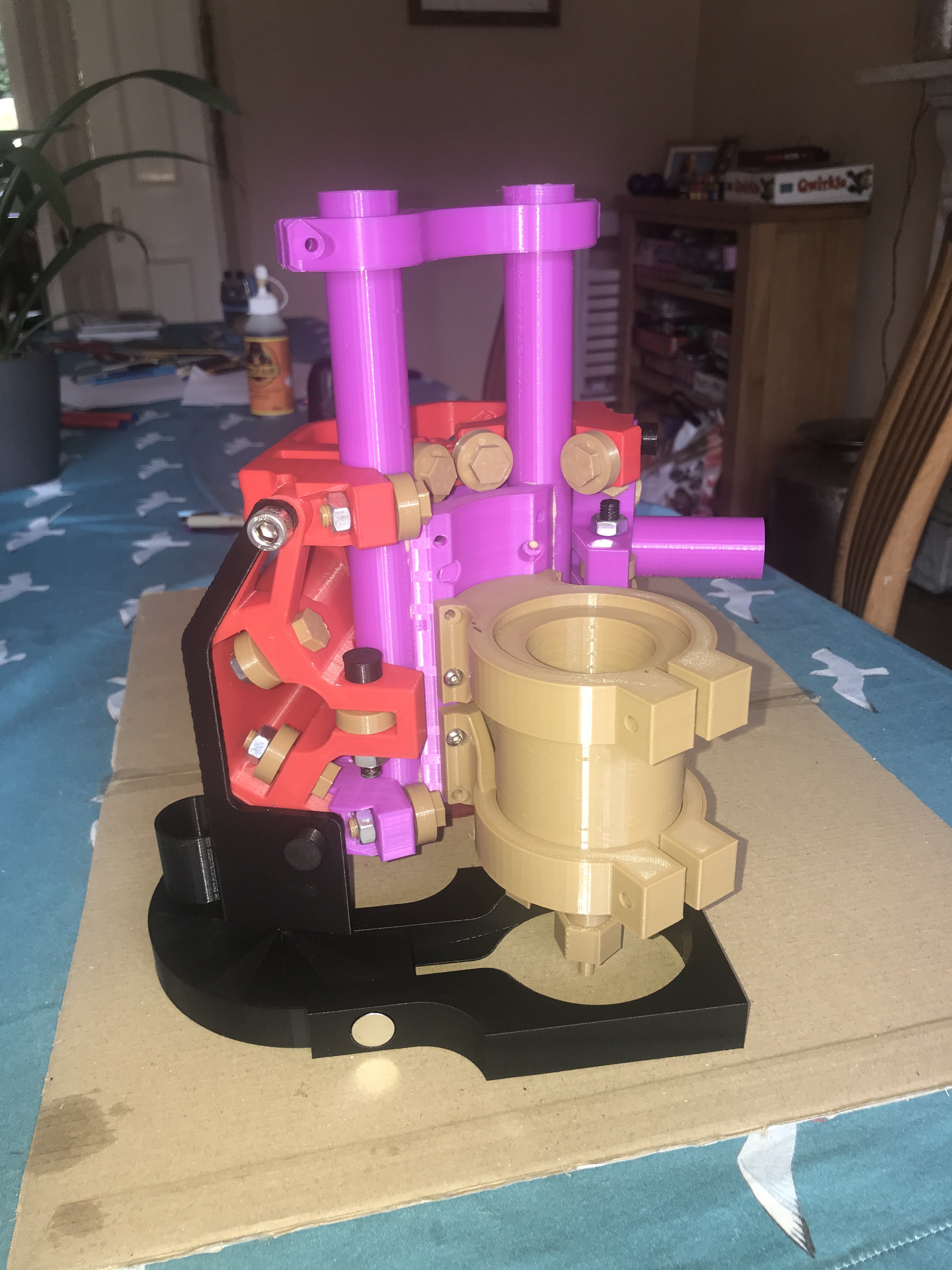
I now have a working prototype that fits most of my objectives I set out in advance.
The dust extractor system is modular and connects to the Z Axis core (not the gantry).
It allows different head adaptors to be easily designed and added.
It allows different work heights using different height head adaptors.
It allows the Z probe to be used easily as the head adaptor can simply be pulled off and changed in secs.
It connects to the core Z movement, not the gantry, so the hose doesn’t introduce torque (or at least a lever effect).
Works with a Katsu/Makita router which is wider than a dedicated CNC router. It can actually fit any router though (within reason).
It works with a 40mm OD/32mm ID hose. This hose routes around the back of the gantry and doesn’t take any space up. This is the size of the Henry vacs which are popular in the UK.
It uses 16mm magnets to hold the head adaptor to the base. These are cheap and powerful.
You can see the hose attachment at the back. This doesn’t reduce the working area of the CNC which is nice.
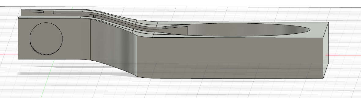
There is also another head adaptor that drops the height down by 7.5mm if you have a lower work height. My intention is to have different heads for different work heights. Also the hole in the adaptor is for a Katsu/Makita sized router, it would be trivial to make a smaller hole. I haven’t printed this yet, but it’s about 30 mins work to design different height sizes from the main Fusion 360 design. I’m doing a 12.5mm one as well.
I need to test the brushes I have to see how much I can get away with in height variation, but at the cost of 46.04g of filament (approx $1) plus two magnets, plus some brush material, it’s no big deal to have a wide range of them, especially as they take seconds to change.
All pieces are printed in one go, so no joining anything together (magnets excepted), and no supports needed on my Ender 3 Pro.
The next job is how to work out how to attach the base plates to the Z axis easily without having to dismantle it all. Mmmm.,…
Somewhat surprisingly it actually fits together. The magnets hold the front very neatly and firmly but I can change the height adaptors in seconds. I’ve now made height adaptors for every height from 0mm to 15mm at 2.5mm intervals.
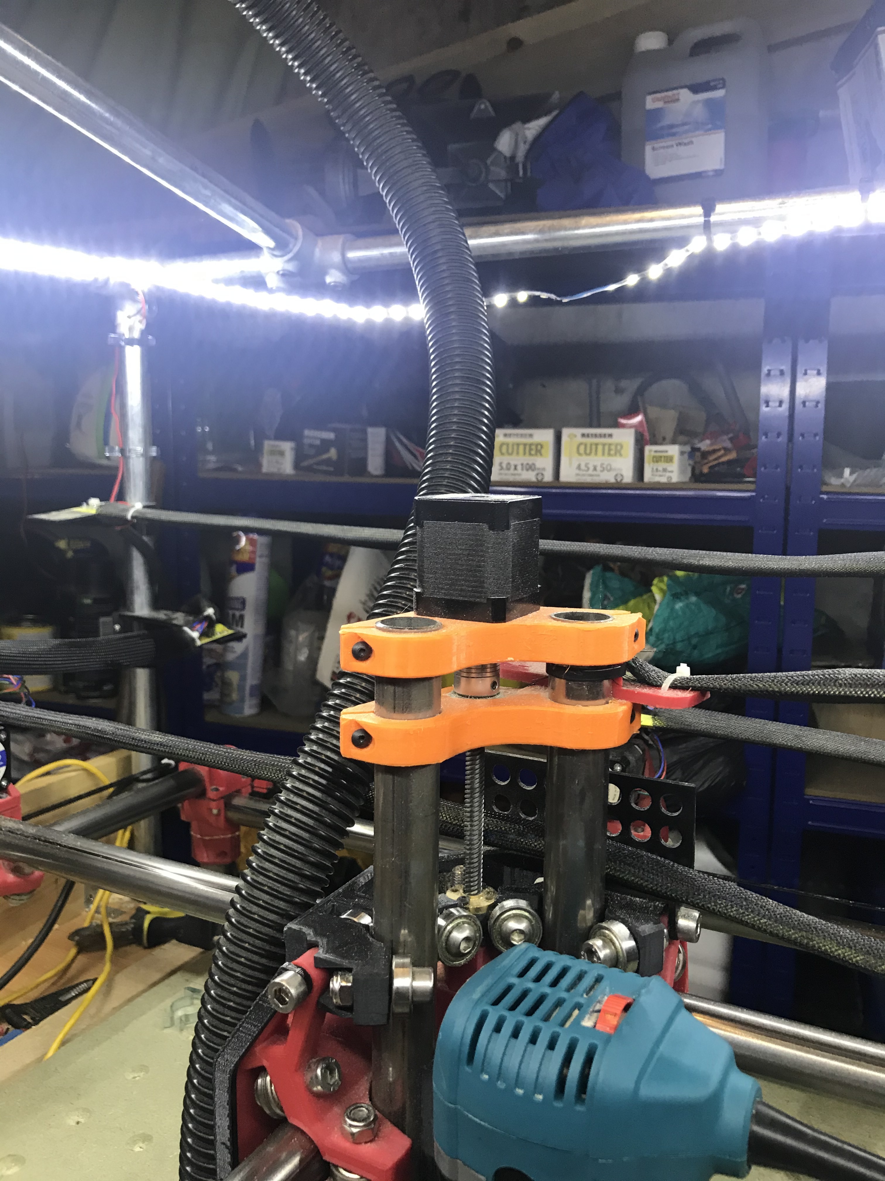
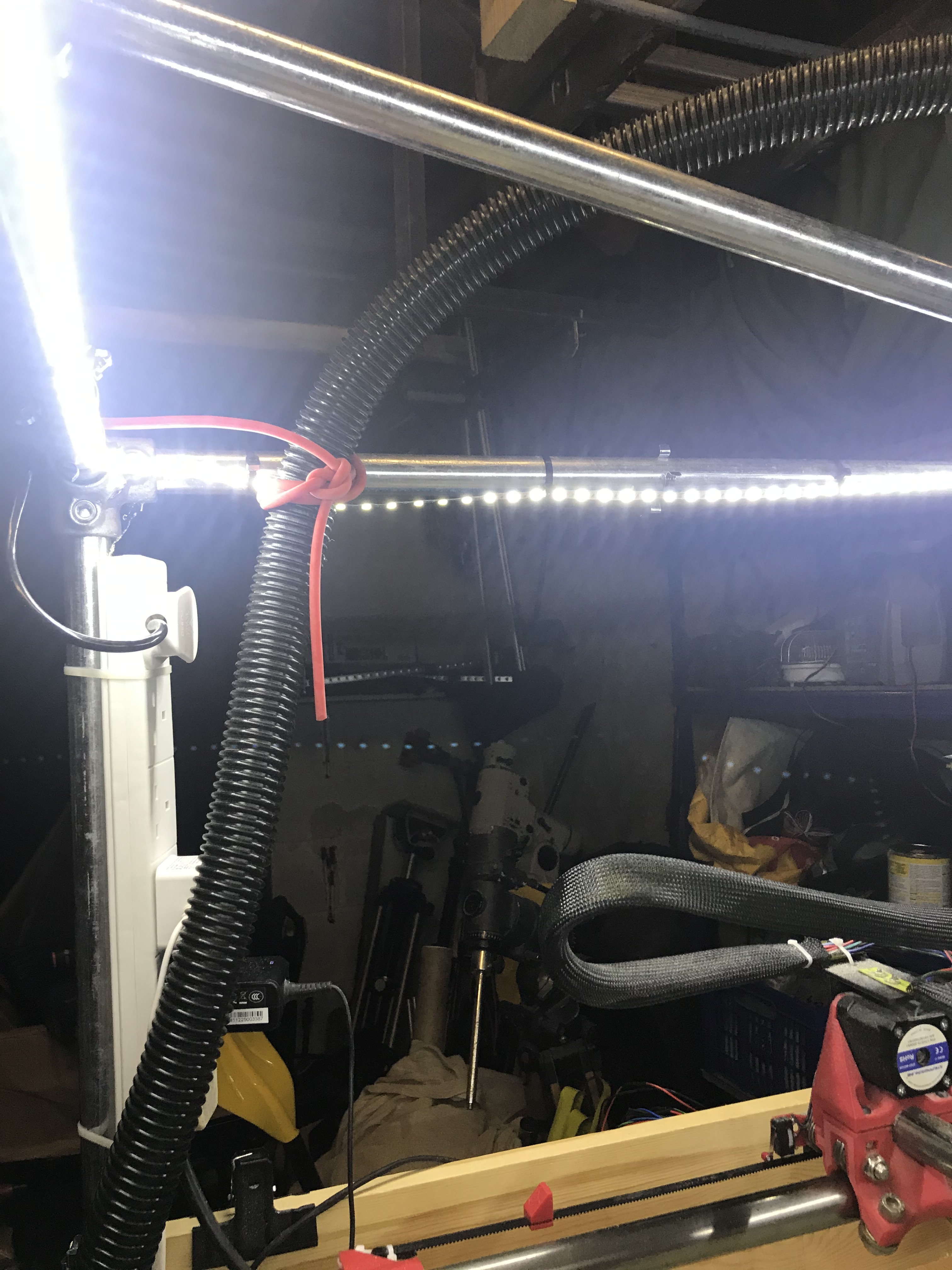
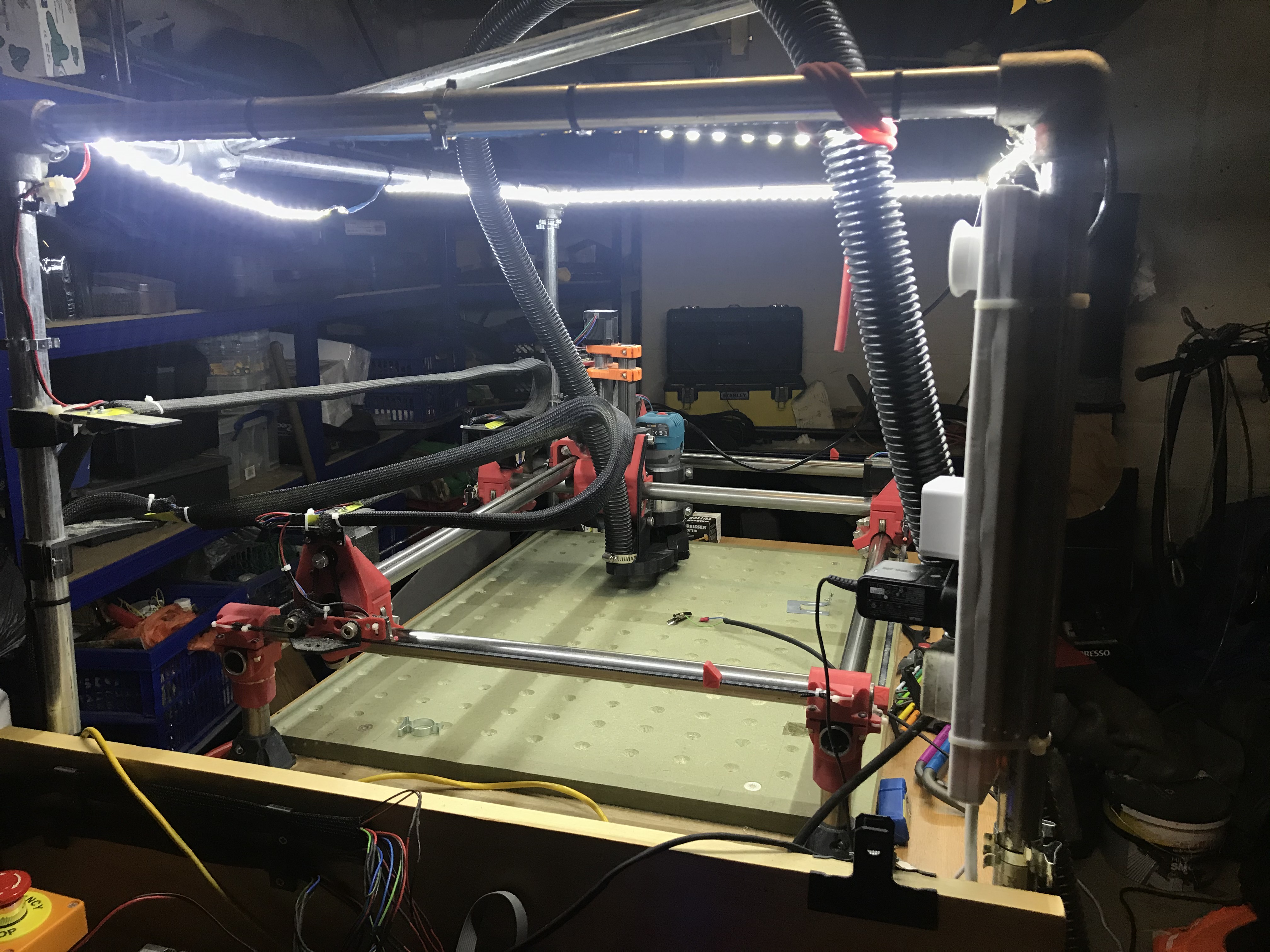
I’ve hooked the hoses up and am trying to route them to put as little leverage on the Z-axis as possible,
I’ve used red surgical hose (catapult hose) to tie the 40mm pipe on to the super structure frame, the natural curve of the hose keeps it mostly upright and there is little weight or leverage BUT there is some and I want to try and minimise it.
This is experimental and is a first effort. No idea what it will look like in a weeks time.
I’m interested to know how do other people route their hoses to reduce friction and leverage. I’m certainly not the first to do this.
Cool to see your vacuum idea working. It is well thought out. I elected to attach my hose to the top of my enclosure centered over the spoil board. The YouTuber Winston Moy used a hinge on the side of his enclosure and an arm off the hinge to keep his hose over the top of his router. I thought that was an interesting idea.
I have the router power cable (and will eventually route a dust hose) routed across a horizontal piece of 1/2” conduit that can swing over the work table with ease. The conduit elbows into a vertical piece held to the corner of the work table by two loosely connected conduit straps on the table leg. The vertical pipe rests on a stop block at the bottom. This allows the router to swing the arm over effortlessly when it moves.
Thanks for this. I looked through a number of his videos and couldn’t find anything that showed the hinge mechanism. If you know the specific episode can you let me know and I’ll shamelessly steal his ideas.