End stops inverting false or true

I don’t know if I am doing this right, or i am in the right area, if not sorry. I have a 4 axis xyz with another y motor called y2.
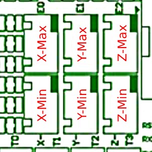
I have a btt skr pro v1.2 board in marlin how do I configure for do I make the y2. I think i am suppose to use E0. But also the end stops. I have x,y,z, and y2. How would I configure these. Also your marlin says like xmin and x max. what are these. I have 6 end stops plugs. x,y,z, e0,e1,e2. Here is what I have been looking at. I’m a little confused on this.
// Mechanical endstop with COM to ground and NC to Signal uses “false” here (most common setup).

#define X_MIN_ENDSTOP_INVERTING false // false // Set to true to invert the logic of the endstop.

#define Y_MIN_ENDSTOP_INVERTING false // false // Set to true to invert the logic of the endstop.

#define Z_MIN_ENDSTOP_INVERTING false // true // false // Set to true to invert the logic of the endstop.

#define I_MIN_ENDSTOP_INVERTING false // Set to true to invert the logic of the endstop.

#define J_MIN_ENDSTOP_INVERTING false // Set to true to invert the logic of the endstop.

#define K_MIN_ENDSTOP_INVERTING false // Set to true to invert the logic of the endstop.

#define X_MAX_ENDSTOP_INVERTING true // false // Set to true to invert the logic of the endstop.

#define Y_MAX_ENDSTOP_INVERTING false // false // Set to true to invert the logic of the endstop.

#define Z_MAX_ENDSTOP_INVERTING false // false // false // Set to true to invert the logic of the endstop.

#define I_MAX_ENDSTOP_INVERTING false // Set to true to invert the logic of the endstop.

#define J_MAX_ENDSTOP_INVERTING false // Set to true to invert the logic of the endstop.

#define K_MAX_ENDSTOP_INVERTING false // Set to true to invert the logic of the endstop.

#define Z_MIN_PROBE_ENDSTOP_INVERTING true // false // Set to true to invert the logic of the probe.
1 Like

Since you are using an SKR Pro 1.2 board, you can use the V1 maintained firmware and not have to do any configuration. You should be able to just put the binary firmware on an SD card, and flash your board. As for the end stops setting, they vary a bit depending on whether you are building a Primo or a Lowrider. For the Primo, V1 sets the end stops to:

// Mechanical endstop with COM to ground and NC to Signal uses "false" here (most common setup).
#define X_MIN_ENDSTOP_INVERTING false
#define Y_MIN_ENDSTOP_INVERTING false
#define Z_MIN_ENDSTOP_INVERTING true
#define X_MAX_ENDSTOP_INVERTING false
#define Y_MAX_ENDSTOP_INVERTING false
#define Z_MAX_ENDSTOP_INVERTING false
#define Z_MIN_PROBE_ENDSTOP_INVERTING true

Note that this endstop configuration is expecting you to wire your X and Y end stop switches normally closed. Using a normally closed setup is a bit safer since if a wire breaks, homing just fails to move the axes. If a wire breaks in a normally open configuration, the steppers will drive the axes beyond the stops.

You have to set EXTRUDERS=0. You also have to enable dual Y in configuration_adv.h.

The firmware in MarlinBuilder releases has these set and dual X. They should be a decent example.

what is the min and max sw. My board has z,x,y,e0,e1,e2,e3 thats what i don’t understand.

does marlin automatically set y2 for e0 plug on board. How is that done?

Looking at the pinout diagram, I can see your issue. I personally don’t have the SKR Pro board, but I’m 99.9% sure you plug in the end stops like this:

PinOut (1)

1 Like

image
what I did is pluged z end stop in z, the y into y, the x into x, and the second y2 into the e0. is that right? It looks like the main motors are calle the min, and the other y is called max. I only have one dual motor sequence. the others z and x are single motors. so I think the min and max are for instance in my case y is y min, and y2 is y max.

as far as my y2 motor goes where do I plug it into, the e1. since I use the y-max labeled plug you labeled. I really appreciate you guys helping me.

Marlin starts with the next open E motor. If you have an extruder, the Y2 will be in the next open spot, E1. Of you had dual X and dual Y, X2 will be first and then Y2.

At any rate, it isn’t hard to just guess and check. Just unplug the power before you swap anything. If you aren’t getting Y movement in E0, try E1.

In my experience, with the dual motor stuff, the compiler will error out if you make a mistake. If it compiles and uploads, it is probably one of those ports.

I should also mention that you can easily run two motors for one driver. It is safe and mostly has the same torque as dual drivers. All you have to do is wire your two Y motors in serial. The only downside is that you cannot drive them independently, so you can’t do auto squaring with two endstops.

so if I have x, y, z, and y2, y2 would be e0. that’s the way I got it. not the end stop switch for the y2 would be on e0 or e1. It shows y max kind of confused here.

would this be right for a cnc where endstops for z and using a probe. I have a z, x, y, y2
// Mechanical endstop with COM to ground and NC to Signal uses “false” here (most common setup).

#define X_MIN_ENDSTOP_INVERTING false // false // Set to true to invert the logic of the endstop.

#define Y_MIN_ENDSTOP_INVERTING false // false // Set to true to invert the logic of the endstop.

//#define Z_MIN_ENDSTOP_INVERTING false// true // false // Set to true to invert the logic of the endstop.

//#define I_MIN_ENDSTOP_INVERTING false // Set to true to invert the logic of the endstop.

//#define J_MIN_ENDSTOP_INVERTING false // Set to true to invert the logic of the endstop.

//#define K_MIN_ENDSTOP_INVERTING false // Set to true to invert the logic of the endstop.

//#define X_MAX_ENDSTOP_INVERTING false // false // Set to true to invert the logic of the endstop.

#define Y_MAX_ENDSTOP_INVERTING false // false // Set to true to invert the logic of the endstop.

#define Z_MAX_ENDSTOP_INVERTING false // false // false // Set to true to invert the logic of the endstop.

//#define I_MAX_ENDSTOP_INVERTING false // Set to true to invert the logic of the endstop.

//#define J_MAX_ENDSTOP_INVERTING false // Set to true to invert the logic of the endstop.

//#define K_MAX_ENDSTOP_INVERTING false // Set to true to invert the logic of the endstop.

#define Z_MIN_PROBE_ENDSTOP_INVERTING true // false // Set to true to invert the logic of the probe.
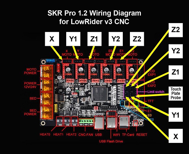
I am wanting a switch at eh top of my z axis to stop the motor if it goes to high. which will be the zmax. and the probe will be zmin. but where do I plug the probe and the zmax switch at on the skr pro. I Have a cnc with 2 y axis and z and x z rides on x. thanks

efine Z_MIN_ENDSTOP_INVERTING true what about a zmin why is it not false like x and y

IDK. You can test that with M119. I suspect E1, because it is assigned by ymax, not by 0,1,2

I can never remember. I thought NC was true, so that seems backwards to me.

That is a bit trickier. I haven’t tried that myself.

Zmin for the “probe” (but it acts just like an endstop, with G28).
E2, probably, but I am not sure for Zmax.

It is the opposite. You want the endstops to be “open” when the switch is not pushed. That is normally closed. The probe is normally open.

basically the z probe on a cnc uses the probe as endstop, and remembers that reading similar to a 3d printer bltouch. Is this right. Cause I no that it remembers where the bed is, I don’t think the bltouch probe check the bed distance while printing does it.

No, bltouch zeros to the bed. After that it retracts, and won’t deploy again until the next z zero.

I am trying to setup a switch for the top of the z axis, with also a probe plate on my cnc. I have four axis, and 6 plugs for end switches. Can that be done?

Based on my reading forum posts (no practical experience), yes this can be done. You don’t say what machine you are building. The LowRider firmware implements homing the Z axis up, and implements a touch plate using probing.

Reading between the lines, I’m assuming you are building a Primo. If so, my suggestion would be to build your machine using stock firmware and get everything (including a touch plate) running, then go back and implement probing to get your max Z. I did a quick scan of configuration.h for probing settings. There are a bunch of them. It looks like probing and homing both use the Z-Min end stop by default. This shouldn’t be a problem, but it also appears you can enable Z-Max end stop it you like.

The LR firmware doesn’t use the Zmax endstops as hard stops though. Only during homing. I think Dean is hoping to use it as protection against overrunning the Z max. I haven’t done that (but I remember the settings in Marlin).

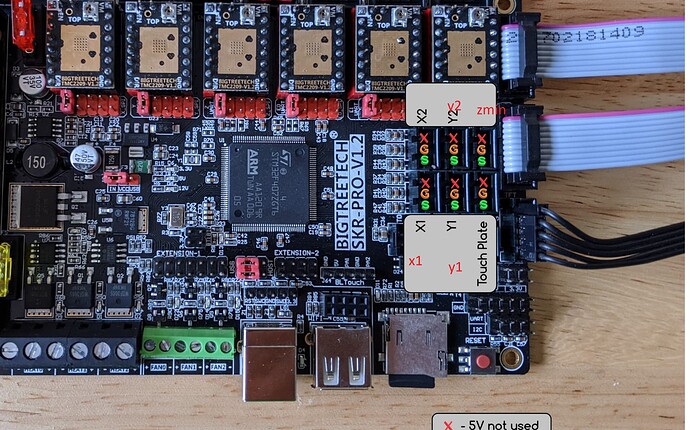
homes to Z-Max and then comes down to Z-Min to probe, I think this is in the firmware for skr pro. You think this will work, the probe I think uses z min and endstop to z max, this sound right to you. My machine has 2 y motors and 1 z and 1 x. So things look fine. I ran out of money so I am really care what I do. Think twice so I don’t fry anything. In the photo this photo I don’t have a second z motor, i have z, y1, y2, and x. Does any of the switch plug labeling of the switches change since I don’t have a z2 motor. If they do could someone label them for me. here is the photo.

I am wondering if z2 would let one of the others jump over to another. I’m am using xmin, z max, z probe, ymin for y1, and ymax for y2. Can someone help me on the labeling of the switches. I want to have a switch at the top of my single motor z axis, I guess that would be call z max. And also use a probe, I think that would be z min.


y2 here would be ymax, and y1 - ymin, x1 - would be xmin. and the x2 would be left no plug. Probe would be z min, and z max would be on z. that zmin there should be called z max sorry. Also in marlin do I change these like this.
// Min software endstops constrain movement within minimum coordinate bounds
#define MIN_SOFTWARE_ENDSTOPS
#if ENABLED(MIN_SOFTWARE_ENDSTOPS)
#define MIN_SOFTWARE_ENDSTOP_X
#define MIN_SOFTWARE_ENDSTOP_Y
#define MIN_SOFTWARE_ENDSTOP_Z
//#define MIN_SOFTWARE_ENDSTOP_I
//#define MIN_SOFTWARE_ENDSTOP_J
//#define MIN_SOFTWARE_ENDSTOP_K
#endif

// Max software endstops constrain movement within maximum coordinate bounds
#define MAX_SOFTWARE_ENDSTOPS
#if ENABLED(MAX_SOFTWARE_ENDSTOPS)
//#define MAX_SOFTWARE_ENDSTOP_X
#define MAX_SOFTWARE_ENDSTOP_Y
#define MAX_SOFTWARE_ENDSTOP_Z
// #define MAX_SOFTWARE_ENDSTOP_I
//#define MAX_SOFTWARE_ENDSTOP_J
//#define MAX_SOFTWARE_ENDSTOP_K
#endif
this is the way I set these anything I am missing.