Hey all! Forgive me if this is simplistic, I’m in the middle of a mental fog troubleshooting this and would like someone to tell me if I’m just being an idiot or not. I have been using my MPCNC Burly for awhile off and on and its been fun! (Really, all thanks in the world to Ryan and I regular promote this thing to my nerdier folk)
But recently i wasn’t paying attention, and maybe drank some beers, and i snapped part of one of my X endstops off. I didn’t have an exact duplicate of the endstop but i had two others ( i figured for dual endstops i should at least use a matched set per-axis?) so i am now using different endstops for X than for Y.
When i attempt to home X on the end endstops, it moves towards X0 about 3CM and then stops. Y still homes like a charm.
Do I likely just have the endstop wired incorrectly? Is there a firmware change I need to make if i change types of endstop? I pored over the configuration in marlin but didnt find any reference to specific endstop models like you see with stepper driver models.
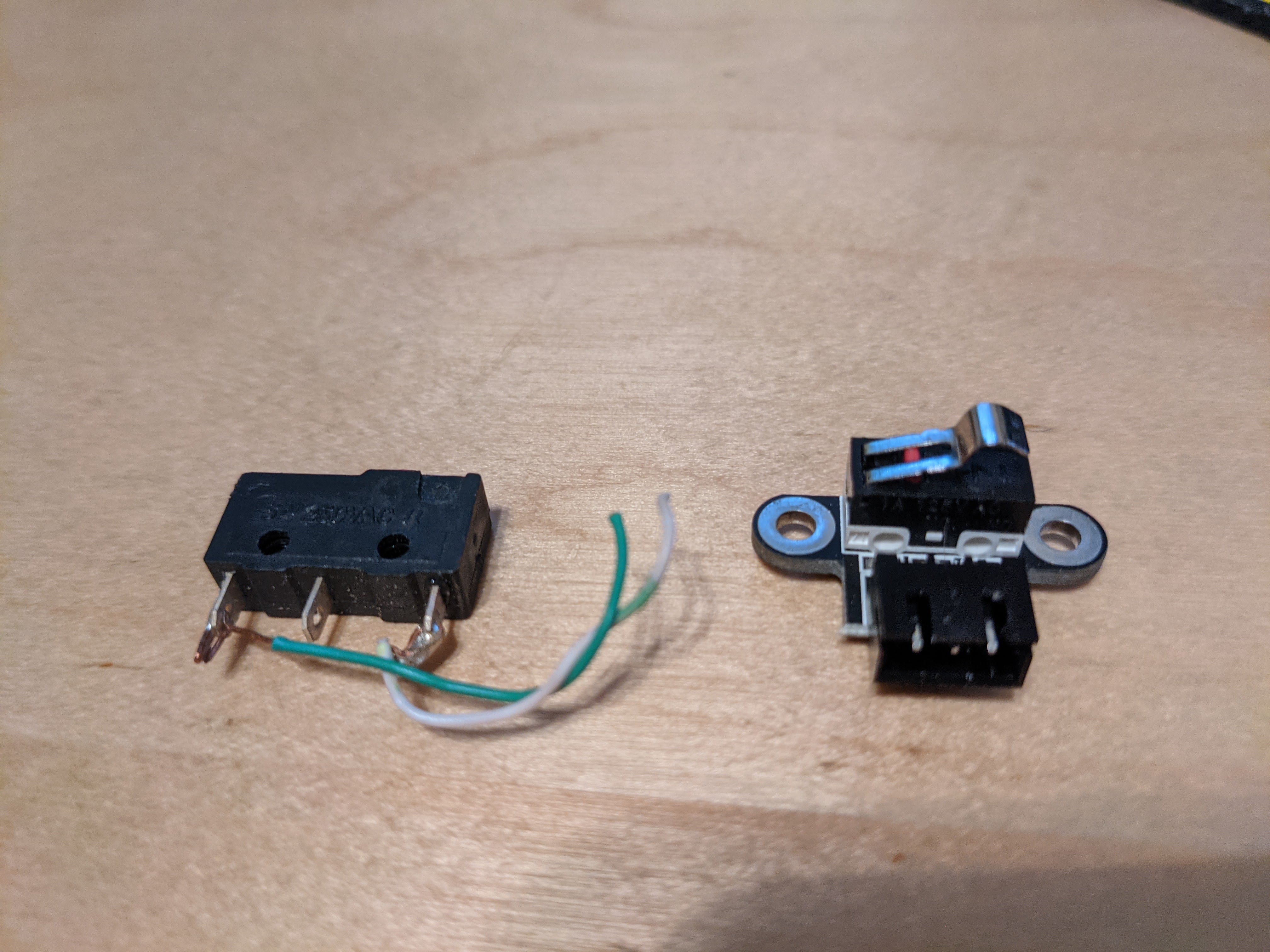
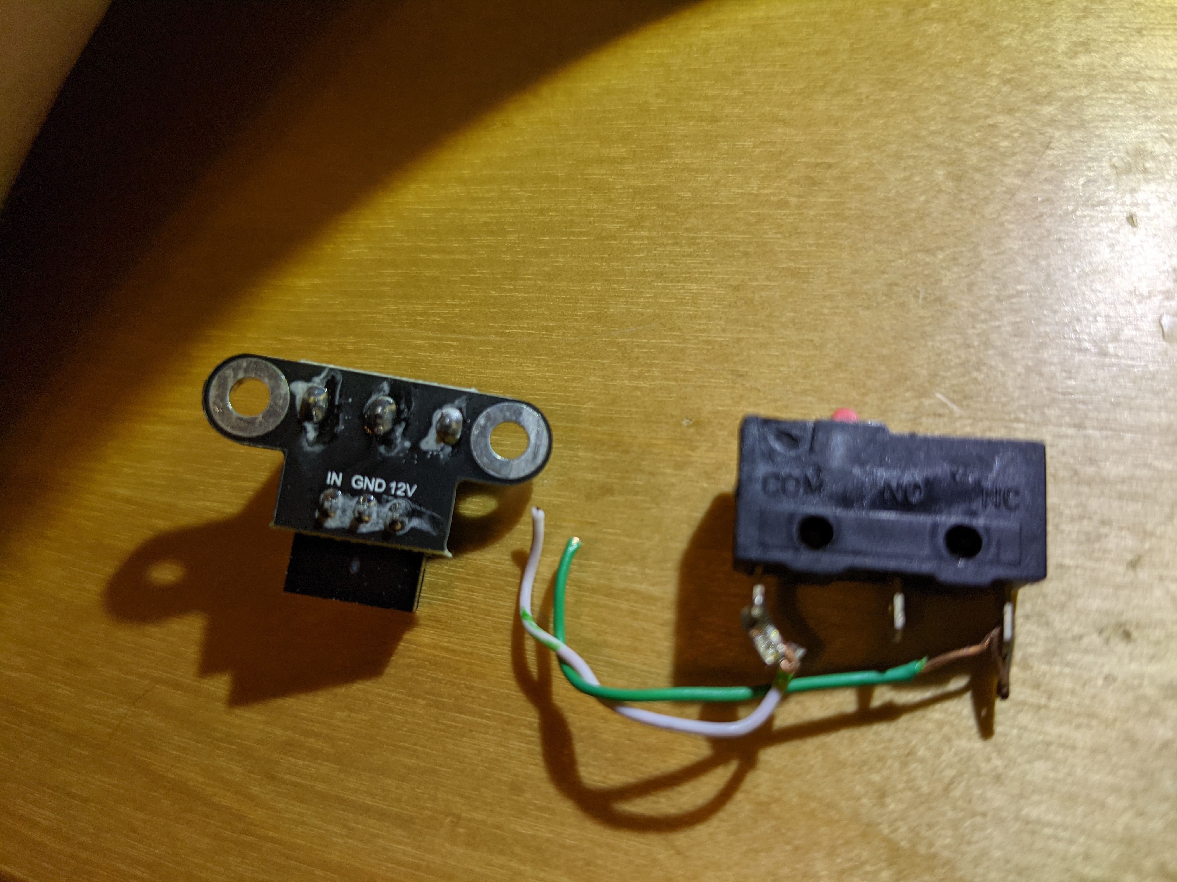
The new endstops have different indicators on the 3 pins. Old on the left new on the right:
Old Endstop: COM / NO / NC
New Endstop: IN / GND / 12V
Does COM correspond to GND and NC correspond to IN? Do I have a type of endstop that isnt comparable to/compatable with the old one? Do I need to use the same type of endstop on all axis?
There’s no direct relationship between 12V and any of the old switch terminals. The new end stop has an LED indicator, that’s why it needs the 12V. Usually these are set up as Normally Open (NO), meaning no signal gets sent until the button gets pressed, at which time the NO and Common (C) terminals are connected, closing the circuit. I have not had much luck getting them to work as Normally Closed. I’ve actually resorted to cutting the switches off and not using the circuit board.
Normally Closed (NC) is the standard for CNC limit/safety switches, meaning the signal is always flowing between the NC and C terminals, but stops flowing when the button gets pressed. This is preferred for “dangerous” machines as they’ll stop the machine if the circuit gets broken for any reason. This is a moot point for Marlin firmware as it only monitors the switches during the homing cycle.
I suggest shopping for replacement switches that match the old ones, and wire them as NC. I’m not sure whether Marlin supports different switch logic for different axes, but I’m sure if it does it means recompiling the firmware. That’s not too difficult to do, but then you need to remember to make that same change any time you upgrade. By going back to the original switch style you can continue to use V1 firmware updates as it comes “out of the box” rather than having to customize it every time.
Thank you both! Grabbed identical replacements which home just fine without any firmware changes, and then the desoldering trick will let me use the other switches on a different project where I wanted tiny ones