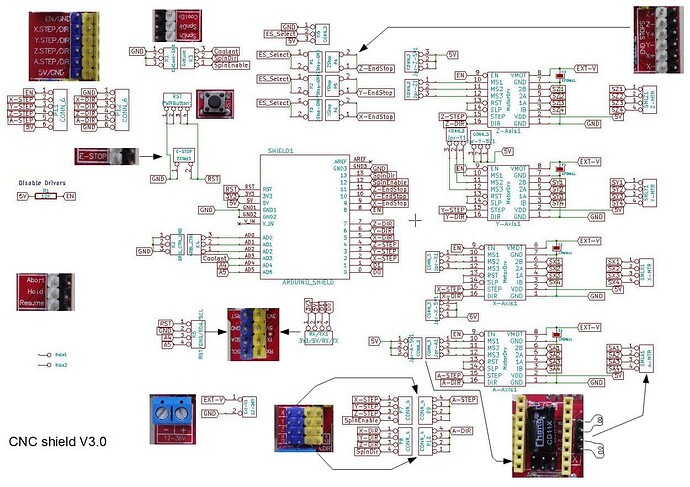
Endstop configuration

I had a board that liked to give false positives on the touchplate (NO), but I was using NC endstops.

The circuit goes as follows: The signal pin registers a “stop” when it is logic HIGH. In order to do this, there is a resistor between the 5V rail and the signal pin. When there is no path to ground, this raises the voltage to 5V (Or near enough) and the pin registers high, and triggers. When there is an NC switch, it shorts the signal to ground, registering logic LOW, which is untriggered.

If you have NO switches, you reverse the logic gates. The signal registers triggered at logic LOW when the switch closes. (Logic LOW triggering is more normal in electronics, actually.) I don’t like using capacitors to filter this because it also slows down the signal, and if you’re close enough to have noise, then you’re slowing down the signal by a random time interval. Not my idea of a good way to get precision. (Yeah, probably unimportant in the slower second pass, but…)

So there’s another way to filter out the false positives, and that is to wire an additional resistor between the 5V rail and the signal pin. This decreases the overall resistance, which means that there needs to be a much higher noise signal to drop the logic to LOW. The downside is a little more power usage at idle, because it will pass a bit more current to the pin, and a little bit more when the stop is triggered and it passes the current to ground.

Most of the pullup resistors that I’ve seen look to be about 470R. That’s about 10-11mA at 5V. The UNO datasheet says that you can have about 200mA on a pin. I added a 470R resistor on one of my boards between the 5V rail and the signal pin, which essentially halves the resistance, and increases the current to 20~22mA. For me, this was good to remove any false triggering for a NO switch, and did not introduce any appreciable latency to the switch timing.

Physically, what I did was put a 3 pin connector on the endstop switch, with one leg of the resistor on the end pin, and the other added to the signal pin in the middle, with the wires connected as you’d otherwise expect between signal and ground.
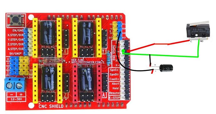
I thought that it is enough to connect it parallel on the connector on CNC Shield. I saw somewhere a photo where somebody had just stuffed a capacitor into the dupont-connector. I also saw pictures where someone had soldered it directly to the microswitch, but I think a better solution is to go for the board side…

I use simple PC817 optocouplers. In your case just adding a simple resistor to limit the current in the input diode of the optocoupler is sufficient. If you want some sort of visual confirmation then yes you would add an additional resistor and diode in parallel with that circuit. If you want visual confirmation on the opposite side then you need to add a power source on the side of the Arduino input circuit.

Just found this when googleing, seems to be what you said…

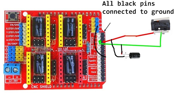
Is the black row of pins not ground? I was expecting it to be connected in parallel too. I am not as familiar with the grbl boards.

Well in the end one needs to be on “+” and the other on “-” side, otherwise there is no current going through, so unless there is something between - let’s say black and that gnd-pin I would assume that it does not matter if I put the capacitor like in the picture, or simply between black and white row pins. I am not a hardcore electronics crack just a guy who puts the stuff together and checks the circuit after the smoke clears out…

Maybe I am wrong, but I would also expect that NC type connection might be less sensitive to interference. If I am on 0V and get a little induced current, it might trigger the alarm but if I have the 5V on the NC switch I think some minor fluctuations do not matter, so it might not trigger the alarm. I think
in the end there is only one way to find out…

I think @jeffeb3 was saying this:

According to this picture the black strip being connected to to GND is configurable although I’m not seeing were is the selection jumper. It seems it can be configured to be common VCC instead of GND

EDIT: After a bit more looking the common selection was on older versions of this shield. Never the less you should check if your board has that option or not.

1 Like

Even if it is Vcc, the capacitor would work there either way.

Either the black pins are ground, the signal pin has an internal pull-up, and the logic triggers on a low signal.

Or the black pins are Vcc, the signal pin has an internal pull down, and the logic triggers on a high signal.

Either way, that capacitor is in the right place to filter out noise.

1 Like

Yup.
To make it easier you can use a non pol cap. The effect Will be the same. Also with a smaller cap the charging time will be smaller. Discharge should not be an issue since these internal resistors are in the Kohm range.

Sorry - I’ve been away for a couple of days. I may be the one that “stuck the capacitors in the connectors” that folks are referring to. I used non-polarized capacitors and slipped them into the connector between the signal and ground pins and they’ve been working fine. My control board is not mounted to the Burly base at all, so vibration has not been an issue so far. If they start to work loose, I might either re-crimp the connector ends to capture the capacitor, or I might just solder them to the underside of the board.

All those black pins along the edge are indeed a common ground.

2 Likes