The motor has 4 steps, ABCD, it goes from A to B… If you skip a step, its because you go from A to B to C to D and then instead of going to the next A, you go to the previous A. It goes those 4 steps really fast, and in the wrong direction so it sounds like crunchy gears, but it is really just popping back 4 steps.
I’ve just recently got my Burly running, using the CNC Shield v3.00 with grbl and I’m currently working on getting endstops working reliably. @CVG doesn’t mention what firmware they’re using, and that is a big element in getting good advice since there are a lot of viable options depending on the particular situation.
Unlike Marlin (which is the basis for @vicious1’s dual endstop firmware), grbl firmware does support “hard” limits ($21=1) that stop motion and put the machine in an alert state if any limit switch gets tripped. In its default configuration, Marlin ignores endstops except during homing.
Given that the CNC shield can’t support 5 drivers, the option of dual endstop auto-squaring is off the table (pardon the pun). You can do 2 switches per axis, but the min and max stops for each axis share a single Arduino pin. You can either do 2 normally open (NO) switches in parallel (one on each CNC shield pin), or 2 normally closed (NC) switches wired in series on a single CNC shield endstop pin. There are firmware adjustments needed for this to work properly, and the grbl config.h comments actually recommend against using 2 stops per axis. I’ll let you read why in the comments and you can decide which way you want to go.
The grbl firmware does support dual endstops and auto-squaring. It is a hardware limitation of the CNC shield and Arduino Uno, that limits it to 4 stepper drivers (3 ‘real’ axes and 1 cloned driver).
If you’re running grbl, you should be able to achieve the goal of not running into the mechanical limits of the machine with a combination of 1 endstop per axis and enabling both hard ($21=1) and soft limits ($20=1). You’ll need to program the max travel ($130, $131, $132 for X, Y, and Z respectively) for soft limits to be effective. That’s the route I’m taking. This also gives you the option of wiring the switch as NO or NC.
The grbl defaults expect NO switches and homing to the positive ends of each axis (Z up, X right, Y to the rear of the table), but these can be adjusted with configuration settings ($5 to invert limit pins, $23 to change homing direction) that are stored in eeprom. I’m starting with the defaults, as that means the gantry will move out of the way for installing work pieces. The CNC shield and grbl also support a tool probe separate from the Z limit switch, which I’ve also got wired in. Now I just need to find a place on the Z axis to put the switch to trigger at Z max.
What I’m finding is that my endstops and probe connections are very noisy, so they’re showing a lot of false triggers. This could be because I’m using a single 6-conductor cable for both motor and endstop conductors, or because I’ve got all the control circuitry shoe-horned into an enclosure that’s big enough to hold it all, but just barely. If you’re running separate wires to your switches you may not have this problem. I’m hoping to get the noise filtered out by connecting a capacitor between the limit switch signal line and a separate ground connection back at the board, but I had to order caps and am waiting for them to arrive.
The good news is that endstops are completely optional. I’m continuing to use the machine and tune other elements of my workflow while waiting on the parts.
I wish you good luck. Let us know how it goes for you.
(edited to clarify NO vs NC wiring options)
1 Like
A lot of great information here @ttraband. I’m confused about wiring the switches as normally closed (NC). This means that both switches need to be triggered before the end stop pin is triggered. Won’t work for min/max, and will cause the first stepper to drive against the end stop until the second switch is flipped in a min/min configuration.
The opposite. If either one opens, it will trigger.
How are they wired? You might have more luck with a smaller pullup resistor. Since the triggering is voltage, a floating wire will pick up emi and report a change in voltage with very little current. But if you put a 1kOhm resistor to 5V, it will sink that noise right away, and still be able to be pulled to ground when the switch closes.
I’m missing something. If the end stops are wired in parallel as mentioned, and they are both NC, then wouldn’t both end stops have to be triggered? Trigger one end stop, and the pin will still be grounded. You would need both end stops to be triggered/open for the pin to go high and the end stop to be triggered in the firmware.
Oh, I assumed they were wired NC and in series.
If you’re doing 2 NC limit switches on a single axis, you’d only use 1 of the CNC shield pins and have the two NC switches wired in series, and use $5=1. Tripping either switch opens the circuit. I’ll go back and edit my post to make this clearer.
This also explains why, with 2 switches on a single axis, a firmware change is needed, and why the comments suggest against it. Since the controller can’t tell which switch got tripped (whether NC in series or NO in parallel), it has to have logic added to infer which switch was triggered depending on the direction of the move that was commanded. If the homing offset ($27) doesn’t move the axis enough to reset the switch (and give the controller time to recognize the state change), the machine gets left in an alarm state and you have to de-energize the motors and manually move off the switch before (increasing $27 and) trying again.
I thought the Arduino Uno (that the cnc shield rides on) already had the pull-up resistors in place.
“104” ceramic caps did the trick. I just slipped them down into the JST endstop connectors at the board end of the wires as a quick test and I haven’t seen a false endstop or probe trigger since. I’ll probably do something a little more permanent eventually, but the control box isn’t connected to the machine, it’s hanging on the wall next to it. Since it won’t be subject to vibration this temporary solution may hang around for a while. At least until I need to go back into the box for some other tweak.
ATmega 328P have internal resistors. They are software enabled/disabled, a bit non-linear, act like a 30K to 40K ohm resistor, and (according to a few guesses by people better educated in electronics than I am), likely implemented using transistors. It is almost certain these resistors are enabled for the endstop circuit rather than leaving the pin floating.
Interesting to read all your explain information about switches, grbl firmware and codes. Thank you @ttraband for beautiful helpful.
I learned little bit GRBL Firmware, last time I was used it to test stepper motors with Vref Voltage, I will learn more GRBL Firmware after done step up with switches.
I found pictures that I can following to connection switches without Parallels and Series?
See pictures at below
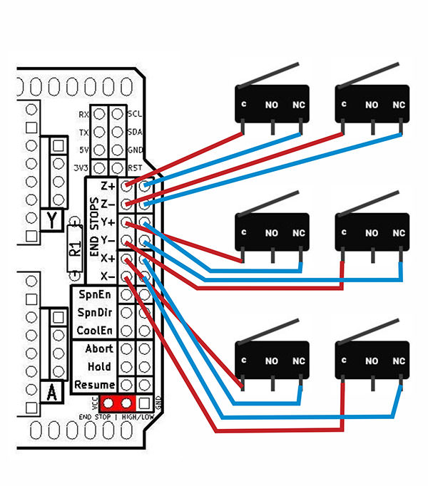
The pins on the shield are in parallel. Both Z+ and Z- on the shield connect to the same pin on the underlying Arduino Uno, and the same is true for X+/X- and Y+/Y-. You can check this with a meter or test light - the + and - pins on the each axis are the same. The shield makes it easy to connect 6 switches, but there are only 3 signal pins.
If you wire the switches as diagrammed, I don’t think (I haven’t tested it myself) that any of the axes will ever read as “triggered” unless both switches for the axis are pressed, which is, shall we say, mechanically unlikely in normal practice.
You can get away with NO switches in parallel, but multiple NC switches need to be in series. The feature list on the Protoneer web site for the CNC shield states
Limit switch pins have been doubled up so that each axis has a “Top/+” and “Bottom/-“. This makes it easier to install two limit switches for each axis. (For use with a normally open switch)
Check out Wiring Limit Switches for diagrams similar to those you provided showing NO and NC options. The CNC shield v3.00 connects X limit pins to Arduino pin 9, Y limit pins to Arduino pin 10, and Z limit pins to Arduino pin 12 by default. The Z limit pins gets swapped with Spindle Enable (pin 11) on grbl versions 9.0 or later when the variable spindle option is enabled in config.h. Later versions of the cnc shield (3.10, I believe) have been updated to reflect this change, but you can use the older shield as long as you understand the pin change. The cnc shields available inexpensively online all seem to be v3.00, as far as I can see.
2 Likes
The newer versions haven’t been copied in China yet not sure why may be no longer opensource?
Or someone got a million boards made and hasn’t run out of stock yet.
There are loads of posts in various forums saying “you can’t use the old shield with the new grbl” but the electrons running through the board don’t care what the silkscreen on top says.
With a little tweaking in config.h I’ve got a v3.00 shield running:
- 3 axes
- 3 endstops (hard and soft limits now that the capacitors have cleared out the noise)
- 1 probe connection (also relying on a capacitor)
- Variable speed (PWM) spindle control (no reverse, but the DW660 only runs one direction anyway)
- 2 individual relays for “flood” and “mist” coolant control (eventual vacuum hold-down and possible air blast for chip removal)
- 3 grbl “special” buttons (cycle start, pause, cancel)
Since I’ve got mains voltage running to the relays, I’ve got a ‘real’ e-stop that cuts all power to everything on the machine rather than wiring in the grbl e-stop/arduino reset, but I’ve got no doubt that it would work if I added the switch to the pins.
I could switch to a ramps board or one of @buildlog’s new modular grbl cnc controllers to get the additional drivers and endstop pins to support auto-squaring but I had the CNC shield in the spare parts box, and its doing all I ask of it so far.
2 Likes
This is my understanding too. I would hope they are enabled, but there are good reasons to disable them sometimes too (if you were switching between 5V and floating, you would want a pull down) so I’m not 100% sure.
It’s also common to just put them on the board between the micro and the header. I haven’t seen the grbl shield recently enough to tell you.
Regardless, the capacitor is working in a similar way, so good fix.
Yes I think they get the pin 12 (pwm)? switch confused and think it won’t work but I haven’t had trouble either. I use one all the time but haven’t used PWM
I understand clear what you explain, Can I following this switches wiring for my CNC Shields from this link?
What is difference between NC and NO?
Which is better or Which I can use NO or NC for CNC shields?
Normally Open (NO) means that the switch is disconnected and when you home the machine, the switch complets the circuit. Normally Closed (NC) means that the switch is connected and when you home the machine, the circuit is disconnected. NC is a bit better in case of a failure like a wire coming lose or breaking. If you try to home in an NC setup with a broken wire, the stepper just doesn’t move. In an NO setup, the stepper with try to drive past the endstop position until you cut the power.
@ttraband has the clearest description of what you should do:
If you’re doing 2 NC limit switches on a single axis, you’d only use 1 of the CNC shield pins and have the two NC switches wired in series, and use $5=1. Tripping either switch opens the circuit. I’ll go back and edit my post to make this clearer.
That is, you will only be using one plug on the CNC shield for each pair of switches instead of two. Note you can run the pair of wires for each switch to the CNC Shield and make the series connection at the CNC shield with just a jumper between one of the wires on each switch. No need for anything complex. I got to run or I’d do a quick drawing for you.
1 Like
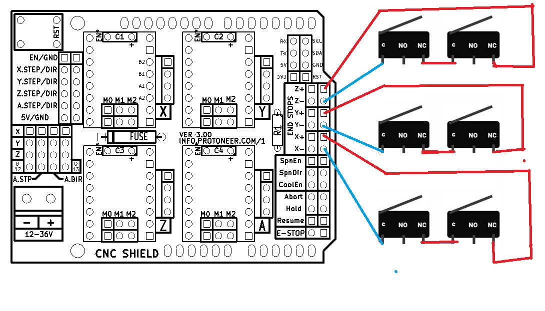
I tired drawing on picture of NC switches wiring in series diagram in MS Paint. I wonder this connection is correct?
1 Like
Yes, this is a correct wiring. There is no polarity to these switches, so things can be swapped around and still work. As one example, you can tie the NC from both switches together and then use the C wires from both switches to plug into the CNC Shield. From a practical point, it is probably easier to make this wiring connection at your CNC Shield. So imagine you have a red and blue wire pair coming from each end stop to the board. Taking the two switches for one axis, a red wire of one switch gets tied directly to a blue wire of the other switch. The other red/blue pair (one from each switch) gets plugged into the board…and it doesn’t matter in what order. This wiring at the board is the same circuit you have in your diagram, but with a longer wire run.
1 Like