Hi, sorry if this is a dumb question, still trying to figure this all out.
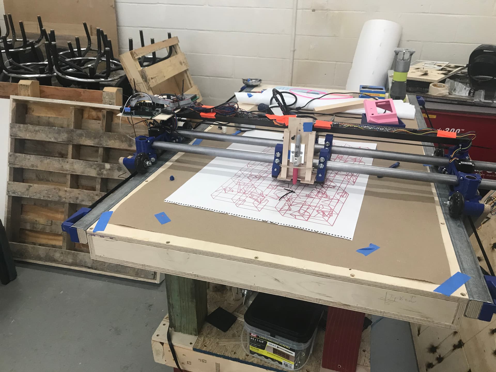
I’m working on a new LR build, rambo 1.4 from the V1 kit, series wiring. I’m not completely done with the build but I put everything together and ran some drawing files to verify wiring direction etc.
I’d like to add endstops (not dual just one in each axis) mostly to prevent over-travel but also to home at the end of cuts. The main reason is I already accidently hit “home Z” and tore apart my lead screw couplers.
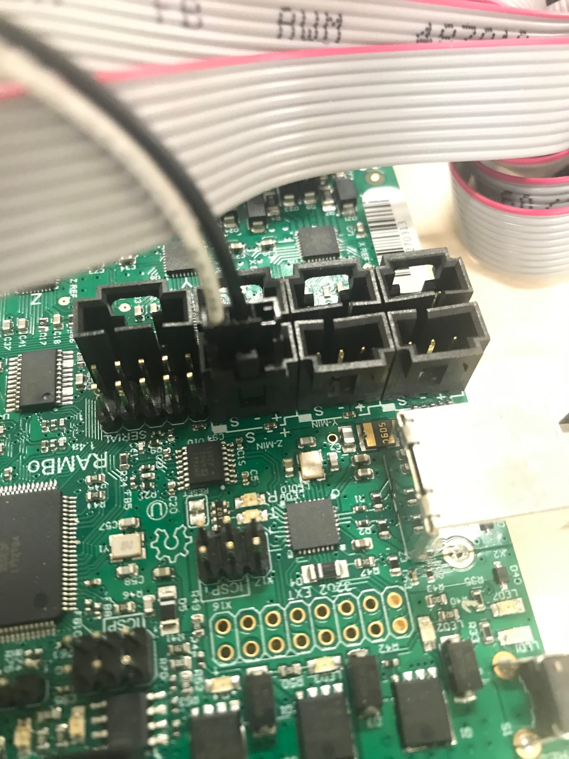
The problem is I cannot figure out how to properly wire the switch. I’m using the switches that came with the rambo kit so I figure they should work. The wires are connected to ‘s’ and ‘-’ on the board and I’ve tried both ‘nc’ and ‘no’ on the switch. No luck.
Additional Info:
It’s worth noting is that selecting ‘home x’ or ‘home y’ on the LCD moves the machine away from the origin about half an inch then stops. ‘Home Z’ moves the machine down.
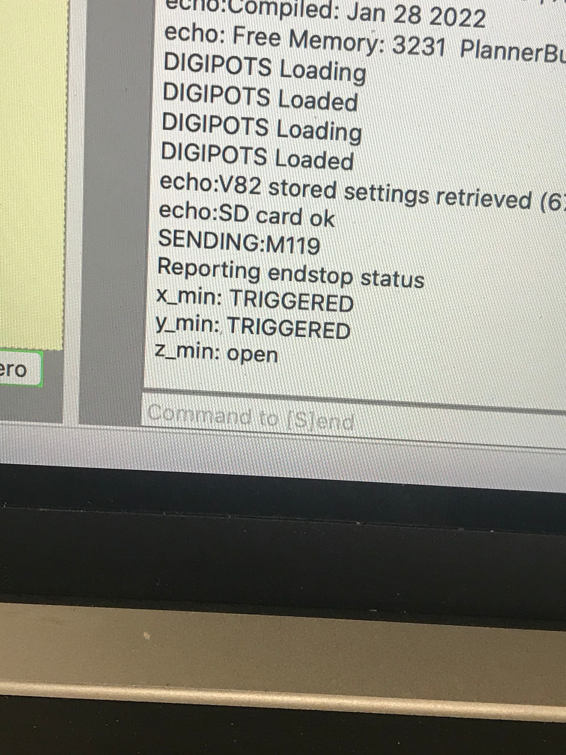
When I sent M119 (pronterface) I got this same message with the switch both open and pressed.
SENDING:M119
Reporting endstop status
x_min: TRIGGERED
y_min: TRIGGERED
z_min: open
The series firmware will still try to home Z downwards. You can change that, but you’ll have to recompile it.
The endstops are typically wired for normally closed switches. That is, when there is condictivity between the S and Gnd pins, it will read as OPEN, and when there is not, it will read as TRIGGERED. On most of the 3 pin switches, the correct pins are the outside pair. Do not use the pin in the center.
One pin per axis is probably OK, but if you’re going to do it at all… Why not go with the dual endstop firmware? 2 additional switches aren’t difficult to run or wire.
The settings you are seeing are exactly what you would see if you sent M119 with no endstops connected to the board. These settings indicate that your switches are not being read. This could be:
Plugged in wrong in the control board
Break in the wiring
Limit switch wired wrong
Note we’ve seen on the forum some bad assembly of the endstop wires that come with Rambo boards. I believe the issue was the connection to the spade connectors. If you have a multi-meter or some other way to check continuity, I’d start by checking the endstop wires that came with your Rambo board. Note these endstop wires are shipped by Ultimachine with the Rambo boards, so it is an Ultimachine quality control problem.
mostly to prevent over-travel
You are not going to get much help from endstops with this issue. Most cutting is done relative to the stock, so you would really have to jump through some hoops to prevent over-travel. I fuzzy on the firmware aspect beyond the normal, but I think you will either have to setup both min and max endstops switches for X and Y, or you will need make a firmware change so the compiled bed size matches your machine for softstops to be effective.