Endurance Laser

Getting ready to wire to my Rambo Mini board which I bought from the V1 Store. I’ve read a lot of posts this morning, most of them over a year old. So I’m wondering if I hook my 12v control wires to pin 45 and the ground, does the current firmware support the laser or do I have to flash it? Do I need to manually add gcode to setup?

Thanks,
Mike

I don’t yet have a laser, but I’ve been following and learning about the laser on the MPCNC, so I can answer some of your questions.

First, lasers are not enabled on the MiniRambo firmware. I know they are enabled on the Rambo firmware and the SKR Pro firmware. I know they are not enabled for Ramps. I’m guessing that Jeff/Ryan only enable the laser code on boards they have tested the laser on.

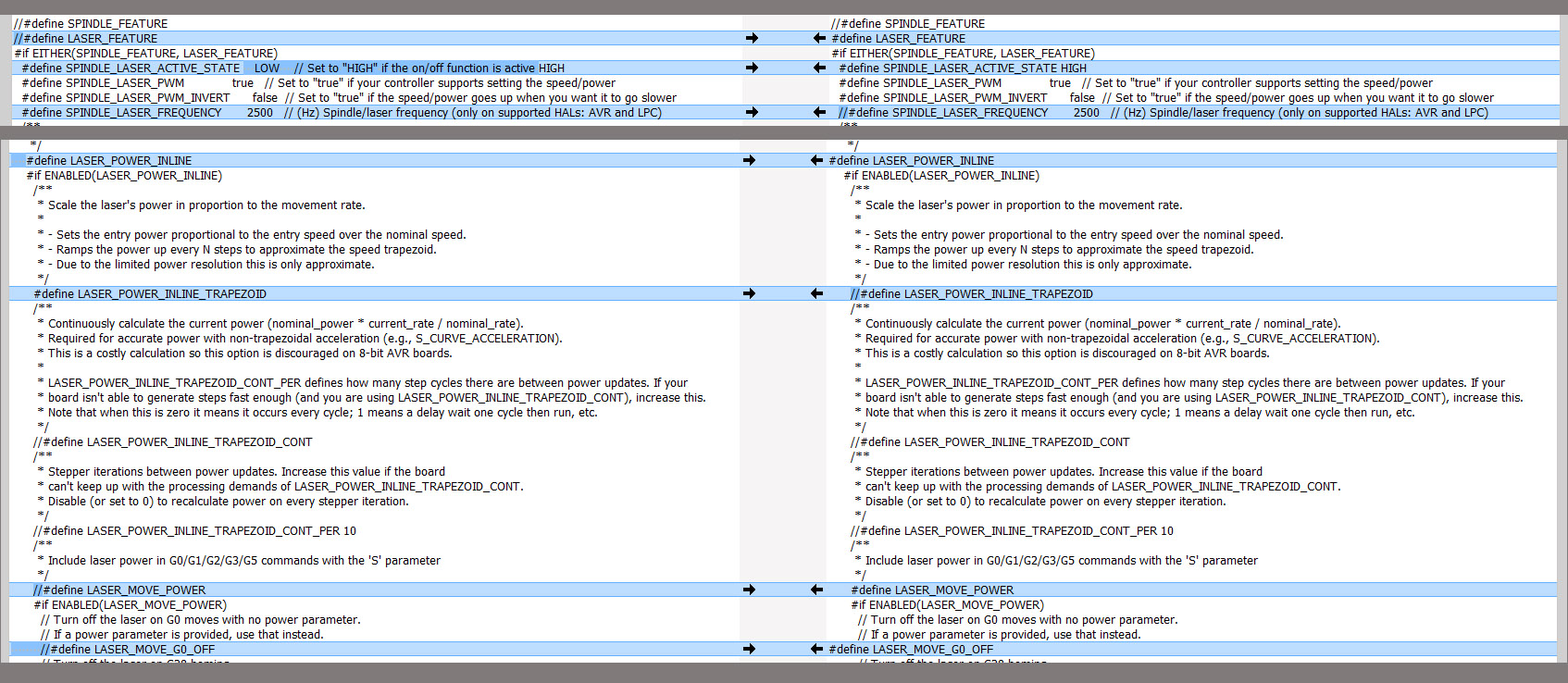
If I do a compare between the MiniRambo (left) and Rambo (right) for laser related differences in the configuration_Adv.h file, I get:

As for the pins, here is how they are defined for the MiniRambo (Marlin/Src/Pins/Rambo/pins_MINIRAMBO.h):

//
// M3/M4/M5 - Spindle/Laser Control
//
// use P1 connector for spindle pins
#define SPINDLE_LASER_PWM_PIN                  9  // Hardware PWM
#define SPINDLE_LASER_ENA_PIN                 18  // Pullup!
#define SPINDLE_DIR_PIN                       19

So on the MiniRambo, pin 9 is used instead of pin 45 for the laser.

The next problem you face is that I’m almost certain that pin 9 is a 5V pin, not a 12V pin. If you require 12 PWM to drive this laser you might be able to just swap pins between the current laser pin (9) and one of the two fan pins (8 and 6) and plug your laser signal line into a fan output plug:

#ifndef FAN_PIN
  #define FAN_PIN                              8
#endif
#define FAN1_PIN                               6

There is another potential way for you to approach getting your laser working. Before Ryan/Jeff enabled laser support in the firmware, people were driving their laser by using the fan pins and then having their CAM generate M106 and M107 g-codes to drive the laser. This would allow you to get your laser working without changing the firmware. Then if you decided to enable the laser support in the firmwere, at least you would know that your laser is working. If you jump right in to modifying the firmware, you won’t know if any issues are firmware or hardware.

Edit: I found this PDF on the Endurance website. It has a section on the MiniRambo, and they are using Fan1 and M106/M107 to control the laser.

1 Like

Do you have an endurance laser already? I don’t want to make you regret it (it works), but I have seen lots of not-so-great stuff about them.

I do.

1 Like

Thanks for the PDF, their website isn’t great for finding things - and I missed this. As for the rest I’m confused still, but will try that Fan 1 port.

Note that the pinout diagrams label the fan port used in the Endurance PDF as Fan1, but from a g-code point of view, this is possibly considered Fan 0. So when trying g-code to get the laser to turn on, I would try an M106 without a ‘P’ parameter, then with ‘P’ commands (P0, P1, P2). Also if you are using a separate power supply for the laser (most do), you need the ground of that power supply tied to a ground on your MiniRambo board.

My laser uses the 12v ttl, so I think I can plug right into the Fan port and not have to tweak the firmware like here:

Is that correct?

I’ve done a number of electronics/Arduino projects, but I don’t have a laser, and laser electronics vary from one model to another. With that said…

Your first step is to plug your signal line from your laser or laser control board into fan pin on your board. Note you are not drawing any significant power from this pin. It is only used to control the laser.

But there is a potential second problem you need to address. The ground from your laser must somehow be tied to the ground of your control board. If you are using the same power supply to power your laser as your MPCNC, then this happens automatically. But often these lasers come with a separate power supply, and in that case you need to figure out a solution. Sometimes there is a separate control board for these lasers that have a ground pin or a ground wire you can plug into your control board. If not, you are going to have to rig a solution to tie the two grounds together.

Robert,

I was able to set up and use my laser as described in the post I referenced above, plugged into the fan port and I did not need to flash my firmware everything seems to work fine. In the many posts I’ve read on getting the laser to work you are the only person I’ve seen talking about grounding the laser to the Mini Rambo - unless you are referring to the TTL- pin which I’ve done. If this isn’t the ground you are referring to could you elaborate on why?

Mike

I don’t have the technical background to tell you why you need to connect the two grounds. I just know that in my personal projects where I communicated between two separate electronic components, they need to share ground or the communication fails. I also helped one other person on this forum get their laser running, and adding a ground wire was required for the laser to work. Without the ground wire, there was no response from the laser. Note that if your laser is working, likely there is some ground connection of some sort between your laser and your control board even the connection is not an obvious one.

Thanks Robert , clearly I’m no expert, just learning as I go.

I believe the connected grounds give your controller and laser an agreed upon reference point from which to communicate. Otherwise, even if they both think they are talking 12V TTL, the reference to ground could be so off that neither on recognizes the other, thinking they’re always full on or off, depending on how the mismatch goes.

1 Like