Estlcam Carve offsets: Bug Report or Feature Request

@christian-knuell
In version 11.244, finishing offsets and finishing passes in general are not behaving the way I would expect.

Finishing passes are important because I want to use a high feedrate to clear quickly and a slow feedrate to get a precise final surface. Even with an endmill and a tool change to clear out a lot of the open space, there are still a lot small areas that are only reachable by the v-bit. To clear out these areas takes a very long time if the v-bit feedrate is slow.

The finishing offset in the carve tool appears to offset only vertically, and only for the carve operation, not for the pocketing operation.

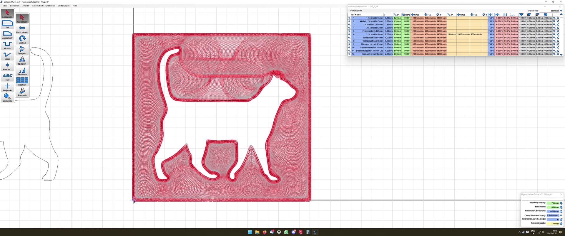
Here is an example with some simple artwork:
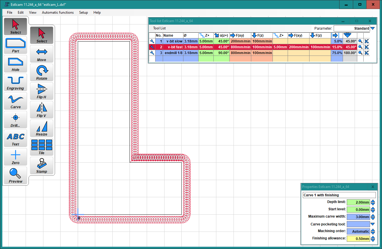
The ā€œpocketingā€ which defines almost the entire perimeter, is performed only once, with no offset, and the interior corner is performed twice with a vertical offset.

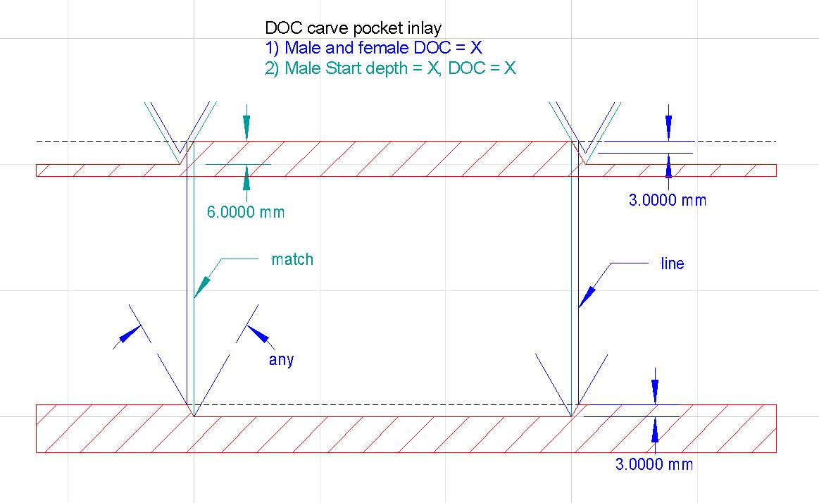
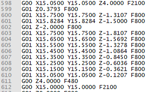
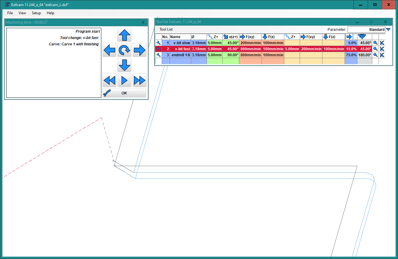
The carve itself occurs in this case by tracing diagonally downward along the upper (offset) line, then plunging to the full depth, and tracing upward along the final line. In the G-code, it is apparent that the vertical offset between the upper and lower carves is 0.5 mm (line 601 and 602), which is the finishing allowance that was specified. This means that the finishing allowance is a vertical allowance and not a radial X/Y allowance. This is somewhat surprising because finishing allowance is usually a radial (X/Y) allowance.

image

Also note that the finishing feedrate is not used for the finishing carve. The primary (roughing) feedrates are used for both the offset pass and the final pass.

Also, the carve operation is not respecting the conventional vs. climb milling preference.

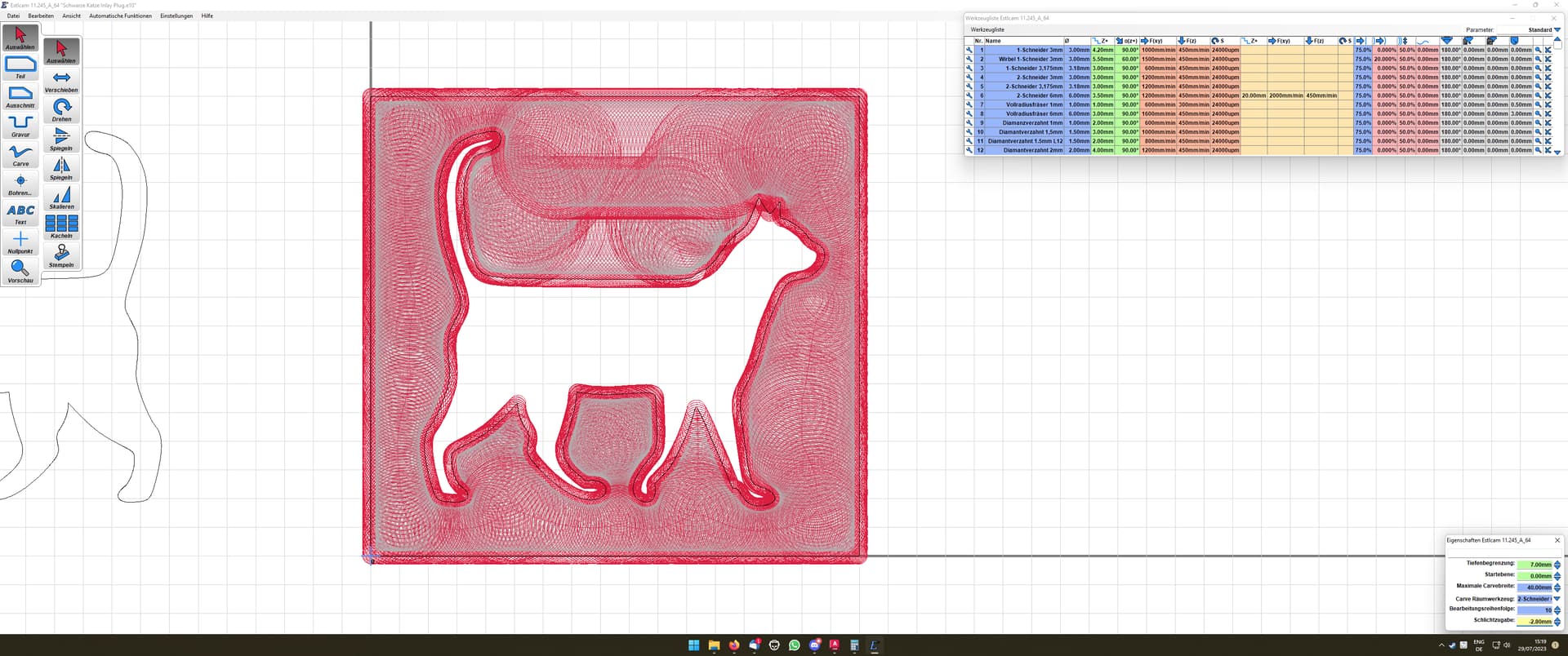
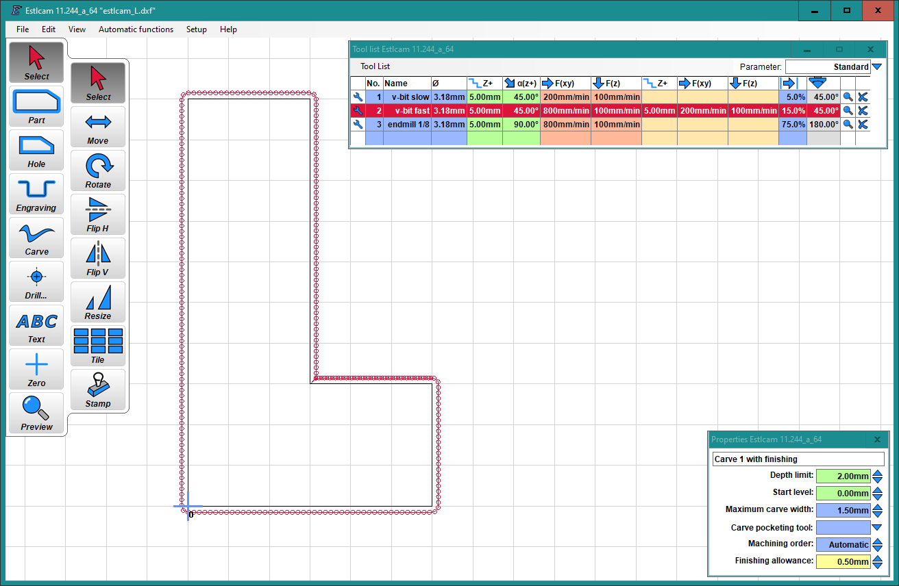
If the maximum carve width is reduced such that no pocketing occurs, then the perimeter is considered a ā€˜carveā€™ and not a pocket, and the result is two curves that are offset in Z by exactly 0.5 mm.


I thought I might ā€œsimulateā€ a finishing pass by raising the start level above the workpiece and increase the depth by the same amount. This would produce the bottom of the pockets at the same level, but all the perimeters of the pockets would be offset laterally due to the angle of the bit, and the carves would be raised in Z. Unfortunately, the start level cannot be less than zero. It might be possible to ā€œtrickā€ the machine with some G92 business but this quickly gets confusing and is very prone to mistakes.

Independent from achieving a finishing pass, due to an ā€œbluntā€ imperfect tool, I am wanting to fudge the piece widths using the depth limit and start level, but start level canā€™t be negative (above workpiece).

So to summarize, the request is:

  1. Finishing allowance should be treated as a horizontal allowance (even if it is implemented as a vertical offset for carves).
  2. Finishing allowance should apply to pockets generated by carve operations, as well as carves
    a. Pockets should be offset by finishing allowance (offset radially and full depth)
    b. Finishing pass should trace perimeters of pockets, not just carves
  3. Finishing pass should respect finishing feed rates
  4. Carves should respect climb / conventional settings
  5. (Request) would like to have negative starting depths available (above workpiece) to allow fine-tuning the width relative to the depth. This helps correct the last bit of error when preparing inlays.

Thank you.

1 Like

A finishing pass with a V bit would be a z change because moving it down will also move it over if it isnā€™t all the way inā€¦ If this is the same as a finishing pass with an end mill, then I agree with your statement that should be a horizontal offset.

Agreed, that roughing and finishing is purely a Z difference when not at the maximum depth.

One part I glossed over without emphasis is the amount of offset is different in X/Y and Z, depending on the taper of the bit. For a narrow bit with a low tip angle, an offset of say 0.1 mm radially in X/Y would require an offset in Z that is significantly greater than 0.1 mm.

As it is currently, a Z offset of the specified amount will leave less excess material than might be expected, if you are expecting the specified amount to be the radial amount of material left behind. I probably could have worded it better, but that is what item #1 is referring to.

I have run into the same problem (I think). I wanted to do inlays by mirroring it and making the plug smaller. I calculated that I roughly needed an offset of -1.4mm to make the plug small enough to go 5mm deep into the pocket. Thing is: Estlcam does show the correct toolpath, but ignores it completely. You can see that I once set -1.4mm and a second time -2.8mm. I let both programs run over the same object and it didnā€™t change anything at all.

-1.4mm:

-2.8mm:

The outcome of both of them is, as said before, identical, there are no changes at all in the outcome.

I experimented with finishing offsets with a carve and I couldnā€™t figure out what it was doing. I agree, the tool path doesnā€™t reflect the change in the visualization and it doesnā€™t change the size of the finished piece as far as I can tell.

In this case for the plug I think you can use a different strategy. I think an ordinary ā€˜partā€™ will give you the shape you need.

If your artwork has sharp corners, then cutting the pocket requires moving the bit upward in 3 dimensions to produce the sharp corner on the top surface of the pocket. This requires the carve strategy and hole or part will not work.

When cutting the plug, the bottom surface matches the (flipped) artwork and the carve strategy is not necessary. As long as the tip follows the artwork, the plug will come out the right shape, and an ordinary part strategy can achieve that.

Where it can get confusing is that the part strategy will offset by the tool radius and the tool tip will not follow the artwork. You can use a negative offset by the tool radius and then it will follow the line.

The other complexity is if you want a little bit of Z clearance, then you want the plug to be slightly oversize. This means the tip should cut slightly outside of the line. To achieve this, instead of offsetting inward by the tool radius, you can offset inward by slightly less than the tool radius.

Since the tip is cutting slightly outside and below the final artwork plane, technically this should use a 3D carve strategy or the sharp inside corners of the plug will be very slightly rounded, but this is small enough that it can be ignored.

1 Like

I know there are some workarounds, but that the setting doesnā€™t do anything is really annoying. It would have been so easy. I am back at F-Engrave for the plug. :slightly_smiling_face:

Christian just got back to me and told me that negative offsets for inlays are not possible. I asked him to then please say so in the tooltip and not show it in the toolpaths, so thereā€™s no time wasted trying to figure out the mistakesā€¦

If you look at the gray area (pocketing) in your two images youā€™ll see that it doesnā€™t move/change. If it was an X,Y offset the gray are would move inward with the offset. The Preview will confirm that there are no X,Y differences in the paths. If you rotate the Preview to the Z plane (much easier w/ v12) you will see that the change/offset is there and that the edit/main window properly represents that Z change.

Any object (e.g. that cat) that can have radiused corners (>= tool radius) will be much easier as a 2D inlay. I have yet to do 2.5D inlays so this is for a theoretically perfect (no interference) fit. The first plug path/pass should remove enough material to allow the 2nd DOC Start Level + DOC path/pass.

1 Like

Yeah, that should be easier actually, but Iā€™ve never given it any thought tbh. because Iā€™ve always done it this way. I am now back to Estlcam and F-Engrave, it does work (though I am fighting with the CNC because 0 moves 0.4mm to the left when doing the passes with the V-bit (and only then, not before)) and is not too much hassle if you know what you are doing. I use Estlcam for the carved out section, because I can work in layers and cut different pockets at different times whereas F-Engrave can only do the whole picture (which does not matter for the plug because I can split the different colours into different dxf. When thinking about what you are saying I remember going over the boards broinwood makes, none of them have sharp corners, all of them seem to be a bit round at least, he uses an endmill with a round tip as well. Iā€™d love to buy one of those (Sorotec Online-Shop - IntarsienfrƤser), but Iā€™d be scared to destroy itā€¦ -_-

/edit: He is using this one: https://www.amazon.de/Amana-Tool-46473-kegelfƶrmig-beschichtetes/dp/B07BRZDQ5J/ (Amana Tool 46473). Maybe I should have a look that it, but Iā€™d hate to round all the edges in text etc. that are normally sharp. Or are those bits so steep that it does not matter? Wonder how he does it (and no, I am not going to pay 140 dollars for itā€¦ :D).

Estlcam v11 carving only supports pointy V-bits, V12 supports V-bits with radiused and flat tips. With a radiused tip the bottom perimeter of the pockets will have a radius and the mating top side of the plug wonā€™t (using Estlcam). Using a flat tipped V-bit would solve that. As with 2D straight tool inlays, the drawing corner radii would need to be >= the flat tip radius to insure mating on the sloping (top to bottom) corners.

Aliexpress has lots of 6mm 15deg V-bits with .3-.5mm flat tips (.15 - .25mm radius, e.g. https://www.aliexpress.us/item/2255800092492380.html) that might be worth a try. I use 1/8 and 4mm versions (some w/ the maximum available .3mm flat) for regular 2.5D carves and havenā€™t noticed the corners not being perfectly square. I hear you on text inlays, using my favored 2mm straight bits for 2D text inlays really limits my font choices (Phenomena works well).

1 Like

Thatā€™s a neat font. There is another one called Simply Rounded (https://www.dafont.com/simply-rounded), itā€™s good as well for 2D.