Hi there!
So I started with an MPCNC, had a great time with that. Built an MP3DP, similar great time. Now I’ve built a Lowrider2 and am really having a blast!
So I have been sort of chipping away at a project for a while, and now that I’m confident with my Lowrider2, I began to tackle it yesterday. I’m attempting to make plaques for my sailing team that include some carved text and engraved lines (that part is going fine). Also on the plaque is a carved bathymetric map of Lake Michigan. This has been a bit of a process, as finding, converting, etc. the map required some new GIS skills.
Anyhow, yesterday, I cut my first one using 20"x20" birch plywood that’s hovering around 12mm thick. I decided my deepest layer should be 8 mm so that the bottom of the lake doesn’t leave the plywood too thin.
The map is using several pocketed holes and several islands (literally, and Cam-wise). I’ve adjusted the starting height for each new depth of the lake to account for the previously pocketed layer, and cut another 1.6 mm deeper than the last pocket.
I set this up in 3 jobs, for some reason. The carve was the first, and I had no real problems, 2nd I pocketed the first 1.6 mm-deep layer, with no problem. However, on the 3rd job (which was all remaining layers) the more layers it cut, it began to behave sort of strangely.
I was using a 1/8" 2-flute endmill, set to 2mm depth-per-pass, thinking that one sweep per layer should be fine.
I noticed about 2/3 through the job, it began cutting very shallow into the material, but then cut another, deeper pocket below. I figured that was just a quirk of using decimal depths. Then, nearing the end, I became a little skeptical that it wasn’t going to cut all the way through the ply (12+ mm, instead of 8 max). When I unbolted it from the table, the bottom layer was completely cut through.
All hardware is from V1. I know it’s not the physical machine because I’ve used it to build a cabinet with mortise & tenon joints, rabbets, etc, with no issue.
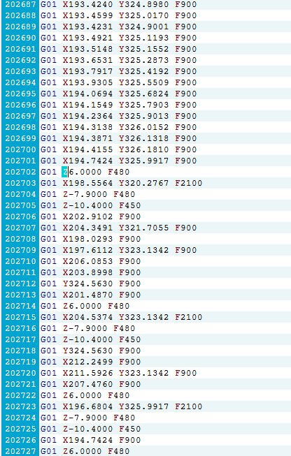
When I examined the G-Code, I noticed that later in the code the Z values are all over the place. They always return to the correct clearance height, but then will plunge into the material to depths that are nowhere in the intended toolpaths (-10.3,.-11.2, -14.4).
I’m suspicious that it has something to do with the fact that the distance between the edge of the hole and the island, sometimes causes the software to have to cut into the island (which I’d be okay with).
Since I’m new to the forum, it won’t let me upload a zip of the actual code, so I’ve included a photo of just one example.
Outside of combing through the G-Code and fixing all of the z values manually, any thoughts?