I don’t know whether you’re certain where in the system you’re having issues, but you can also rig a potentiometer to feed the PWM value as a way to test whether the dimmer board is reacting properly to that input. I actually permanently added a dpdt switch to the PWM input on the dimmer board which allows me to switch between “manual” control via the pot and having the nano do CNC control.
1 Like
Based on that I would think you have a good black/white contrast for the photodiode and its wired correctly. The 1.2-1.3 should be okay… but it might be too close? If I remember I played with the 10K resistor… changed the value of it. That will raise/lower the “Range” of the voltages. So you might get it to read 1.0-4.5 instead, for example and give yourself some room for error.
In my situation I think I was getting like 0.5 to 2.9 (as I probably did a poor job with painting the spindle) and changed the resistor to raise it.
Edit: The more I think about it may have been the other resistor. Basically changed the brightness of the LED in the sensor.
1 Like
I have absolutely no clue what’s going on. That sounds like a good way to test the dimmer, and I think I have some pots somewhere. The pwm out from the nano goes to over 4v almost immediately and I can’t figure out why I get 0 RPMS.
Definitely time to set it aside, though. I have a whole pile of stuff I need to make.
“Focused surrender.” Work on it until you get stuck, put it away, and the answer will come to you when you least expect it.
2 Likes
It occurred to me that the pwm out was sending 4 volts, so maybe I could use the pwm signal from the uno. I got nuthin. I double checked that I was getting voltage from the pwm (0.4v) and by the time I got back to the dimmer, the 60hz lights wouldn’t come on. Even not plugged in, they don’t flash like they used to. Even worse, the uno doesn’t like being plugged into it. All those Leds dim and cncjs keeps resetting.
Whatever the original problem was, I definitely have a bad dimmer now.
Well, I bought a replacement dimmer last week, and I got to a point on my next project where I’m waiting on my 3d printer, so hey, bust it back out, right? Wired up a pot to the dimmer, and it works just fine. Makes me wonder if I wouldn’t be better off going back to the dumb router controller (I’m going to be shrinking my primo soon and putting it on light duty, so it might not be so bad).
But first, I painted over most of the white so it’s just a pie slice now, and I painted my sensor housing black (it’s white pla). I might also try some clear tape over the sensor for some troubleshooting.
Update: I get values from 0.6V-4.8V…but only when I wiggle the connectors on the circuit board. I just have done a crap job there. I discovered it when I tried to probe for voltage on the led. I’ll update when I fix that.
ok, well, i seem to have a broken trace at pin 4 on the sensor connector so I jumped a wire to the two pins where it goes. Really nasty looking, but apparently functional. Remind me to tell you about some of the emergency plumbing repairs I made back at the buffet, lol.
Anywho, despite getting what seems to be really good readings from the signal wire, it still doesn’t work. Turns out that when I plug it in to the board, I ONLY get about 0.8V at that wire. I tried another pin, and I only get about 4.5 volts. Does that even make sense?
I’d like to help, but I have no idea what you are talking about. Maybe a picture would help?
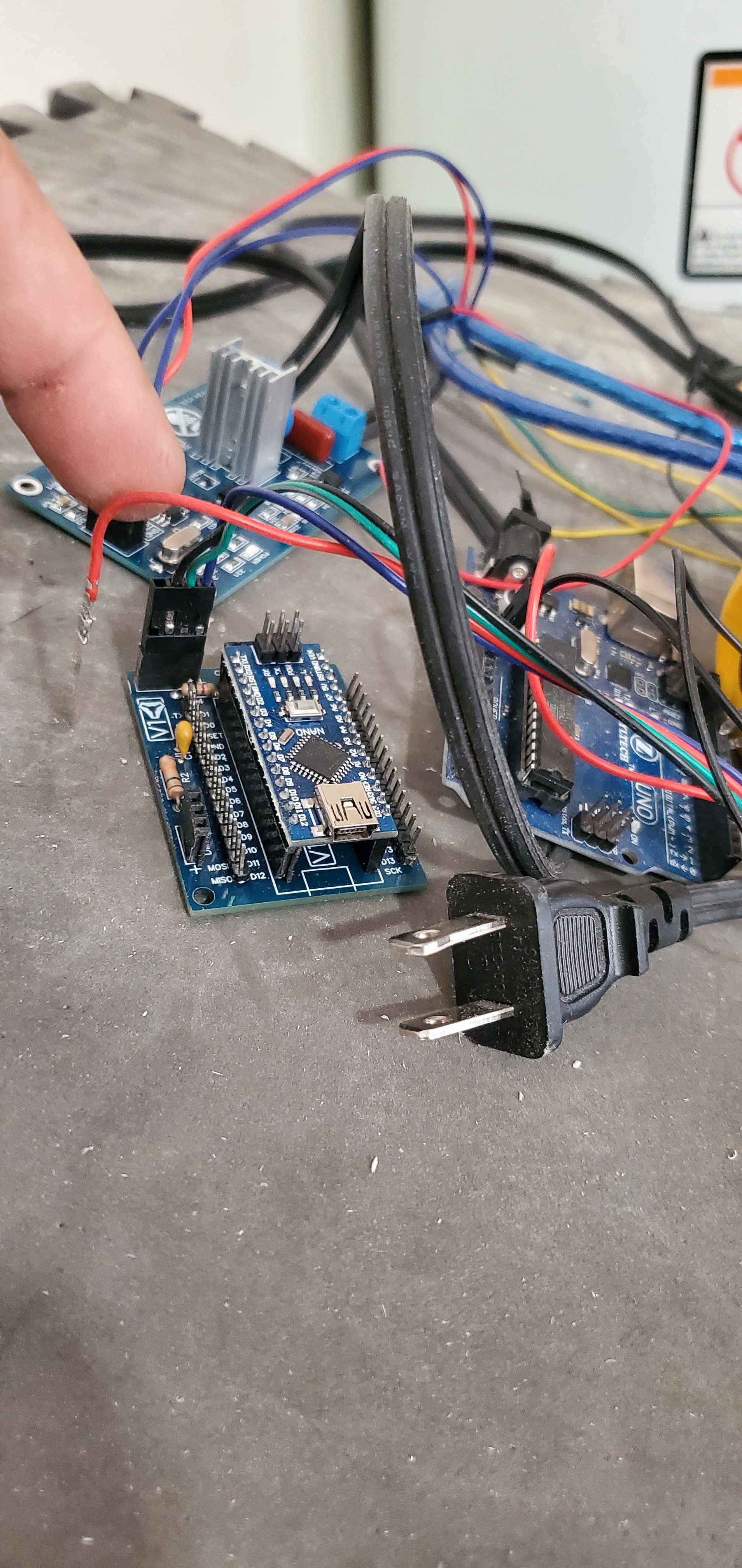
That plug comes from the sensor in the dewalt. I’m PRETTY sure I got the order correct per the note in the pid thread. The red wire is the signal from the sensor. When I measure the voltage drop from it to ground, I get something in the range of 0.6 to 4.8, depending on the rotation (by hand) of the tool.
As soon as I plug it in to the board, though, it goes to 0.8, no variation despite rotating the tool.
Curious whether I’d broken something else in the board, i assigned a different (unused) pin to the photo sensor in the sketch, plugged into that, and it went up to 4.8 (probably a feature of how arduino works?). I think this last step wasn’t very helpful at all, and I’m still not sure what I was expecting to learn.
I think you know this, but just to be clear, the 4.8 or 0.6 depends on the angle of rotation, not speed.
It may be that the input has the internal pullup in your second test?
Right, thanks. I’m expecting (based on some help above) that switch below 1.5V and above 3V tells the arduino that the angle has changed, and the sketch does some math based on this to calculate the RPM. Since my next immediate problem is that the nano is outputting 0RPM (with serial enabled), the pin dropping to a flat 0.8V and not changing seems like a reasonable culprit.
The sketch does define the pin with a pullup (excerpts below). I think pin2 is connected to the signal pin (primarily), a capacitor, a big resistor, and the ground. Maybe that resistor is dragging pin 2 from ~5V to 0.8? And since it wasn’t wired in when I tried the other pin, it stayed clsoer to 5V? Does it make sense to try this without the pullup? I only have a vague understanding of pullups, but I think the idea is to keep the voltage higher than 0?
//in declarations
const int PHOTO_PIN = 2;
//in setup
pinMode(PHOTO_PIN, INPUT_PULLUP); // Spindle RPM input pin
All the voltages having to do with the photo sensor are 5V so I doubt you have fried anything. But the fact that it drops to 0.8 makes me think your pin on the arduino is shorted to ground? Power the arduino and check resistance between the pin and ground pin with meter.
The way I read the schematic, that pin GOES to ground on purpose through the big resistor, no?
I also have a brand new board, and I just checked it from the sensor signal mounting hole to one end of the resistor mount, and from the other end to ground. That definitely happens, and I haven’t done anything to break that one yet. Have I read the thing wrong and the signal wire isn’t supposed to go there? I can power up the one I’m using after work.
With Pin 2 configured as an input and the board powered up it should have a high resistance to ground, or else out comes the smoke. Someone correct me if I’m wrong.
The 10k resistor acts as a pulldown to ground to avoid a “floating voltage” on the wire connected to Pin 2. For the 4.8v to disappear when you connect it to the arduino, it almost has to have a low resistance path to ground. Figure out where that path is. Could be the arduino pin. Could be a bad trace in the breakout board. Triple check all of your connections.
And make sure you have a shared ground across all of your components!
Looks like I have 9.6k powered, unpowered, from pin 2 to ground whether I pick it up on the arduino or from the plug for the sensor wire.
Also triple checked the sensor starting at the dot with 1, clockwise thriving the other 3 so that the darker piece (sensor of I understand correctly) has 1/2 and the clear piece (led) has 3/4. That goes left to right on the board 2431. 2 goes to the resistor, one leg of the cap, then d2. The other leg of the resistor and cap go to ground. 4 goes to ground. 3 goes to power through a smaller resistor. 1 goes straight to power.
I think I understand what you mean about a lower resistance dropping the voltage, but I can’t find it.