Usually, these higher current outputs are low side driven. So the ground is either floating or pulled down to ground and the 12V side is a straight shot to the power supply. If what you’re attaching is a high impedance load (one that doesn’t use any current), then you’ll probably need a small resistor between the low side and high. Just enough to pull it up when the output is floating.
IIRC, the rambo board is low side driven and it has a little resistor and led to tell you that it’s on.
My point is that they usually have a transistor for driving extra current, which you won’t need, since it’s capable of driving a fan. But they also have a diode (flyback diode is ringing in my head, is that the right term?) because there is a huge spike when you turn off the coil in the negative voltage direction. The diode lets it short across the coil instead of toasting your transistor.
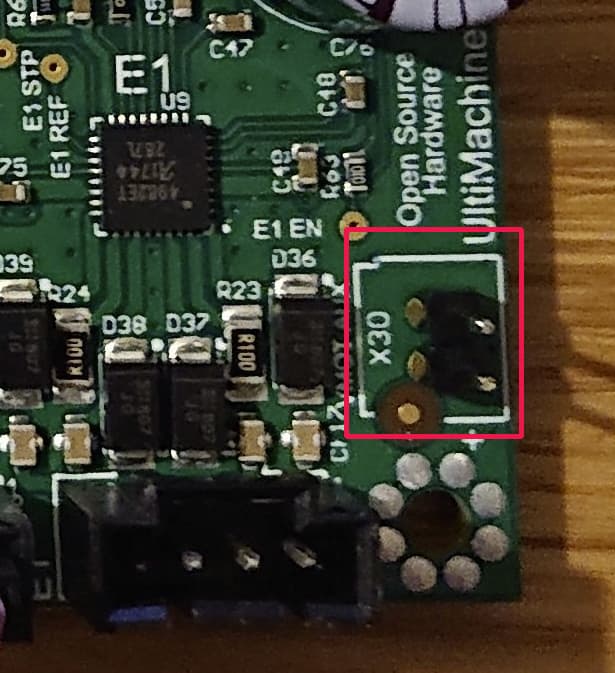
I’m trying to do the same thing (driving a relay off fan 2 to control my router.) So which of the two pins on the fan2 connector did you use as your ‘signal’ to the relay board? The left one or the right one? (looking down from the top) And did you need any pull down or up resistor to get this working? Sorry for my ignorance here, but I didn’t understand what low side driven really meant and what pins of the two on the fan 2 connector this applies to. Thanks for any help understanding this!
Kind regards,
Mike
Oh and should have said, it is a rambo 1.4 board and the relay is a relay module (dual) that has a jumper that lets me set whether it fires on the rising or falling edge of the input signal. Its currently set to rising so I am guessing that is not the ‘low side driven’, so since rambo is low side driven, should I set that jumper to falling edge?
Thanks again for the help,
MIke
found the schematic for the rambo 1.4 and can see one of the pins (the one on the right as looking down on the board as it is shown in all the pictures of it that I have seen) is just vcc (well vheat, same thing in this case). the other is the ‘high impedance’ input (the non high pin) that jeff talks about, and he appears to be right on about everything he said about fan 2 (about being low side driven and floating output value). So posting this mostly for someone that might have questions down the road, but still not 100% sure if I need to put a pullup on the ‘signal line’ of the fan 2 connector or not. And if I do, what sort of resistor value would you recommend? The voltage on that signal pin is somewhere in the ‘high’ range (I saw from 11 to 16 volts depending on how hard I pressed on the voltmeter probe), but when I issued the M106 command, sure enough it dropped low (.2 volts or something like that) and the LED came on as expected. So I have a feeling I would just use that signal line as is (with no pullup) with my relay module set to ‘falling edge’ (for triggering the relay), but I have a feeling that using a pullup is a safer and more of a best practice, but not really sure. What do you think?
Thanks!
Mike
This is an old post. So hopefully I understand what you’re asking.
We aren’t talking about the same thing when I say “High impedance input”. I am talking about the input to the relay being “high impedance”. If you connect a voltage to it, it will turn on, but not pull any power. The low side drive output is not at all high impedance. Impedance is sort of like resistance. It would work the same if I said High Resistance (but I have never heard it called that).
Your volt meter is a great example of a high impedance input. You can put red on 12V and black on 0V and there won’t be any current flowing through your meter (assuming you don’t have it in amp mode).
The key is, if we connect that output to your relay’s input, is it going to pull a lot of current, or is it just going to measure the voltage? More info about the relay would help. Unless you know what you’re doing already.
I think the fan output (low side) also has an led and a resistor to 12V. Which may be good enough for a high impedance input on your relay. If not, a resistor in the 1kOhm-10kOhm would be fine. There isn’t a perfect answer here. It isn’t doing anything precise.
Thanks for the reply Jeff, and clarification on high impedance. Got everything working well pretty much as I was describing above. If anyone is trying to make it work for them and has questions, just ring me up and would more than happy to help
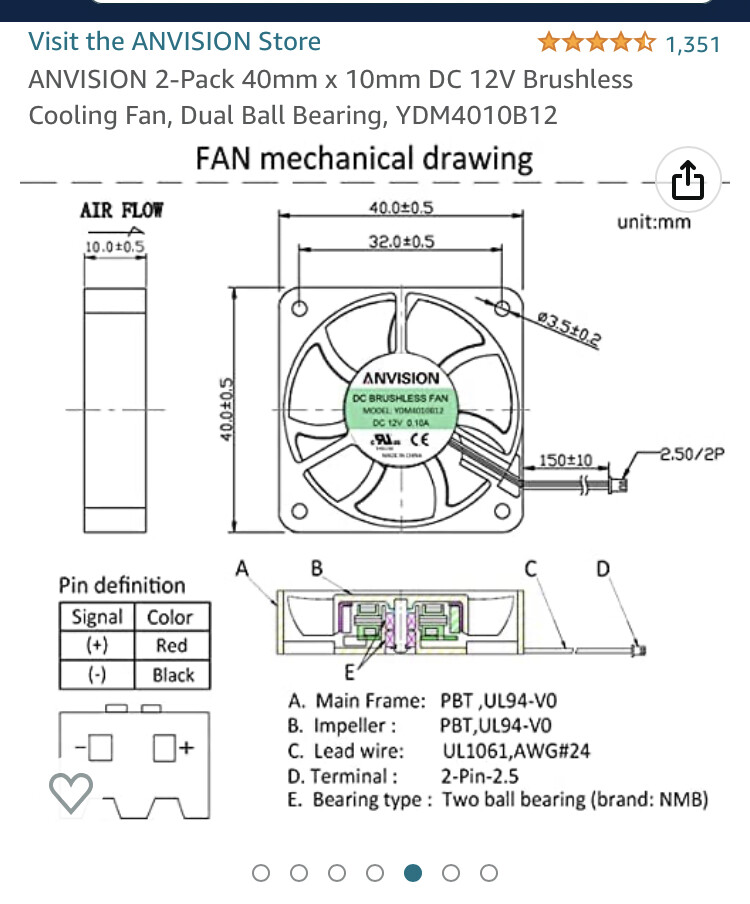
Hi I have a question about the fan being connected to Fan 2 on a Rambo board v1.4. Which is the signal and which is neg? I’ve looked on the schematic and on the bird itself but I can’t figure iwhich is which. Also do I need to configure a setting to get the fan to turn on?
I see an Icon of a fan on the Home Screen so not sure what that means.