Update: 2nd Oct 2020. I am going to perform a new test sometime this week. Please help me make that test better.
Original post:
As I am about to demonstrate, I am not an engineer - I am a degree-holding Materials Scientist by training and an IT professional by career. Try to not judge me too harshly.
Anyway, I convinced myself - from a very quick search on the internet and turning up a few research papers - that filling up tubes would improve stiffness and vibration dampening. Obviously I needed to test this cheaply with materials that I had at hand.
I cut a plastic water pipe in half - giving me 2 nearly identical pipes that could be easily bent. I filled one of them with PU foam, from a spray can. If there was to be any stiffening of the filled tube, it would be easily detectable. The sort of thing that I might be able to measure by eye.
Here’s the thing. There is no detectable difference in stiffness. None. Of course, this is blindingly obvious to a mechanical engineer (stop sniggering in the back, you lot). All of the strength of a pipe is in the skin of the tube (moment of area, I believe, is the relevant property). When I imagined that stiffness would increase I was thinking about I beams.
On the vibration dampening, again measuring by feel, I feel like that the filling helps. Now, I could measure this accurately but is vibration of the supporting pipes actually a problem with any of the current designs?
I could have and that was the original plan but honestly these things are so flimsy that they bend under their own weight. The 700mm lengths sag when held at one end. If the filling was going to make any kind of difference, It would need to keep the pipes straight - a significant change. I can tell you that it doesn’t.
There’s no such thing as keeping it straight. Every pipe bends, the questions is just how much. If you have very floppy pipes, then the foam may be making some difference.
I can appreciate it not working for you, and you wanting to just stop. But it might be useful to measure the difference, just to have a data point. Although it might be hard to end up with a result that means anything if the two pipes just naturally bend differently enough to make the foam difference in the noise.
Ah, I can see that I am going to need to write a longer reply but that will have to wait until tomorrow.
Here’s the short version: research papers suggested increased stiffening and vibration dampening. I needed a quick experiment to see if either of these things might be true for a large enough effect to make them worthwhile for further investigation. Hence my simple experiment.
My results: not worthwhile for stiffness but perhaps for vibration dampening.
You can fill these pipes with concrete and that will make them stiffer but at a massive weight penalty that could easily be fixed with a different geometry of pipe.
Yes, I wondered about that too. Some of it did run out of the end and I might need to leave it a while as I assume that it sets via a chemical reaction with air (oxygen). I could cut it open and check but I am going to leave it as long as possible to avoid a mess.
Concrete has been raised before and it is true that it would carry a big weight penalty. But it might be interesting in plastic pipes because it could provide a way of measuring how much (or how little) stiffness comes from concrete filling.
With a steel tube and a concrete-filled steel tube, the relative difference could be small, making it hard to draw quantitative conclusions. But in a plastic tube, it would be easier to see the difference in deflection under light loads and you could more accurately calculate the stiffness gained by the concrete filling. Then you could definitively say that concrete filling should increase the stiffness of conduit by 3.5%. But that 3.5% is small enough that it’s hard to measure directly.
Thank you for doing it and not just asking about it!!! This has been brought up so many times.
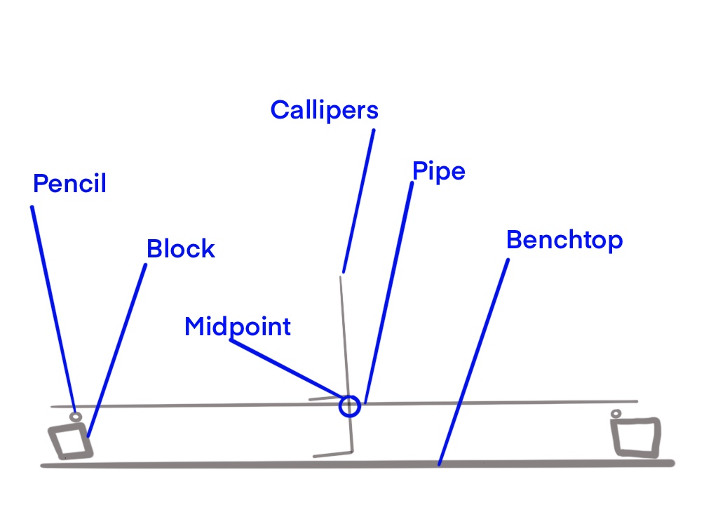
For my quick and dirty tests I set two point as far apart as possible and set the tubes on them I have used tables and chairs. I put a tape measure right behind it then a camera zoomed in right in front on a tripod. I take pictures before, then hang a 5-10lb weight dead center, take another picture. I take the weight off and take another pic, if the first and third are different I throw that result away. Repeat a few times. DOM only moves a few mm at a 5’ length, so any difference you notice would be significant.
I have my predictions but if you take some better measurements let us know!
@vicious1@jamiek@kockie-nl I only intend to do this once, as cheaply as possible. Please help me to do this in a way that will gain maximum acceptance from the community, so one ever has to do this again.
My thought is to use 2m (about 6ft) lengths of the cheapest plastic tube I can find “FLOPLAST PE-X PIPE - WHITE 22MM X 2M”.
@stpdhurts previously tried filling the tubes with an epoxy aggregate Concrete filled tubing “The added strength was not enough to compensate for the extra weight and the deflection actually got worse.”
Another user found that “I filled the static tubes with epoxy concrete for crush resistance (the only easily available 25mm tube around here is the kind you hang curtains on, chromed 0.5mm wall thickness steel tube; it is flexible enough to be deformed by the bearings, and tends to become a bit sloppy eventually); the filling did achieve the “crush resistant” goal, dampens vibration really well, but I got the concrete composition wrong (gravel too large, not enough fine sand, maybe not enough epoxy), so after a few trips of the gantry the exterior steel took the shape of the underlying pebbles / small voids and looks like the surface of the Moon” Concrete filled tubing
I think a camera setup with a tripod is particularly good because it does not interfere with the system itself. Especially for small deflections and low loads where calipers can get fiddly.
I think another factor is the amount of deflection should be relatively low, ideally in a similar range as the tubes of the CNC machine. It’s possible that the deflection vs. load could be nonlinear, say if the concrete develops cracks it might be stiffer at small deflections and become less stiff at larger deflections. This could raise an objection that the test is showing concrete to be worse than it really is at small deflections that would be realistic for the inside of a DOM tube.
This implies that the measurements should include small deflections, which might require small loads or shorter spans. And this gets back to the optical measurement technique that is easier to feel confident about.
I have some Portland Cement that I bought for something else. I might buy some PVC and try an experiment also. I also have some white silica sand so I can try both cement by itself and cement with silica sand.
I have bought a metric dial gauge (I have other uses for this so I’m not counting it as a cost - mental gynmastics) so I am confident that I can measure the deflection down to about 0.02mm accurately which should be good enough. I can document the deflection with a camera at any angle then.
As for loading, I suspect that a few kg is all that is needed. I estimate the static load of the CNC mill, plate, motors etc will be less than 4kg per rail. I saw previously that the torque loads are the order of 2kg ish. A maximum loading of 6kg should be enough. I will start small and work my way upwards.
Failure of the concrete would rule it out as a suitable material.
Edit: in any case, the loading should produce a linear stress/strain relationship (Young’s modulus) otherwise you have strayed into plastic deformation or, in the case of concrete, cracking. I think that I’ll also measure deflection of some stainless steel and copper pipes that I have lying around as a control sample.
I agree it should be linear over the range we’re interested in. If the naysayers are correct, the stiffness of concrete (or concrete within plastic) could be much less than the stiffness of steel tube (with or without concrete), so even a few kg might be too much. Again I agree, it’s good to start small as you said, just make sure you start small enough that you don’t have excessive deflection right from the start.