If you want to flip a piece to mill both sides, or if you want to mill negative and flipped positive shapes for inlay, it’s generally accepted that the machine needs to be square.
I got to thinking, a skewed machine would produce a rhombus instead of a square. Such a rhombus would usually not be symmetrical about an X or Y flip, but it would be symmetrical about a diagonal flip. The exact location and angle of the axis of symmetry would depend on whether the X or Y or both were skewed, and by how much. But while the axis of symmetry might not be predictable relative to the table, it will always be along the line if you were to jog the machine from (0, 0) to (300, 300).
So I thought I would do an experiment, deliberately skewing the machine and trying a flip along the X axis and a flip along a diagonal axis.
I used an asymmetrical shape to make it clear which were being flipped which way:
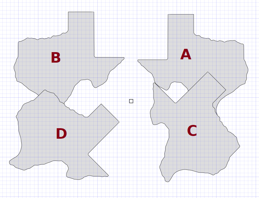
In this case B and A are flipped horizontally relative to each other, and C and D are mirrored diagonally. The displacement between C and D doesn’t need to be diagonal, it’s just the orientation of the mirroring that matters.
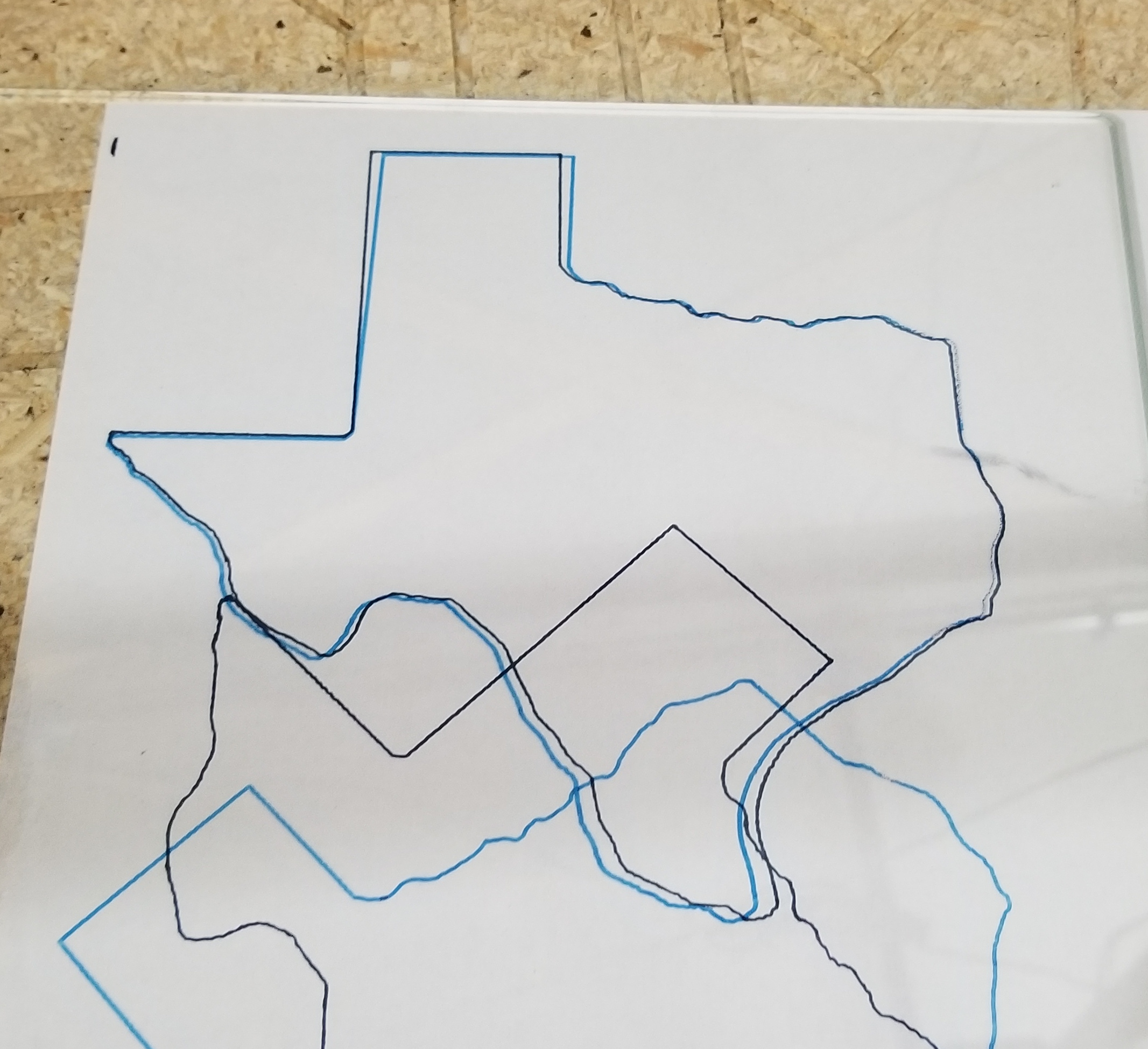
I have misplaced my transparency sheets but I have glass, so I drew these all in one shot, guaranteeing they all have the same skew:

Then when I flip the glass and overlay onto the paper to compare A and B, the shapes clearly don’t fit due to the skew:
But there is a night and day difference with shapes C and D:
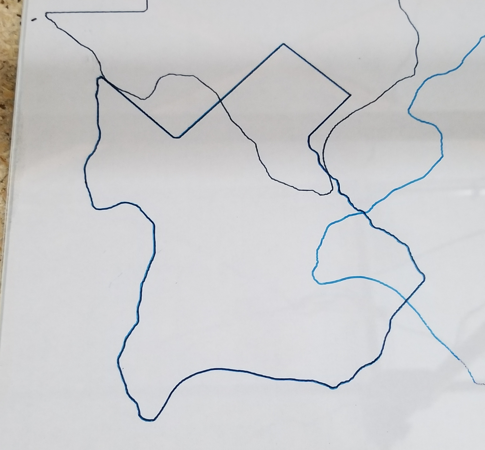
Especially given that the skew is huge (on purpose), I think this is pretty remarkable. For inlay or double-sided work, tiny errors in squareness can be big problems, but perhaps it can be resolved by simply using the right orientation of the workpiece and flipping axis. It is important to keep the steppers energized through both operations of course, so the skew is the same.
At a mathematical level, a skewed square is not quite a rhombus. The skewed side length is slightly longer by one over the cosine of the skew angle because gantry motion of X will cause diagonal tool motion very slightly longer than X. But this is a very small effect. 1 degree is quite a lot of skew (5mm of skew over a 300mm width) and the cosine is 0.99985. A half degree of skew would be a length error of 0.99996.
I thought this was interesting and I hadn’t seen this talked about before. Maybe two-sided milling doesn’t require such precise squareness after all.

