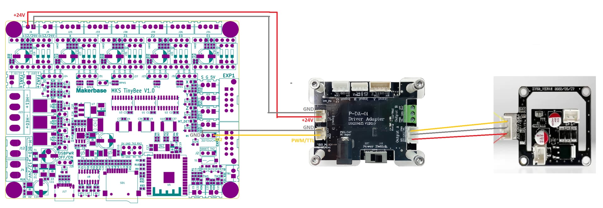
I’m printing a daughter board support for teh LR3 case to put the adapter baord inside…
Only problem I have left now is that the laser briefly turns ON when I power on the main board…
I may relocate the switch from the adapter board to shut the power down manually, but it’s a bit impractical…
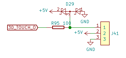
That may be just the signal line ‘floating’ during the boot sequence… or your data pin is actively being driven by the uP. You could try a (say) 10k resistor between pins 1 and 3 on the 3D Touch socket…
Having said that, I see you already have a pull down configured on the output pin so I guess a physical resistor pull down won’t help…
It may do. Some Micros are really bad about keeping control of their programmable IO during startup. It’s usually not a full low-impedance output mode that they go through, so adding a bit more load to pull the pin to the correct state would help, especially if the pull-down is software configured and potentially not enabled yet during the period that the pulse is occurring.
Fun thread. Have any of you found a resource mapping the EXP1 connector to gpio pins? I know which pins are on it but don’t yet know which one is which. Not looking forward to figuring it out the hard way.
Looking at the schematic, the Schottky diodes are providing electrostatic protection to the data line, and due to leakage current they are effectively a voltage divider circuit …so there would be half Vcc on that data line until it is either driven high or low… I would think a pull down resistor might do the trick to resolve the problem. Give it a try and let us know if it works.
I’d gladly do, but I’m a bit at loss when it comes to electronics (more of a software guy…)
Is it as simple as soldering a resistor on the signal wire? if so, what value?
Did any of you experimented ‘COMX failed to connect: Failed to connect to ESP32: Timed out waiting for packet header’ during the flash process of this board when trying to install the wifi bat?
If you’ve got access to through-hole resistors, it can sometimes be enough to trim the legs and poke them into the back of the connector so that they wedge in place between the plastic and the metal of the crimp terminal. The current through the pull-down resistor is miniscule, so this can be a good way to temporarily test a fix.
Maybe a silly question but I’d like to connect to a vfd using rs485, can I map the lcd rxd and txd to connect to a modbus adapter and connect my vfd this way?