What do you think is happening here?
Looks like it did not travel across the X axis properly on one side but not the other?
Hope this finds you all well.
Rob
What do you think is happening here?
Looks like it did not travel across the X axis properly on one side but not the other?
Hope this finds you all well.
Rob
Are the wheels slipping side to side? I can’t tell which way it is skipping relative to the machine.
Does it look like it skipped steps? The tool paths may prove the answer is no.
Sorry been busy at work and not caught back up here.
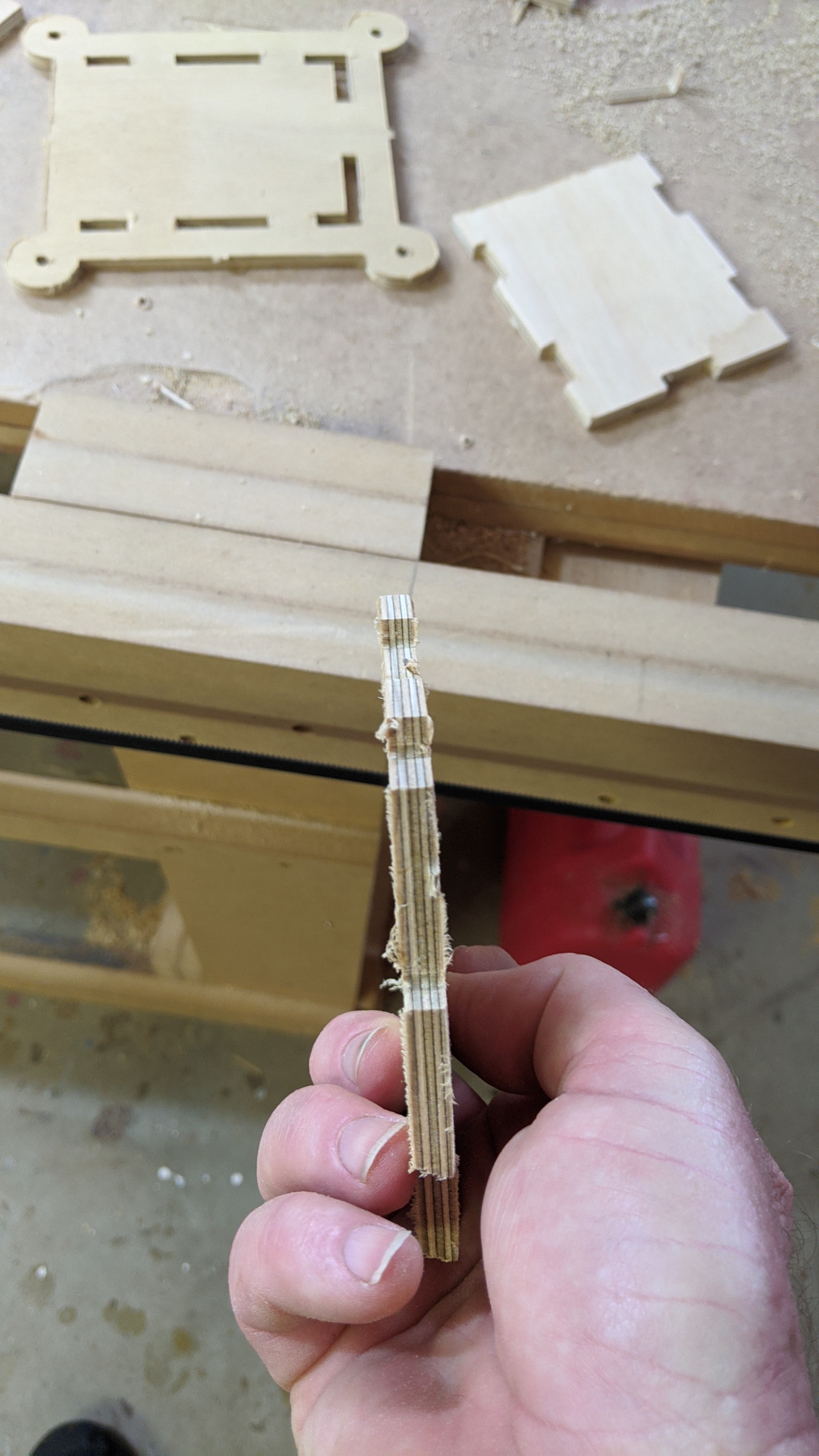
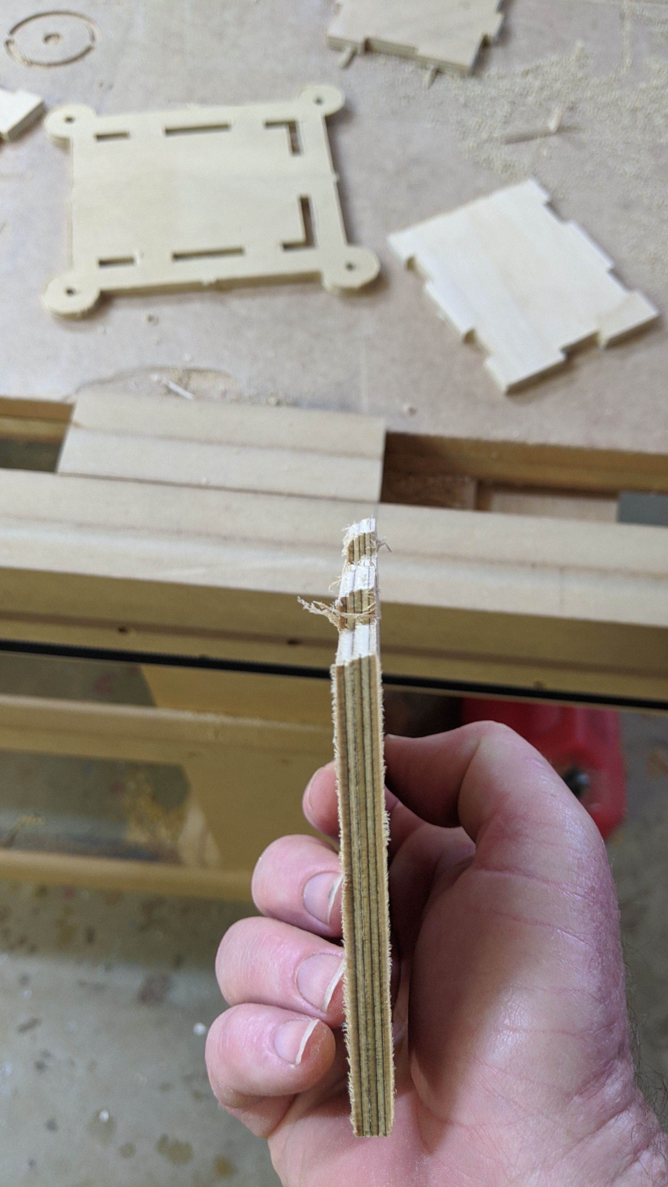
Here is a photo of the offending piece.
It shows that 3 of the sides are nice and vertical but the one on the top of the photo is at about ? 70 deg to the horizontal.
Here is the Gcode for it.
FRONT FACE.gcode (16.8 KB)
It is a bit of whimsy I designed to screw to the wall of my Renault van to let me charge my bike lights and bike computer in the back as my bike lives in there.
Things you do when you are locked down.
What about the “top” of the tab on the right? is that also angled by your phantom 4th axis? Also, is it truly angled, or is it stepped? It almost looks like it’s skipping steps on the way “up”, causing the bottom of the cutting area to move “down”. You only see the “top” edge(s), because the endmill squares the “bottom” edges each pass. You can also check by verifying which side is more dimensionally accurate. The narrow top, or the wide bottom? (I’m guessing it’s the wide bottom)It appears that the angled edge of your piece came from the straight edge of your scrap, and vice-versa, reinforcing the theory that it’s slipping “down”.
Check your grub screws… 
Thanks mate. Will have a look at them. I reassembled it all last week after I buggered up the Y plates and had to redo them. (left some bearings out…).
I did them pretty tight but will double check.
What I don’t understand is 3 sides of one piece are good and the other is not… ie the top side of X axis is angled but the bottom is not. The others are all good. Reading what the G code says is beyond me.
I suspect some sort of hardware drama so will go and look at what you suggested over an ice cold frosty tonight after work.
Thanks mate.
R
If it was a 3D printer, you’d probably see the whole thing skewed over. One of the two angled edges is straight because the spindle is cutting the angled parts off. But each pass is moving progressively in one direction.
Sunday today, so I was thinking I might re cut the part and see how it looks. I am sure the neighbors won’t mind.
Rob
Me again.
Well I thought I would try a different approach to validate what I have done here. Clearly there is something I have not done properly. (got all the bearings in… counted them)…
So got a bit of 12mm pine, designed a paint stirrer in Fusion 360, generated the .dxf and created tool paths with Estlcam. Using 6.4mm down cut bit.
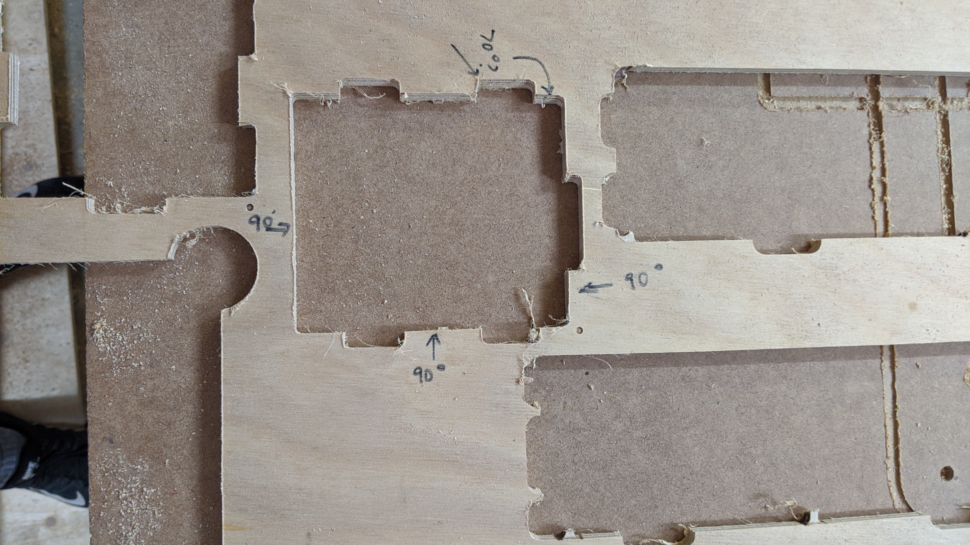
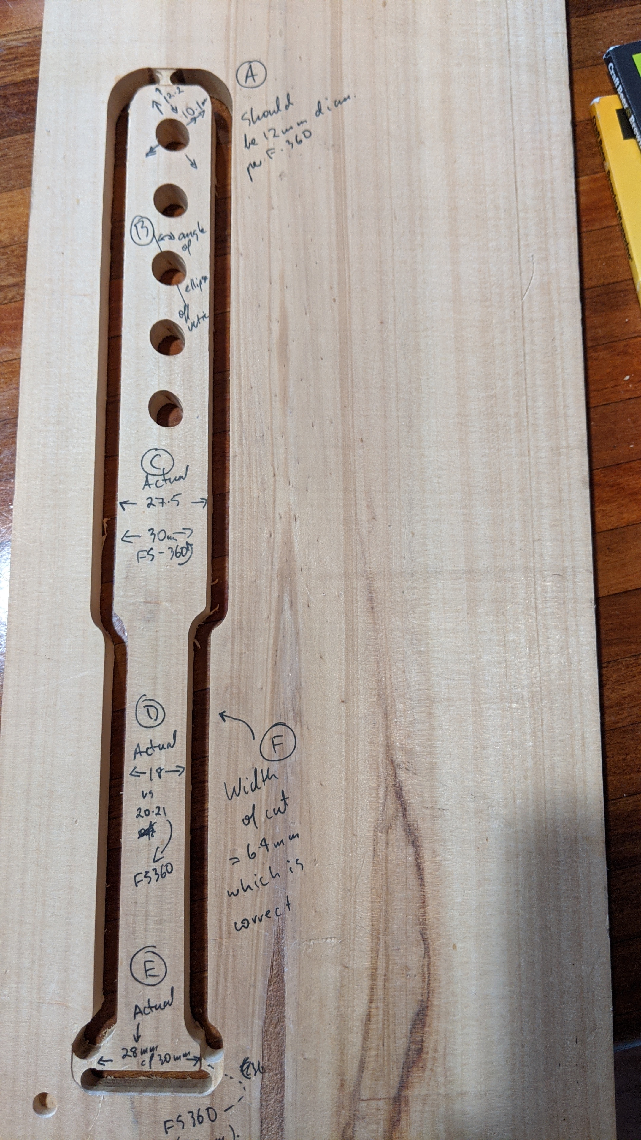
So… here is a photo of what I ended up with and have highlighted with these letters.
A… circles which should be 12mm in diam ended up elipses inclined at an angle to the Y axis of about 25-30 deg. Narrow axis is 10.1mm, long axis is 12.2mm
B. all of them are at the same angle to the Y
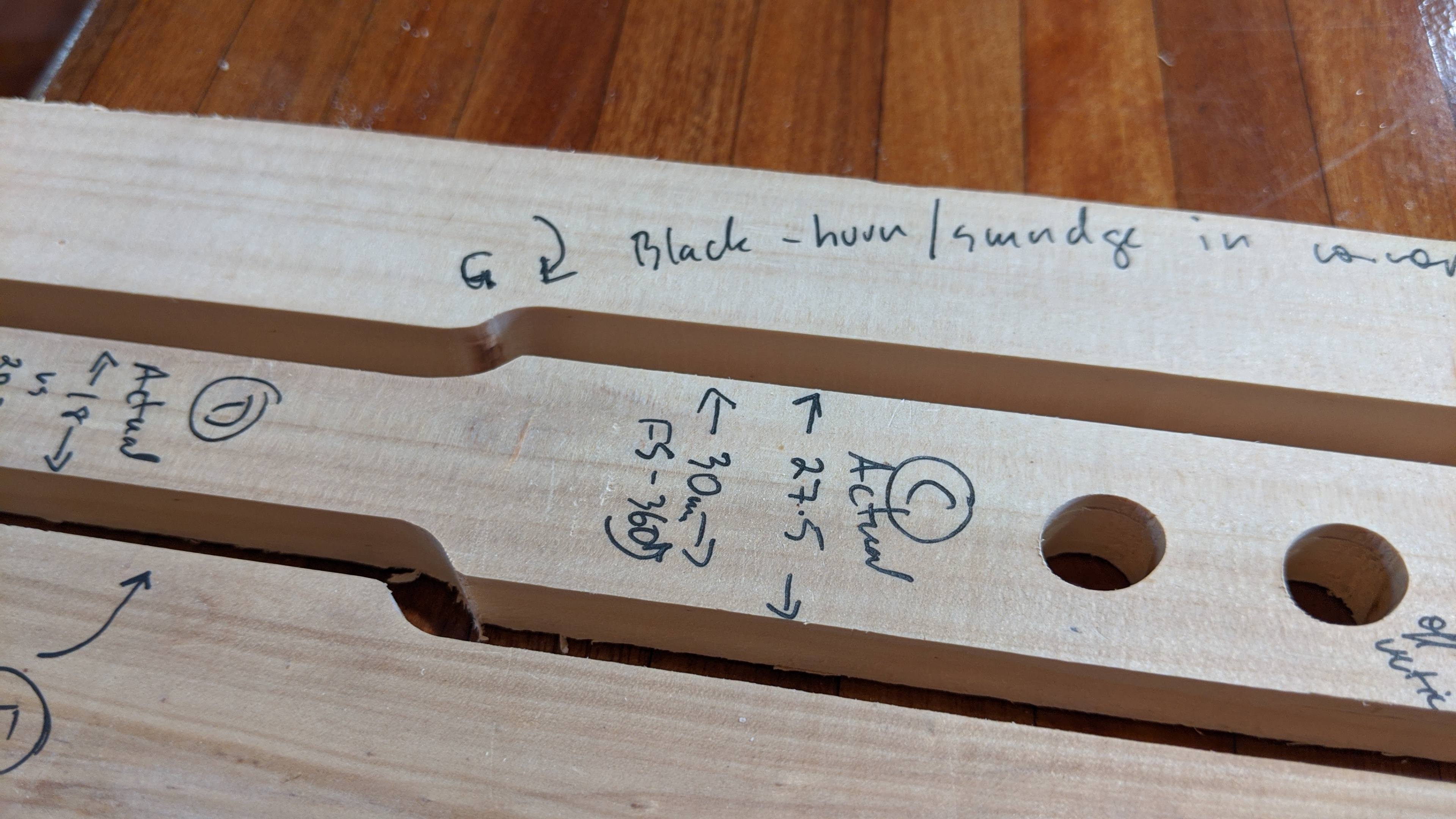
C. In FS 360 the designed width is 30mm but ended up 27.5mm
D. Actual width is 18 vs 20.21 in FS 360
E. End of the stick at the base should be 30mm but is only 28mm.
F. the width of the cut is 6.4mm
As it was going around the outside cut when the router got to point G it sort of changed sound and acted as if it was catching and it created a burn mark there which suggested to old Sherlock here that it was not maintaining the ideal track.
The overall length of the stick is actually 29.2 when it should be 29.3cm ie 1mm shorter in the Y axis.
What do you guys reckon I have got happening here?
Here are all the shots …
Puzzled old Rob
What depth per pass and speeds did you use?
Do you have a 1/8" bit? The 1/4" ones have more load on the machine.
The steppers are “open loop”. So if they can’t follow the track, they will skip steps. If they do, they won’t recover, because they didn’t know they skipped steps. To me, skipped steps sounds like grinding gears, because the motor jumps from one set of magnets to the next, like it is skipping a gear tooth. Skipped steps could be caused by errors in the electronics, wires, or if something is binding in the machine. It can also be caused by CAM that is too aggressive.
Flex is caused by something stretching or twisting of parts will bounce back, and takes some load. If you cut the same thing in HD foam, it won’t flex. If your build is flexing, it could be something loose, but it can also be the CAM just being too aggressive.
Backlash is caused by something like the grub screw on your pulley being loose. Before being able to apply any force, the motor has to move past the flat spot. If some of the bearings aren’t touch, and it can rock, that can cause backlash. A similar thing happens when the wheels don’t track. The backlash is mostly designed out of the LR, so if you have these big precision problems in foam, something is loose. Backlash requires almost no force to show up, so cutting in foam or with a pen will show backlash.
In general, posting some shots of the machine, including the two ends, the belts and zip ties, etc. Can help discover mechanical issues.
Exactly what I see when feed rate to high usualy ovals in direction of grain. Can also be break in time with zip ties streching a little. What strategies did you use for holes. Ppcket?
While skipped steps are a possibility, I think that’s unlikely to be the problem in this case. The errors look fairly consistent from hole to hole. I think @timonjkl is probably on the right track. i.e.:
How snug are the zip ties on the belts?
It’s already been mentioned, but the grub screws on the stepper pulleys are the number 1 cause of problems like this. There are 2 screws on the pulley. One should be snugged up on the flat on the stepper shaft, before tightening the other.
Pictures of the Lowrider might help. Is your Z raised high while cutting? That would aggravate any play or looseness in the build.
With a grub screw loose the error gets worse the closer to the loose one you get speed is more uniform don’t ask how I know but a lot of experience with both loctite is your friend. Also a good book or design computer at work station Flex in new machines works out quickly the zipties settle in fast. Watch for movement that you dont expect.
Down-cut? That could be causing issues if your chips aren’t clearing properly, especially if you’re being aggressive with your CAM. And the 1/4" / 6.4mm bit doesn’t help.
I was using a 6.4m 1/4 inch bit. ie the standard chuck in the DeWalt router. I have ordered some smaller ones from the webstore about 4 days ago and I did wonder why they were all 1/8.
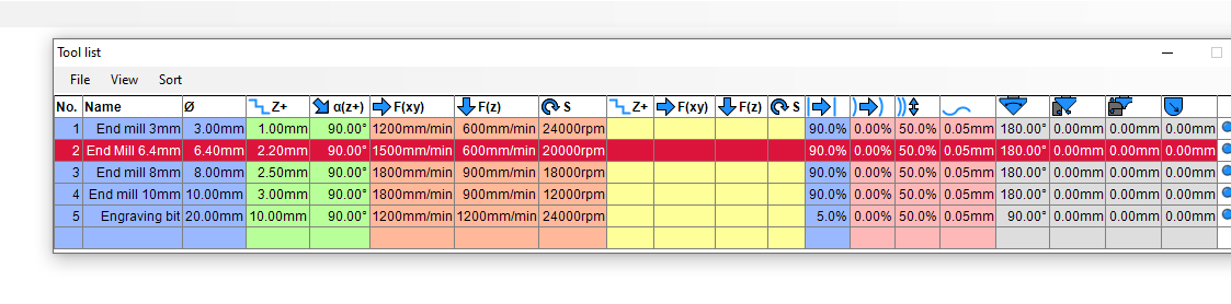
Here are my settings that have been working up until now.
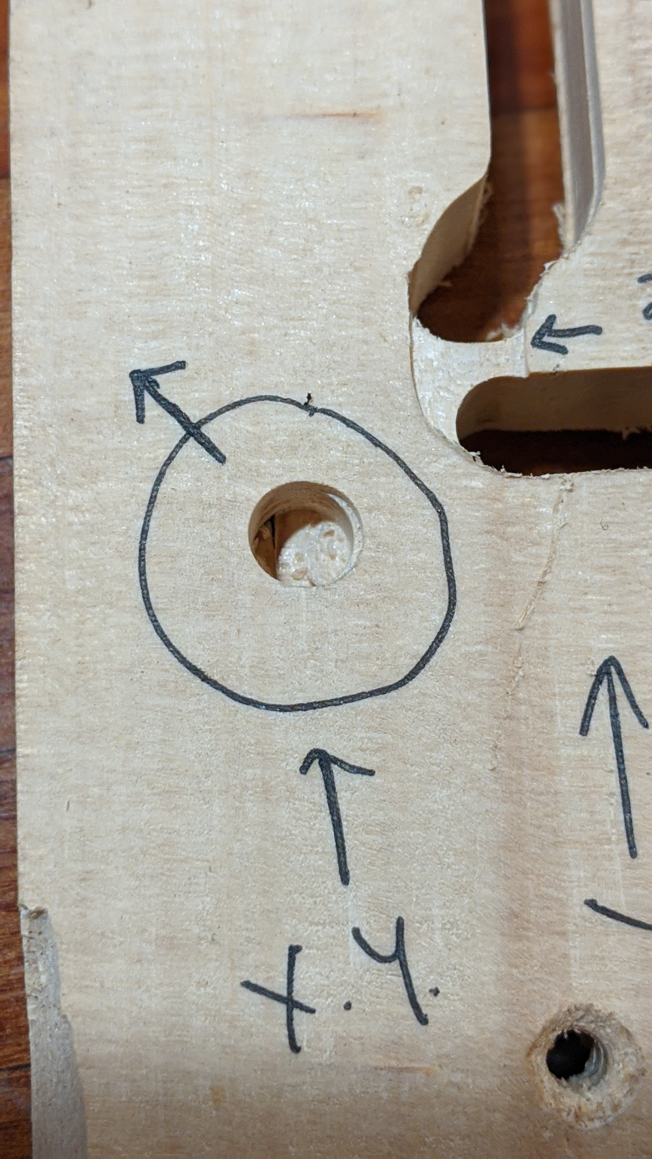
I also have here a photo from before and after of the job. ie did the X,Y reset and it left a small hole in the wood. I then re drilled that same spot at the end when the machine went back to the original XY but deeper.
Here is that photo.
It shows the deeper final hole is very very slightly to the same ‘direction’ as the ellipses that were to be circles ie 30 deg off the Y axis. (does that make sense?) ie it is pretty close but out a bit.
Just went and took more photos and a video that may help you.
Here is my Estlecam file and my Gcode too if that helps.
MIXING STICK.gcode (25.9 KB)
MIXING STICK.zip (24.1 KB)
Just as an internal part … figured with the 6.4mm bit it would not need to pocket.
What do you mean mate?
No if anything the Z was close to the bottom as I cut this one. Maybe that is part of it. It was too low? Could put a spacer underneath and redo it once everyone wakes up.
Will tighten and check them.
1500mm/min seems pretty fast to me, especially with 1/4" bit. I would drop that down to about 8mm/s or 480mm/min. If that goes fine, the go deeper instead of faster.
Those belts are also too loose, IMO. In that video it seems pretty clear to me.
The 2.5mm space you saw it move back and forth from that gap was my first thought. The machine should track straight and not have a problem, but if you have a high load, or something is out of line, then these can slide side to side. I installed some 3/4"x3/4" tracks next to my wheels to keep them tracking straight on my build. I think you should be able to see that changing if that is the problem.