I finally got some time to work on this project again. I’ve never got anything to cut on my MPCNC. I’m still trying to understand the process so let me explain what I’m trying to do.
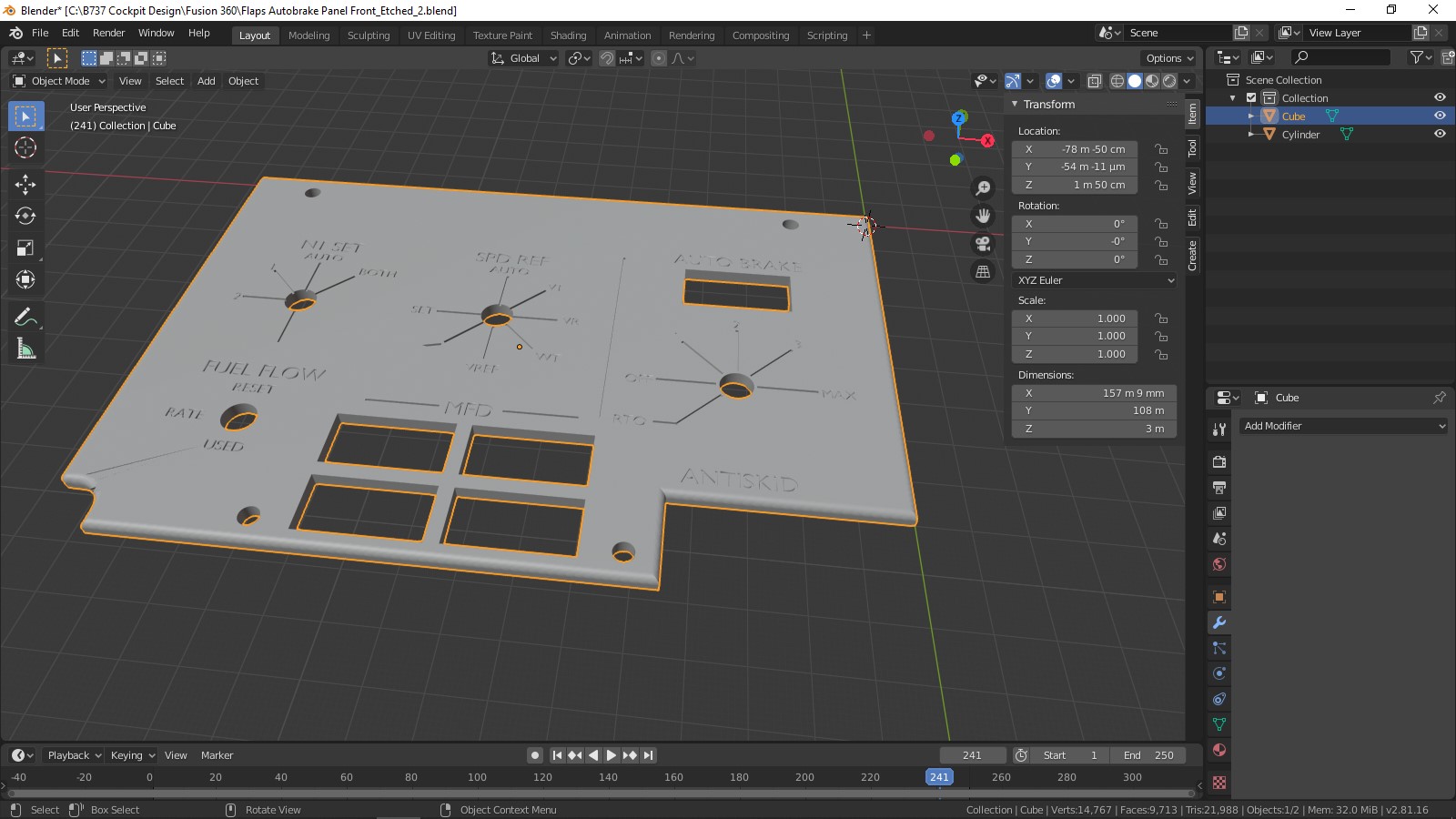
I created this panel in Blender that I want to cut and etch. It is x=157.9mm, y=108mm, z=3mm.
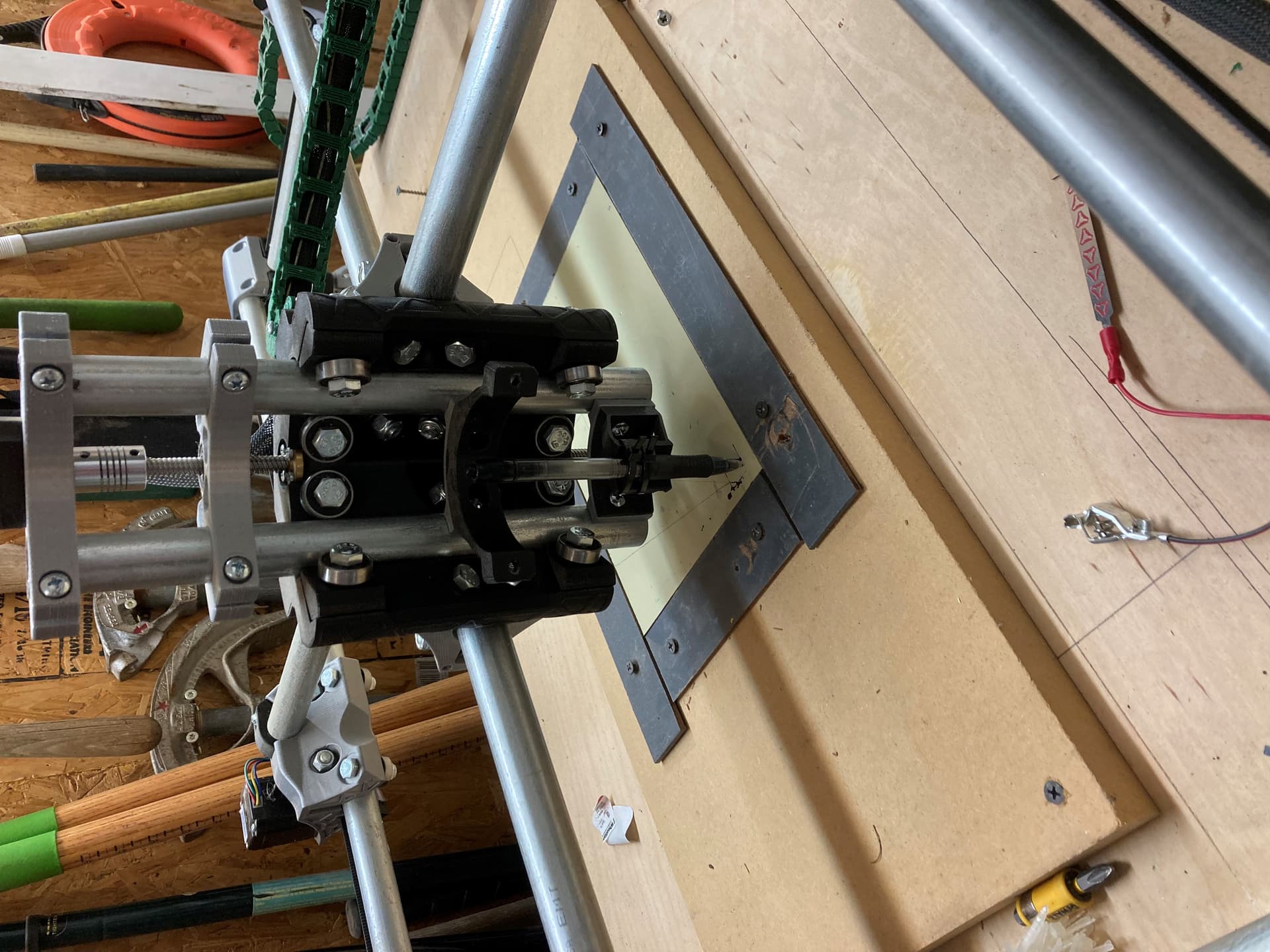
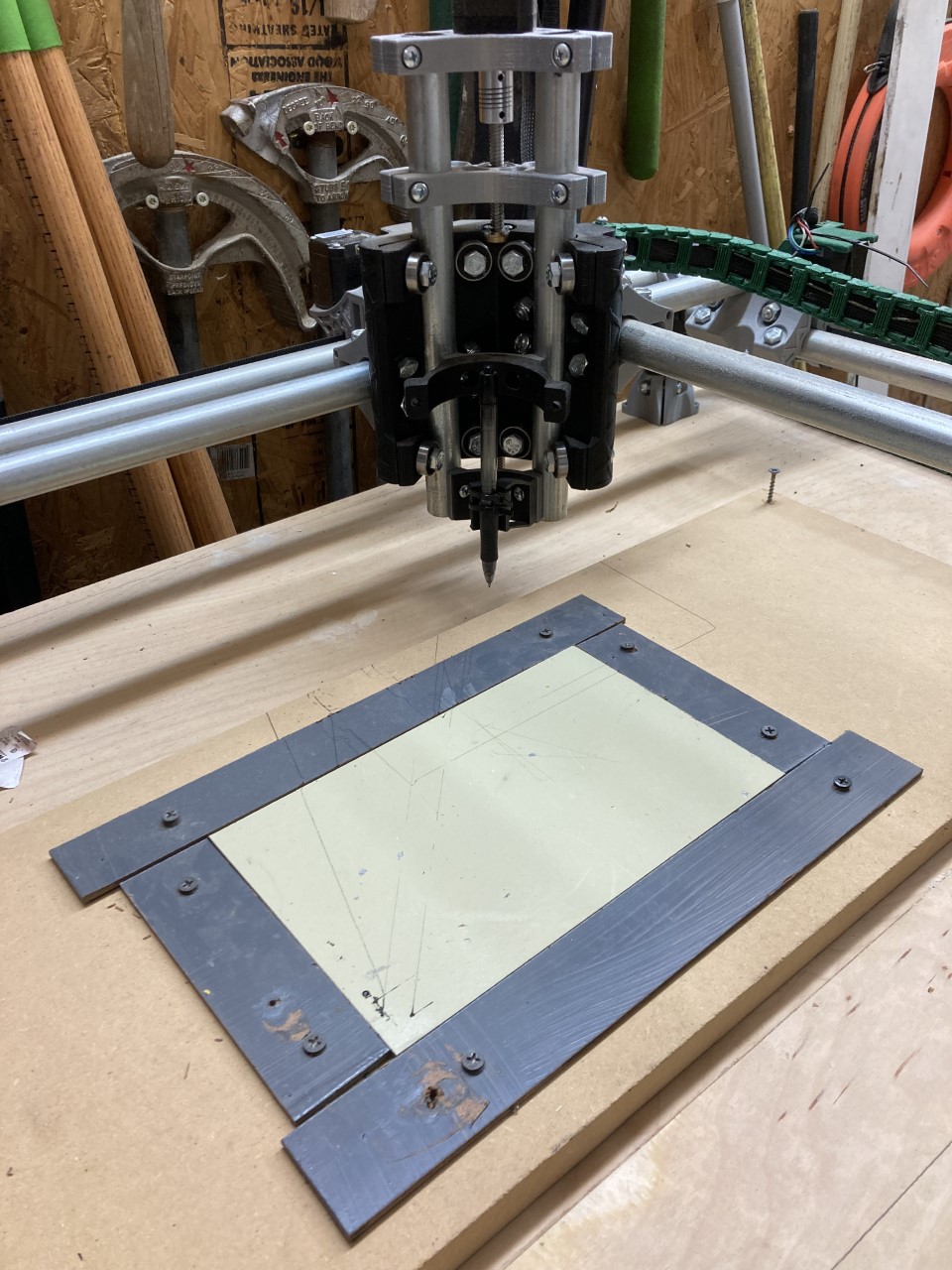
I exported it as an .stl, opened it in Repetier-Host and sliced it with Cura. I want the bottom left corner of the panel to be at the position on my cnc shown in the picture so I want the router to start there. I’m just drawing it for now.
I try repositioning the panel in Blender but it doesn’t seem to make any difference. I don’t understand how gcode sets the actual position of the object. I’ve tried moving my endstops to compensate for the difference but the router still moves way off from the position where my panel should be. I know I’m misunderstanding something but I can’t figure out what.
Alex is right, Cura is for additive manufacturing and CAM like Estlcam is for subtractive. Even just etching, or drawing the lines on your model is subtractive (even if you are just using a pen). Estlcam won’t do what you want with an stl though. You should make a sketch on the face you want to machine, and then add in the features you want to tool to follow. Export that sketch as a DXF and open that in estlcam.
The short answer is you need to set the origin when your pen is where you want the origin. I use G92 X0 Y0 Z0. I use a macro or just type it into the send gcode box. But you can also add it to the top of your gcode file.
And, if you want to just check out your machine to make sure it is working properly, start with the premade gcode file here: test crown. That gcode has been used thousands of times and has the G92 at the top. If you start it with your pen in the lower left, touching the paper, it should draw the whole crown and you can focus on learning CAM.
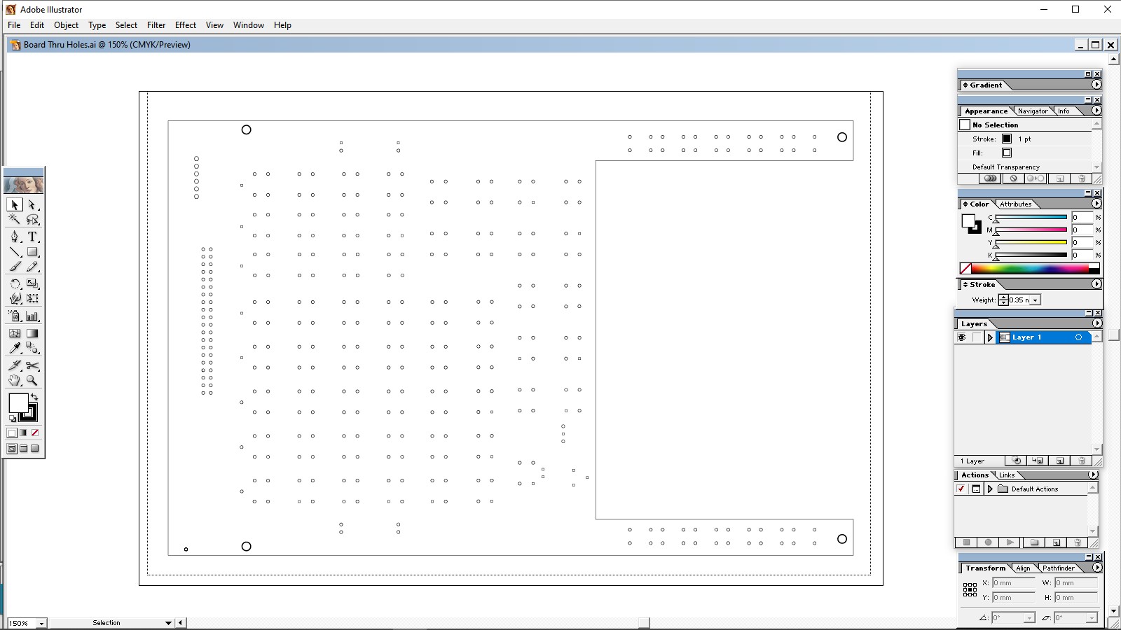
I’m really tired of struggling with Estlcam and Repetier Host. Sometimes when I import a dxf to Estlcam only part of my object loads. I’m trying to rout circuit boards on a copper clad board. Is there an all-in-one payware program where I can import a file from Adobe Illustrator and it does everything that Estlcam and Repetier-host do including simulating the routing?
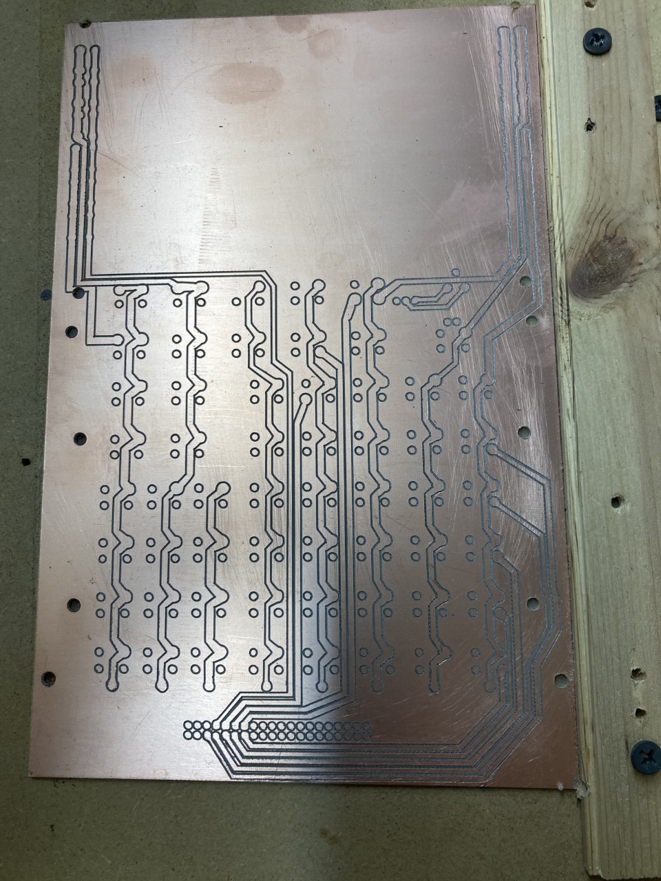
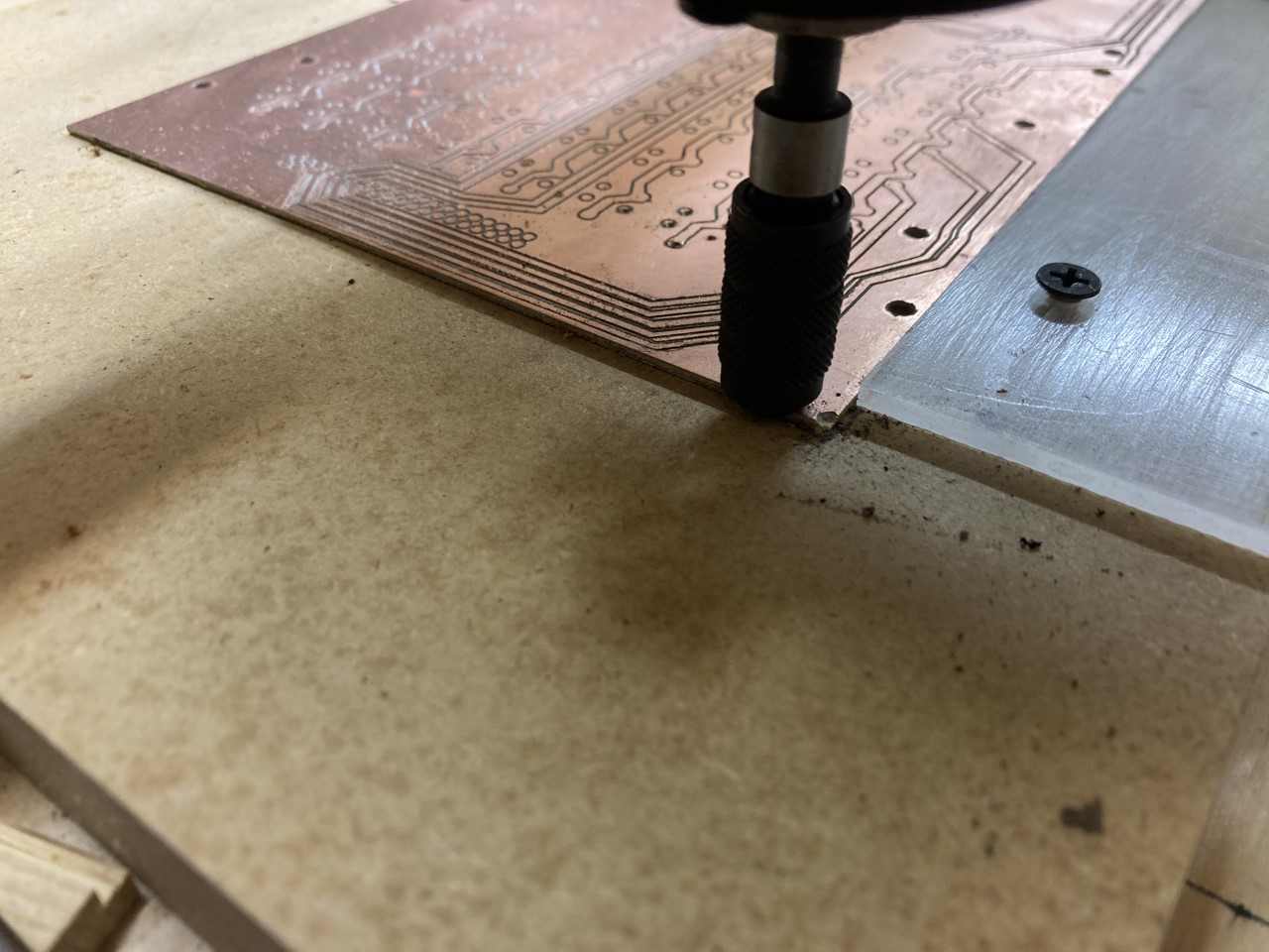
Well, I finally figured out what I was doing wrong with Estlcam and did my first cut, a pcb for my Southern engineered Flight Management Computer. This is just the front side. I’m hoping I got all my measurements right so the back side holes match the front side.
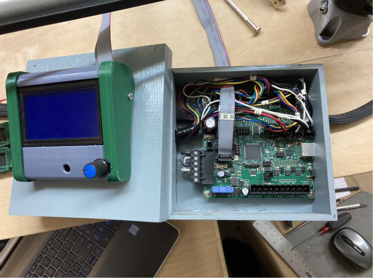
I also 3d printed the case for the lcd screen and built a box for the Rambo v1.4 board. I’m wondering if I made it too small. Will heat be an issue when I put the top cover on? All the cutting I have planned right now is very light, acrylic and Romark, nothing over 1/8" thick.
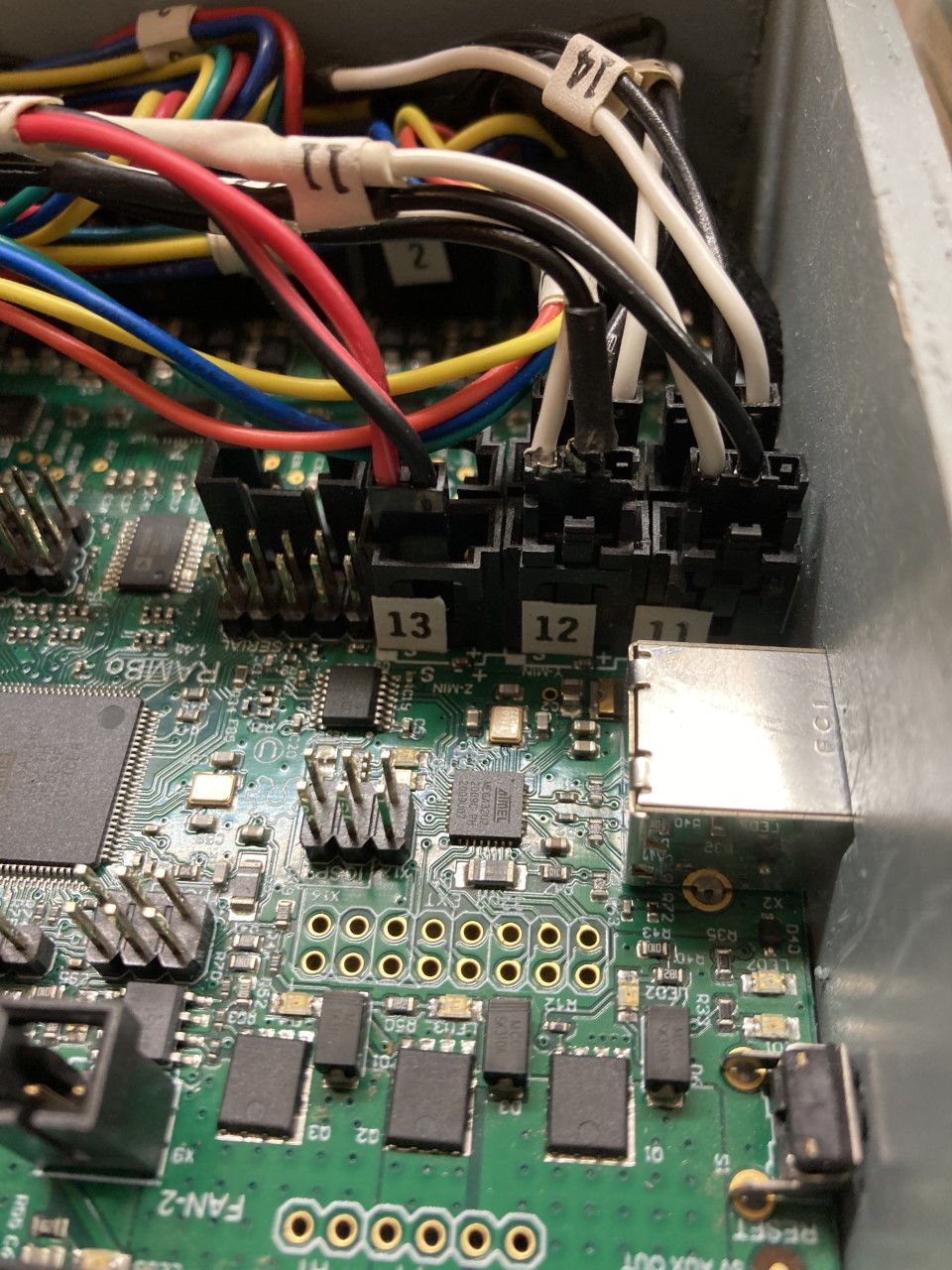
One more thing. I had to extend the end stop wires and I ordered some new crimp pins for the Header Connectors where the wires connect to the Rambo board from a company called Jameco but they didn’t quite lock in to the Header Connectorss and I’m having issues with bad connections. Apparently they don’t carry the right ones for those connectors. Can I order some crimp pins from V1 Engineering or can you point me to a company where I can order some?
I have some spares around here some where if you only need a few, if you need more I am pretty sure ultimachine has the part numbers listed for easy ordering on digi or mouser.
I checked ultimachine for the connector pins but they were sold out. The part number they listed was MPN 2226TG and I checked Digikey, Mouser and Jameco and none of them had that part #. I need at least 10.
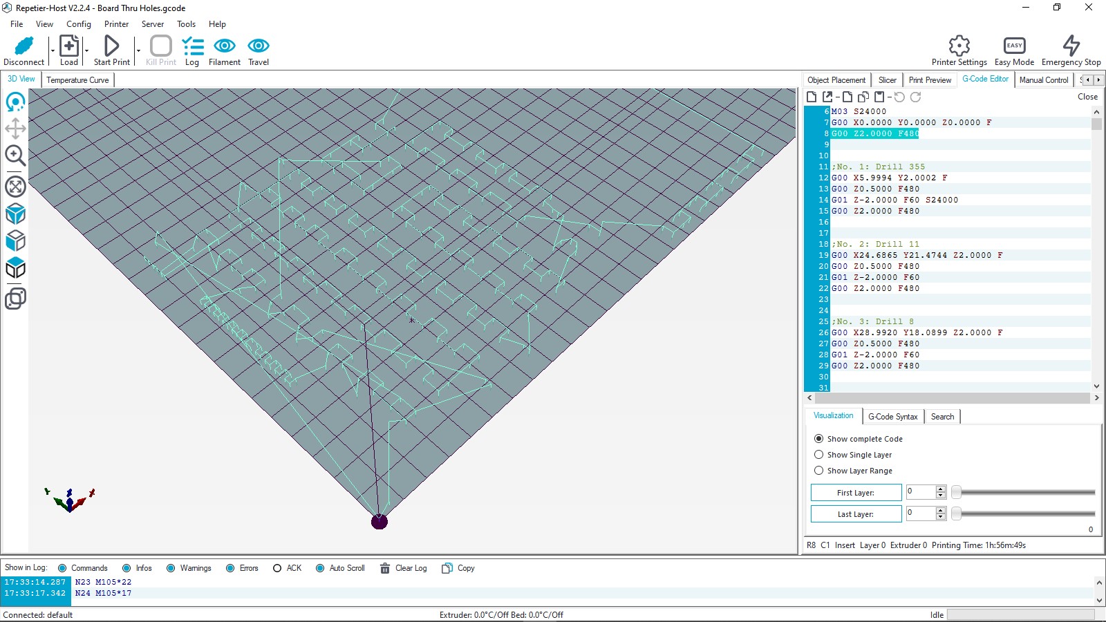
Today I attempted to drill the holes in my circuit board. I checked the distance from xy0 to ;No. 3: Drill 8 in my gcode and it was G00 X28.9920 Y18.0899 so I adjusted my end stops so they would be approximately X=29, Y=18 to that position. When I started my cut in Repetier Host the bit buried itself in the first hole even though I zeroed the Z axis high enough that it shouldn’t have penetrated the board. I just wanted to make sure it would cut the holes in the right place. I’m not sure why this happened.
I ran the code for the touch plate:
G28 Z
G92 Z0.5
G0 Z5 F480
when I cut the circuit board traces and it worked fine. I wanted to run this gcode just barely above the board first to make sure the holes would line up with the traces. I can’t really be more than .2mm off.
The F with nothing after it was generated by Estlcam, I didn’t change anything in the gcode.
Just one more question. What code do I insert and where so that the bit follows the path but stays 1mm above the board. I want to make sure it is drilling all the holes in the right place before I actually drill them. Or, when I generate the gcode in Estlcam, when it asks what depth I want my cut could I just put -1mm?