My only experience with firmware is loading it on the board. What program should I use to make the changes. I have a purpose for the p2 fan pins so if I modified fan 1 to #define FAN1_PIN 45 that should do it?
Any text editor can modify the file, or if you are using PlatformIO to compile and upload the firmware, then Microsoft Code is a good choice to modify the file. The file to modify is Marlin/src/pins/Rambo/pins_Rambo.h in in the source files that you have for the Marlin firmware. You might also wait a bit for feedback from @vicious1. It is possible that his recent laser work already has a 5V pin defined and/or he uses some other method besides fan control to control the laser. If so, he can give you a bit more information on how to download the daily build.
And yes, you can use one of the other two fan pin #defines.
He said something about the nightly having it enabled but I’m not entirely sure what that means.
Also! Thanks for all the helpful input!
I’m pretty sure I have successfully changed the firmware. Unfortunately it’s time to go to work. So I will load it on the board in the morning when I get home or something.
The Nightly firmware already has the 5V pin enabled as well as all the M3 options that seem to work best. might want to look through my “Lasers...revisted” thread real quick to get some specs.
I am finally getting back to this laser stuff and I’m trying to make a make the the change to firmware. I changed the #define FAN_PIN and FAN1_PIN to 45 but they both give me the same error in the sanitycheck.h
( #error “SPINDLE_LASER_PWM_PIN conflicts with fan1_pin.” 3107, 8
It says the same thing for both FAN1 & FAN if i swap them
I noticed an update to the firmware is it possible I’m trying to change firmware that has already been updated?
If you are using the latest firmware, then yes it is likely that you have a conflict. You are beyond my understanding of the laser at this point, especially since I don’t have one. I just have a bit of info since I preparing to install one in the near future. You have three choices:
- Assign pin 44 or 46 instead of pin 45 to your FAN_PIN or FAN1_PIN.
- Don’t do anything and figure out how to trigger the SPINDLE_LASER_PWM_PIN in your generated g-code (probably the right long-term choice)
- Reassign the SPINDLE_LASER_PWN_PIN to something other than 45 to remove the conflict (like 46 or 44).
I will attempt option 2
I flashed my board with new firmware, hooked up the laser and at first it was always on. I then had control of it for a moment and now it’s not doing anything
If you take a look at lasers “revisited link” that Ryan provides above, you will see a g-code file associated with the first post. As a test, you could just take the first several dozen lines of g-code from this file and run it on your machine. If you look at the code, it is controlling the laser using the ‘S’ parameter on all the G1 g-code commands. You will see something like this:
G1 X26.22 S52
The ‘S’ parameter with a spindle is used to control the spindle speed. With a laser, it controls the laser output. I believe the values run from 0 for no laser to 255 for the laser on full. So the value of 52 for the ‘S’ parameter should turn the laser on about 1/5 power. I’d be surprised if the laser output is linear, so you likely have to run some tests to figure out laser output for various values.
Since I’ve not yet played with outputting any laser code, I don’t know what needs to happen to get the various post processors to output the ‘S’ parameter in this way, nor how to author the various levels of laser output in the CAD/CAM software.
Note that the laser stuff appeared in the latest version of the V1 firmware, so you still need to flash it to your board.
1 Like
Thanks for the assistance! I’ve got it flashed. I got lightburn running but not matter what settings I change i can not for the life of me get the laser to fire.
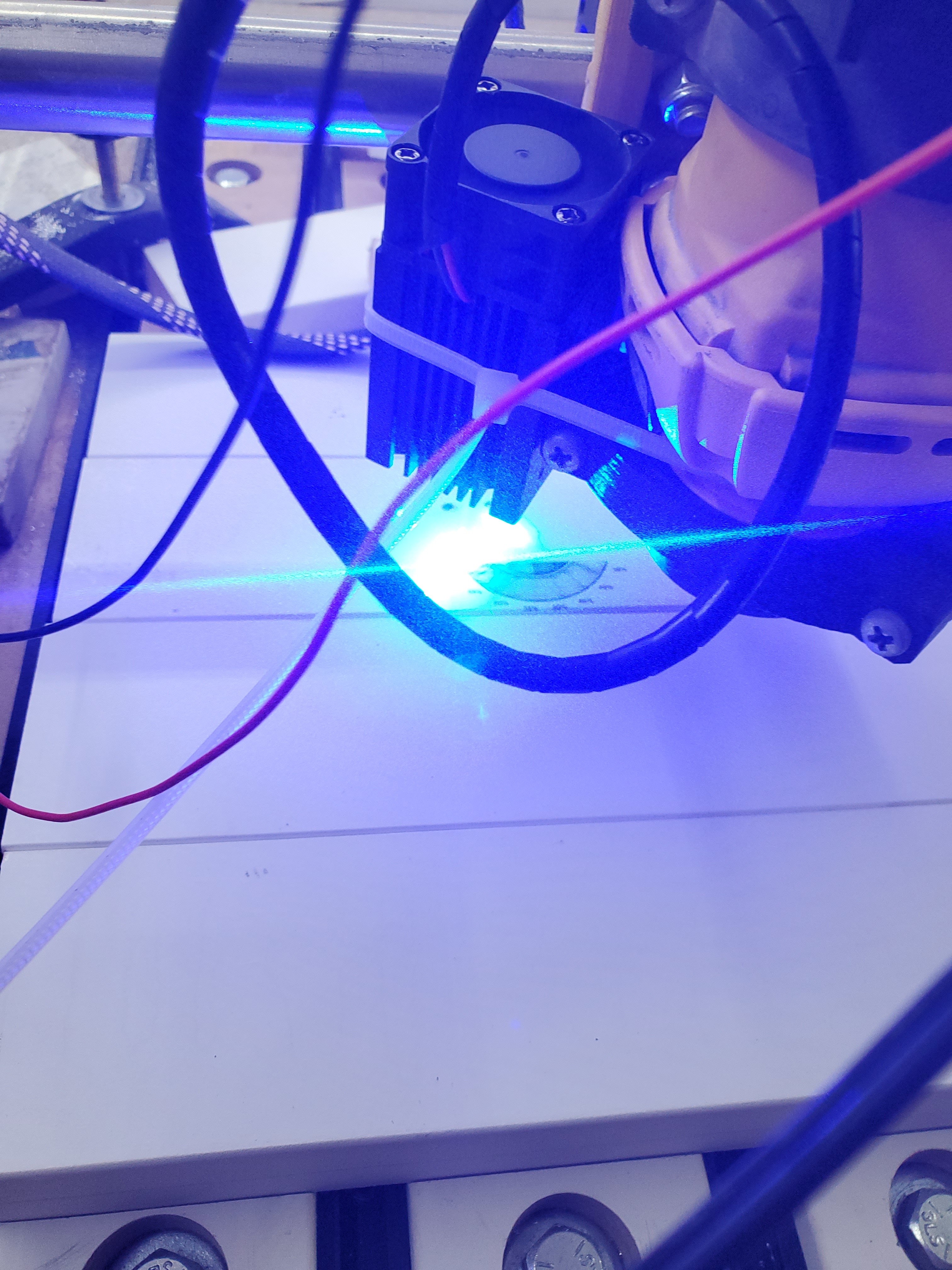
I know the laser works it has this switch.
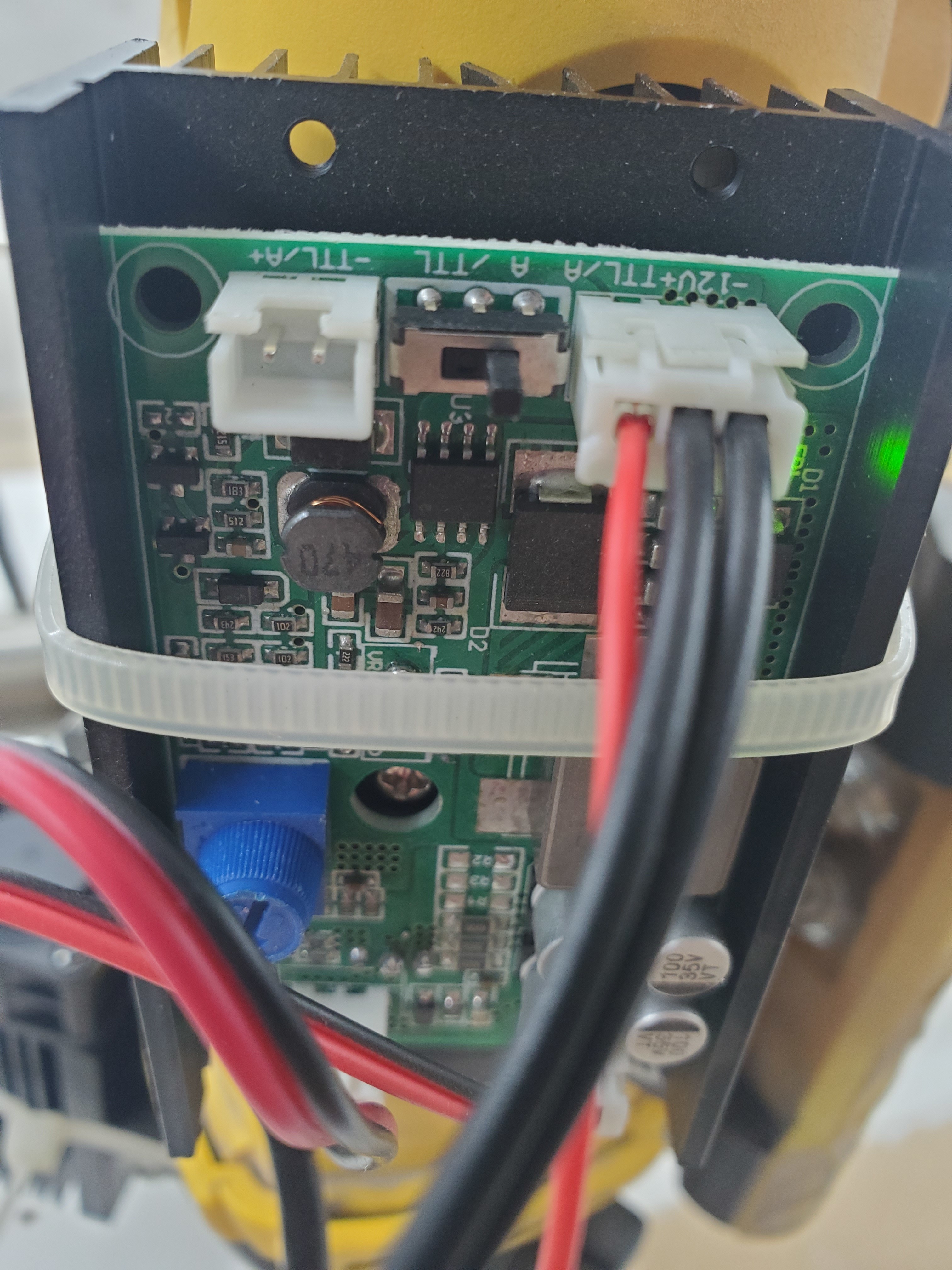
Switch to left always on. Switch to right and it’s off. On the right side I was able to send a code in RH and it fired but then stopped. So I loaded lightburn for the first and I have been playing with settings for 2hrs still no luck.

First if you send the top few dozen lines of Ryans g-code file, does anything happen? Second, as a test, you should be able to move the signal line from the laser to a +5 pin to test turning the laser on. Third, if you post the g-code file that comes out of LightBurn, I might be able to spot something. Again, all my knowledge is theory. If you cannot figure it out, maybe it is time to open a new Topic.
First, you need to make sure your laser is working. You should be able to plug the laser control line into a +5V pin. You will find three 5V pins in the red rectangle in the image I posted above. Note that if this works, the laser will always be on if the control board is on, so take precautions. If this doesn’t work, you have some hardware issue(s) to figure out. As for the last g-code you posted, it is identical to Ryan’s g-code in that the g-code is controlling the laser using the ‘S’ parameter in G1 commands.
Edit: This is a shot in the dark, and you might want to get a second opinion. If the 5V pin does not work, and if you are using a separate power supply for the laser, you may need to tie the ground pin of the second power source to a ground pin on the control board to get things to work.
I tried the positive and nothing so it appears I indeed have a hardware issue.
I will take a step back and see if anyone else may have a solution.
Again, if you are powering the laser from a separate power supply, I’ll bet you need to tie the ground of that other power supply to the ground of the control board.
2 Likes
I’m hesitant because this is $300 in electronics. I will give it a try.