Like this part?
1 Like
That is what I was thinking, to do something like that to keep the cooling air from overwhelming the dust collection, but be out of the way of the laser.
The part as is is good with the router.
I did make that other part which works with the laser, clipping to the side of the router, but I decided that I didn’t really like that approach after all. It works, but can be bumped while in operation, so something more solid is desireable.
I also realized that I never levelled the X screws all the way, but G34 should be usable… or the RRF equivalent, anyway. I already have the script set up.
I was also thinking I could set up a G29 mesh level map. At 100mm increments, its 140 points with my current config. That should be helpful in depth cutting.
Do you want the makita or the dewalt as the base file, or just the blank mount?
I could use the Makita if you don’t mind.
2 Likes
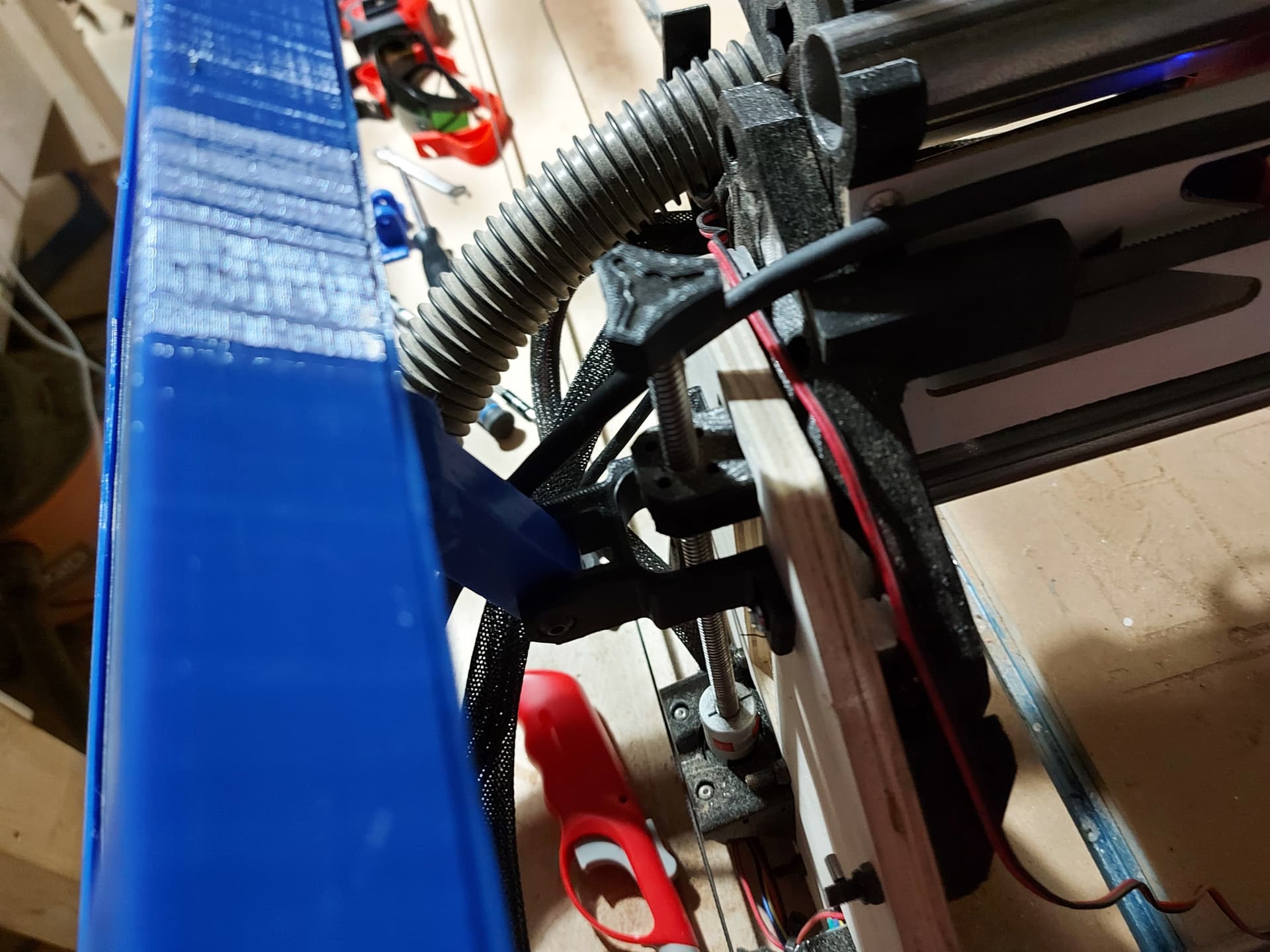
The aluminum case of my laser is touching the top of the upper dust shoe. The air assist still sticks down farther than the bottom of the core.
I have the DeWalt version. I just don’t know the difference. Is the Makita shorter?
I haven’t got rhe DeWalt pne, so can’t say for sure, but the @dkj4linux air assist nozzle is at least 1cm higher than the bottom of the core…
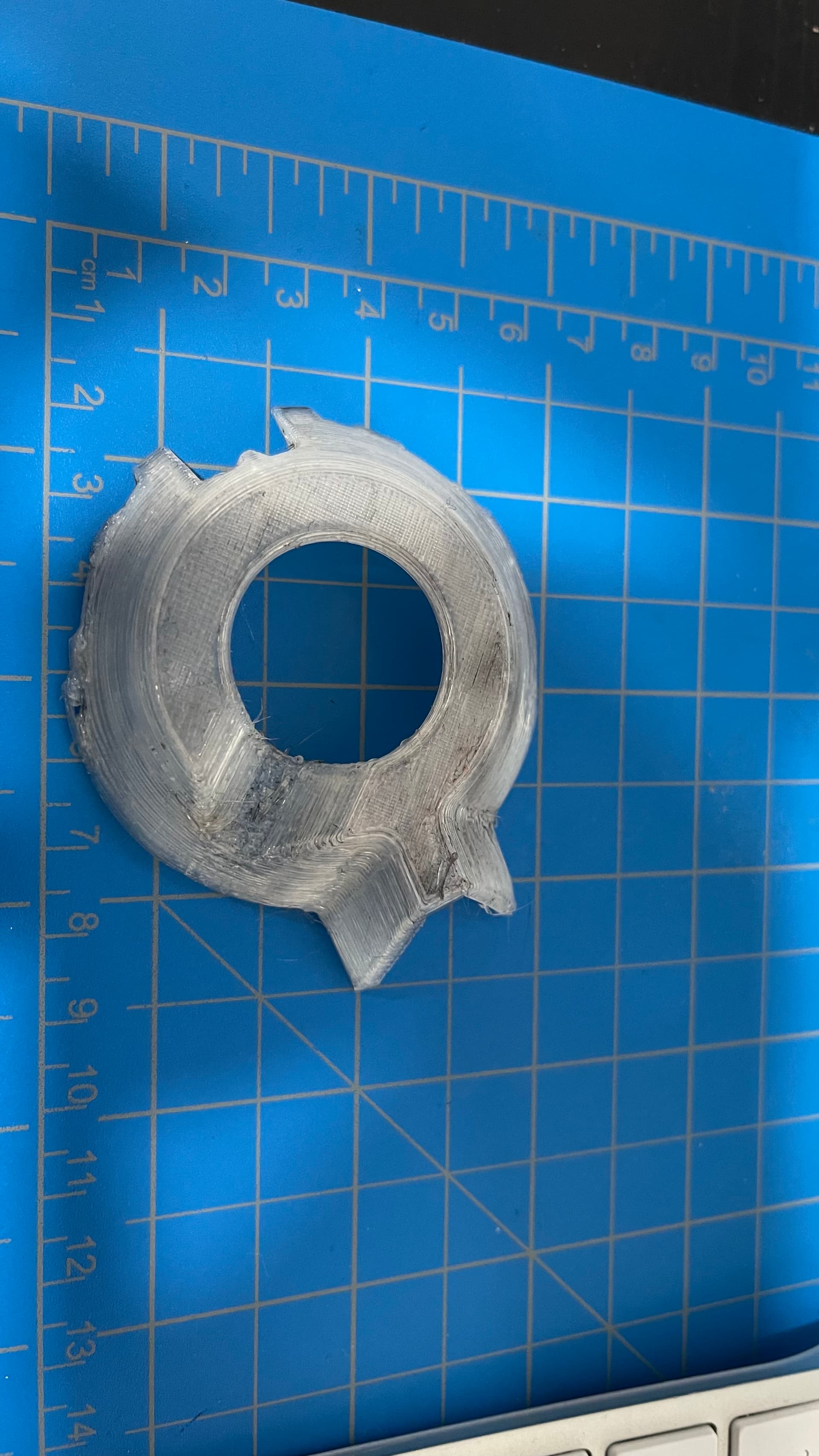
But not anymore.
It’s a little flimsy feeling, I think I need to reinforce it a bit. There is some room to make the retaining lip thicker, so I’ll try to do that, maybe make the inner wall a bit taller.
2 Likes
Sweet thing!!!
You have 2 forces helping you, the air flow from the router pushing it down and the vacuum also pushing it out.
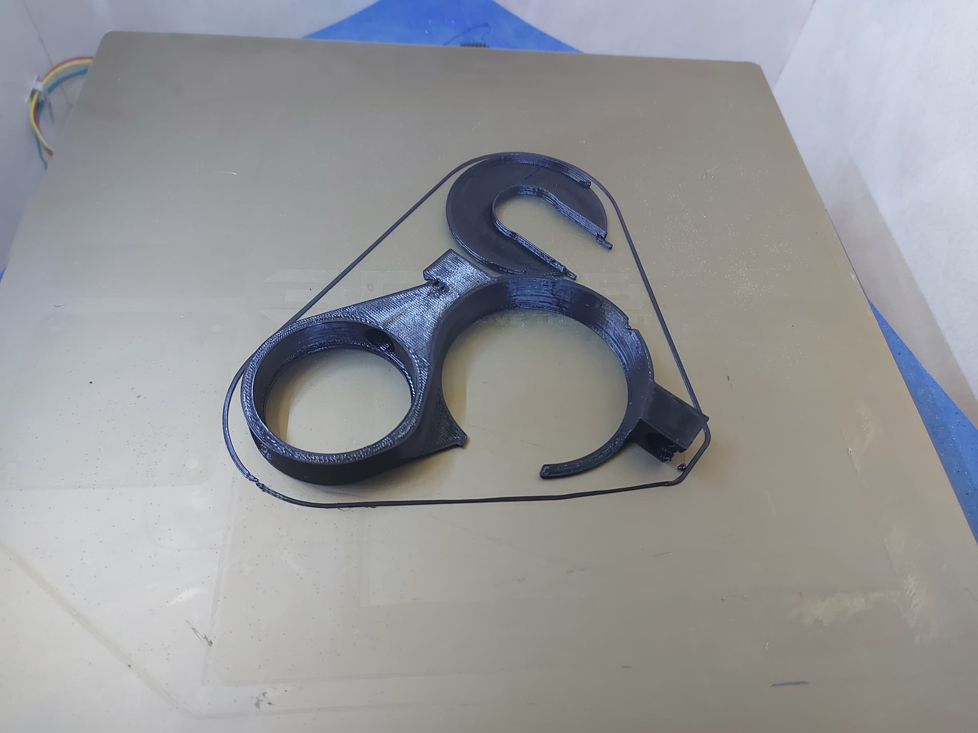
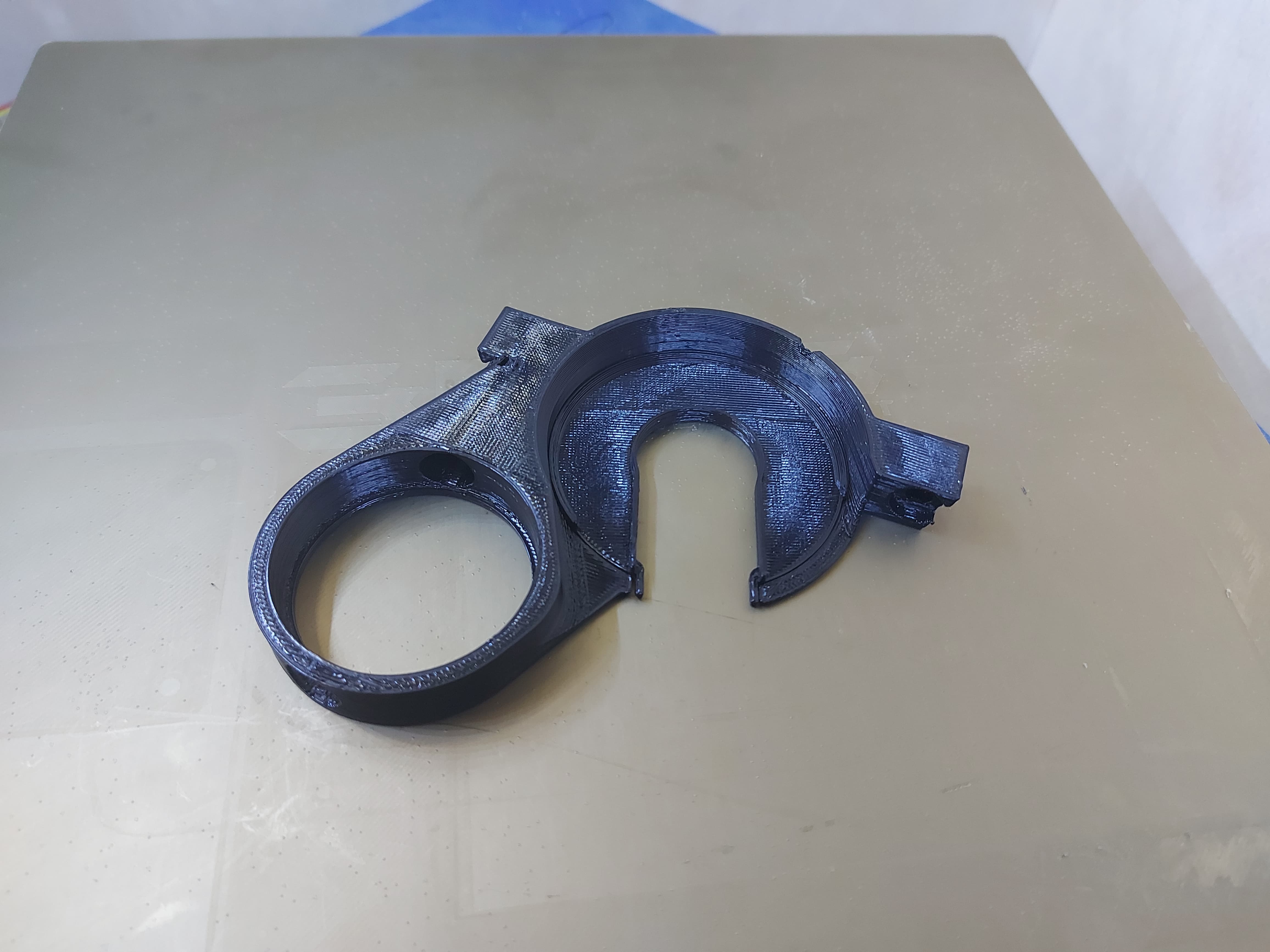
I think it will work just fine. I will try to do the same for the Makita. And I will also try to add a skirt to the bottom (detachable) part of the vacuum shoot.
The way it is works great for MDF and plywood, but when cutting acrylic, I had shavings going everywhere.
1 Like
… that is for the Makita…
Feel free to add them to printables or wherever.
That is a cool idea.
1 Like
Ops I miss read your post
Sorry !!! And thank you!
Bummer for the G34… RRF doesn’t like something. Well, Ill get it sussed. I want to try G29, but 140 probe points is going to take a while…
Whoa
1 Like
One more little step…
That 7" screen looks HOOGE though.
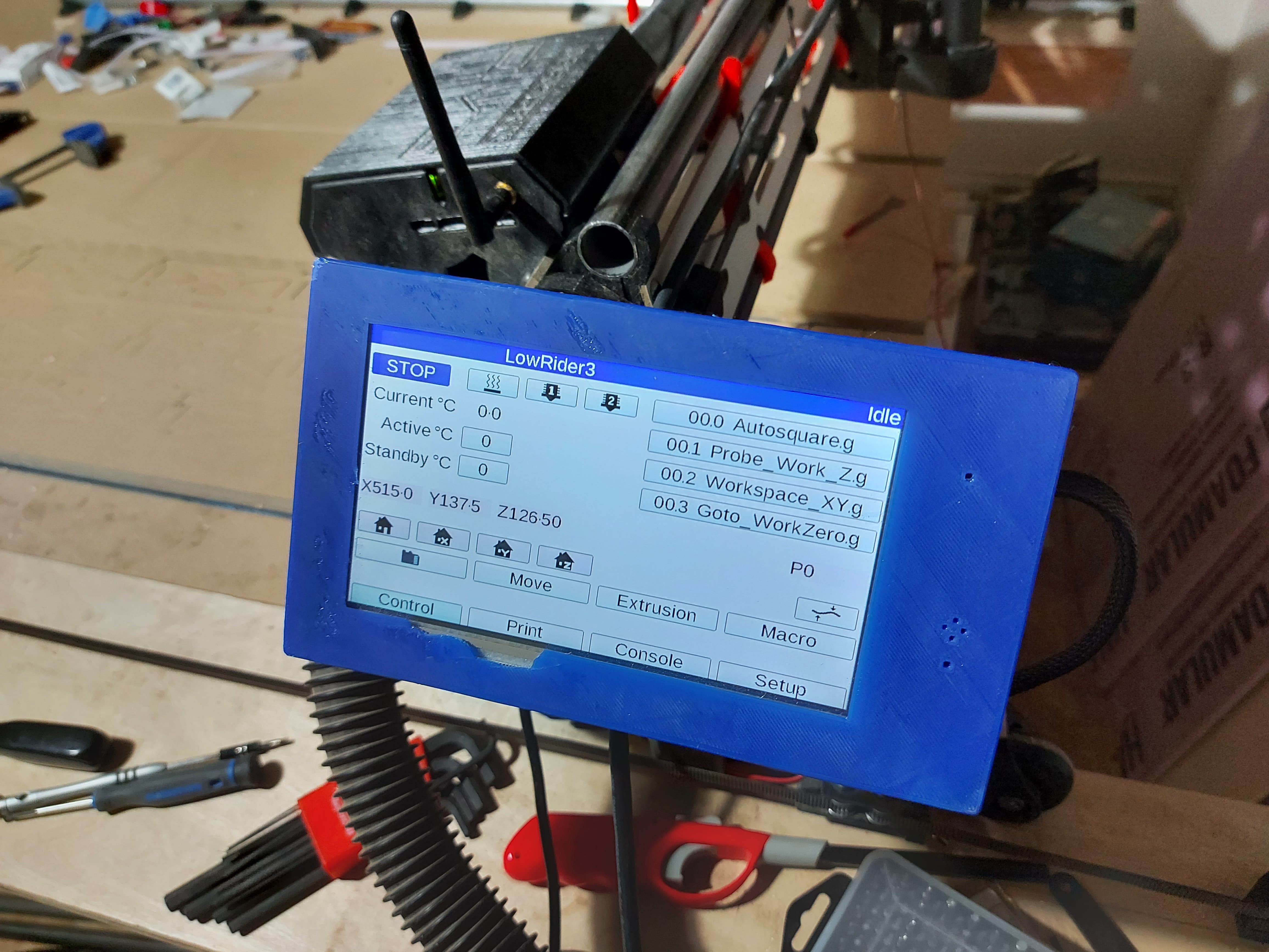
Looking at that 1" tube in the background, kinda wondering what the 1/2" conduit would look like… and thinking of my reusable aluminum straws. …
4 Likes
I think this is just about done.
I have some firmware issues to go through. For some reason, RRF doesn’t want to let me use the probe to auto-adjust my Z axis. Not sure if this is becsuse thr 2 Y drives or because CNC mode. It will report though that as it sits the rail side is 1.61mm higher than the wheel side. I don’t think I have enough adjustment in the Z stops to fix that in hardware. Kind of tempted to remix the Z stop with more adjustment on the one side. Or I can fix it in software…
I haven’t done an exhaustive check of square in the XY plane yet. Those will require software fixes to the Y endstops, too, unless I deem it acceptable strangsr things have happened. RRF should actually make those changes relatively easy. The biggest annoyance is making sure that I reset the axes back to normal when it’s all done.
One minor annoyance is that the 1/8" mills don’t quite reach the spoilboard in all locations. This obviously means that my table isn’t perfectly flat. Maybe building a new table should be on the agenda. A better, flatter torsion box wouldn’t be a bad thing. The trick would be to fit it in the build volume. Lower priority for now though.
You should have 2mm on each available to you, so one up and one down gives you a range of 4mm…I hope.
I’m still concerned about the bearing toe tapping. If it is not really far out heel to toe, it has to be beam twist. I can’t think of any easy way to measure that because any way you set it down will add some twist. I can only imagine if you tried to remove the belts, and balance it on some sort of small box in the beam you would see if your bearing toe is a lot higher than the wheel toe. I think that can be twisted out by hand. If not the strut plates would need to be loosend up a bit first.
This will need to be a step in the instructions if that is the case.
1 Like
I saw that, but this is where it’s sitting, looking like I need another 1.61mm of adjustment. I’m sure that it’s my table that’s weird. I had some issues with the LR2, but with much more adjustment available to my stop setup there, it didn’t show up this much.
Add that to the list of differences, I guess. The LR3 will show you more of your poor carpentry in table building.
1 Like
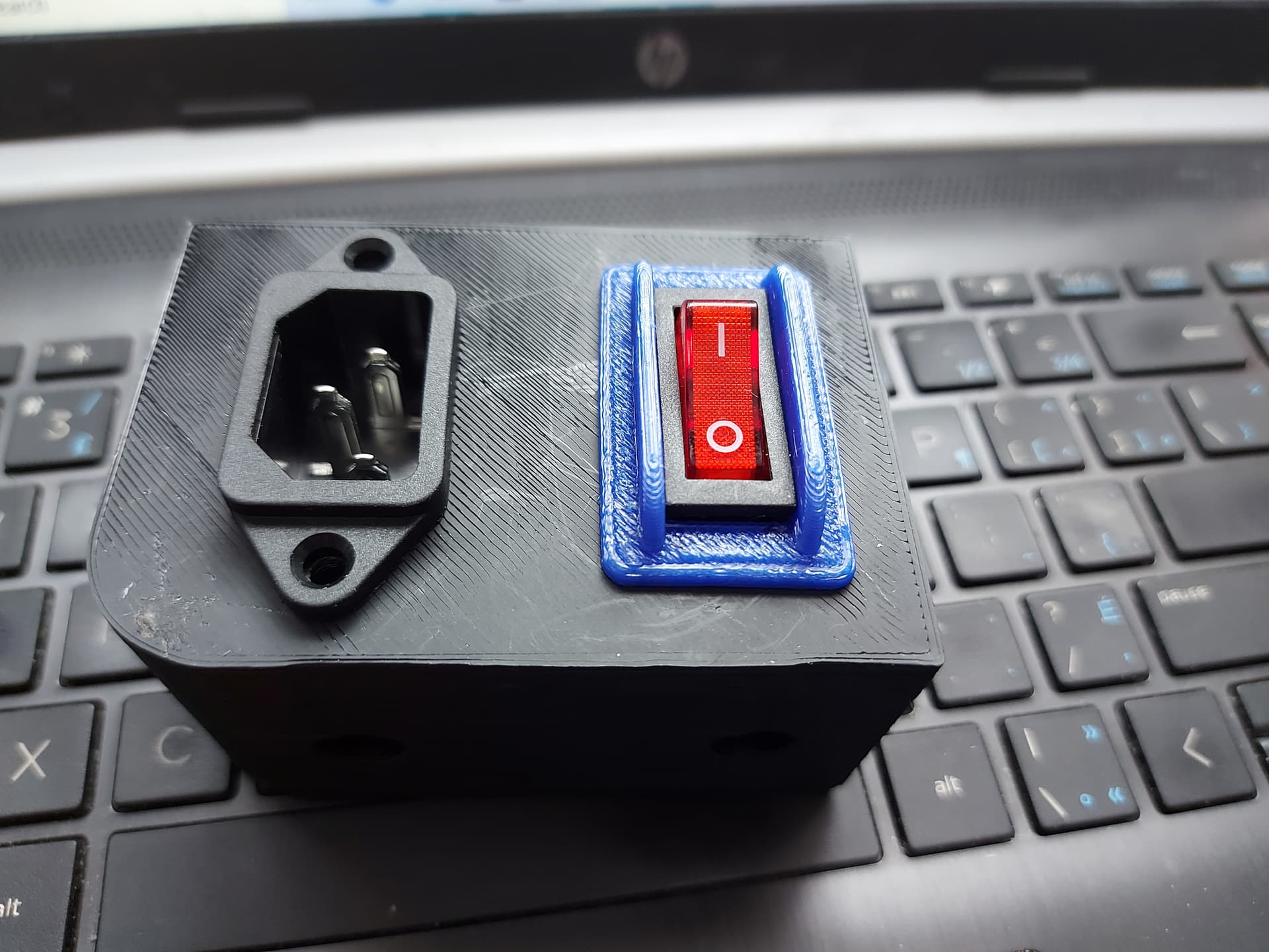
Finally getting started with some power management. This will be the master switch for the electronics. I will use a safety switch for the tool power.
I added the switch protector after seeing @jeffeb3 power box and thinking about not accidentally hitting it. It should maybe have those ribs stick out just a little further…
3 Likes
Well, my power management project went down the crapper big-time. My plans all went awry as soon as I tried to actually wire up stuff, so I’ll need to redesign.
The linear rails for my second Repeat printer are finally inbound, so I guess I better get moving on that project soon-like.
I got in a 12X24" sheet of 12mm acrylic too, which will (hopefully) end up being my new YZ plates, though I’m not unhappy with the plywood. I still haven’t decided if I want to do the single bearing wheels or stick with the skate wheels (Or a printed wheel to adjust the Z height)
Overall, I’m quite happy with the build. I have some of the updated parts to print and install still, but nothing that needs to be done to get excellent results.
1 Like
Wow, this past bit has been crazy busy.
With pandemic restrictions lifting, it seems that all of the past activities that have been on hold have hit all at once.
I am finally settling down to look at this, and I’ve got half done stuff all over. My power management is still a big freaking mess, and I’m overdue on the Repeat printer project.
Part of that was supply chain garbage, but I have the linear rails and the 20mm square tube (I am going with aluminum this time, and maybe swapping the other one over, the weight seems similar and the aluminum is smoother.)
I still can’t seem to find a good heated bed, but if it comes down to it, I will figure something put with parts I have. The cheap PCB bed that I have will do the job, I suppose.
I keep rethinking the power management. Analysis paralysis to the nth degree. Eventually I’ll just cut something and call it done. Nothing seems to be an easy fit for it all.
3 Likes
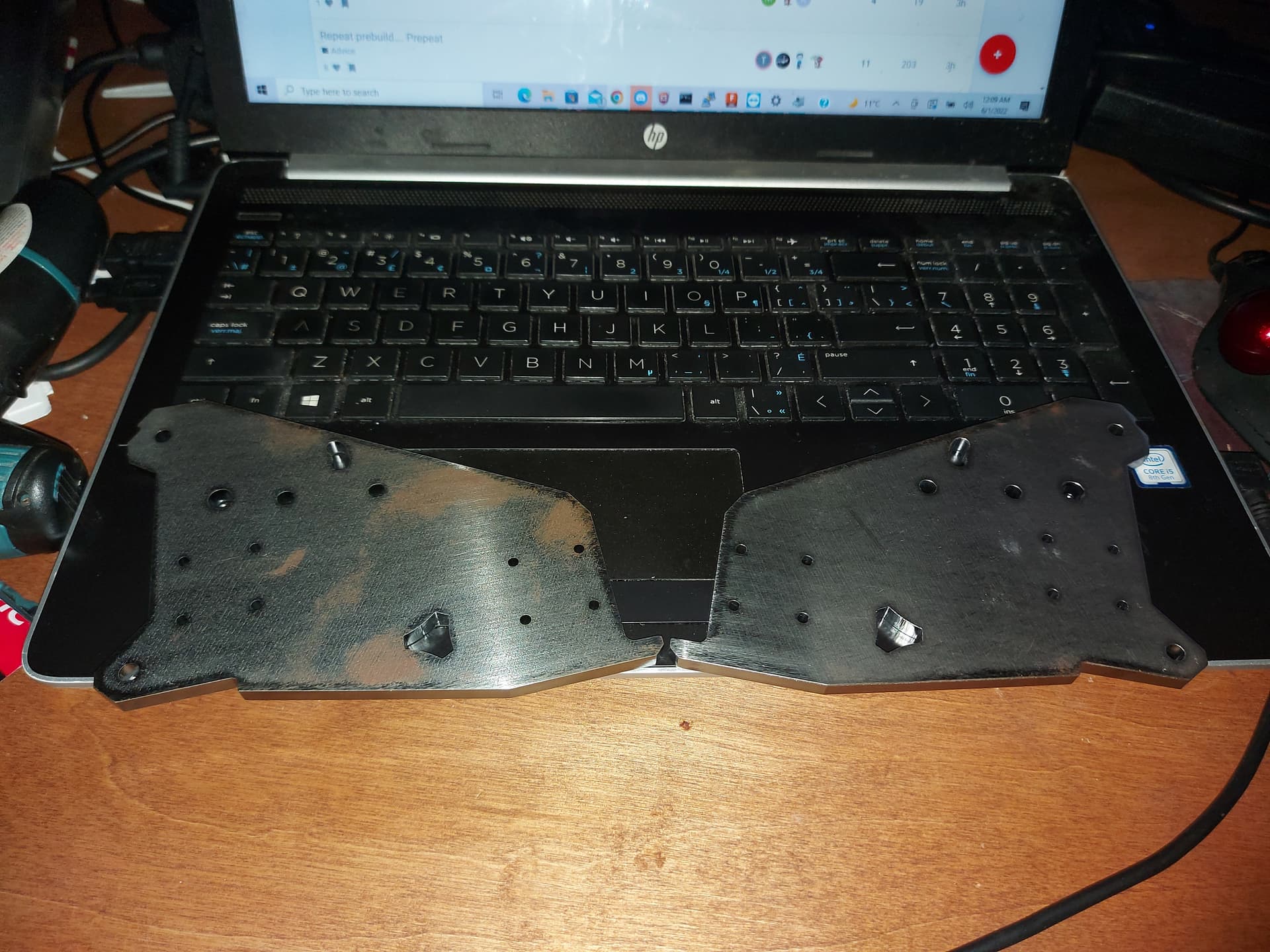
A great big Thank you! to @vicious1 for sending out some LR3 goodies! These are impressively massive, but I bet it won’t slow down my LR3 at all. I’m going to hit tbese with a bit of sandpaper, then prime and paint them faux Makita blue, since I still have some of that paint. I was seriously considering just polish and wax, too. Well, we shall see what they look like when I get then cleaned up a bit. They look OK to the eye, but I can see in the photo under flash that they need a bit of attention. There’s an advantage to Aluminum, for sure. Still, this is a working tool, and paint is a pretty sure thing for protection.
I have almost everything ready for the Repeat build finally, so a good project. 5 linear rails at 300mm, so still just a little stretched. I plan on a 235mm square bed for this one. I’m working from Ryan’s CAD for the panels, just stretched a bit for the rails and slightly wider bed.
So far, i have printed parts, belts pulleys and wheels, linear rails, BLTouch, the Hemera extruder, and SKR Pro 1.2. Still need 2 motors and a power supply.
The SKR Pro has a port of RepRap Firmware flashed on it, with an ESP8266 add on that it can use for Wifi and the DWC. If this is successful, then I intend to port over the other one. I have high hopes, since the SKR is much less expensive than a Duet 3 6HC. The Duet 3 is probably my fallback though, seeing as how I really like wifi access for monitoring and uploading sliced files.
2 Likes