Hi Everyone,
I have problem limit switch of my MPCNC, GRBL command showed me error for alarm for hard limit,
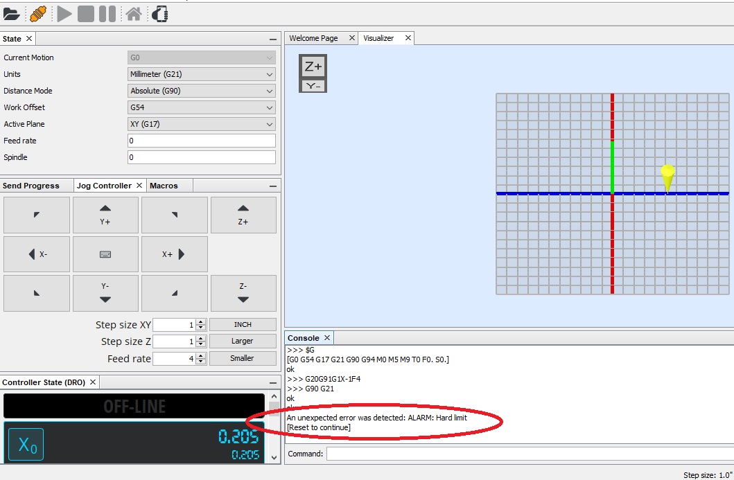
Picture of error:
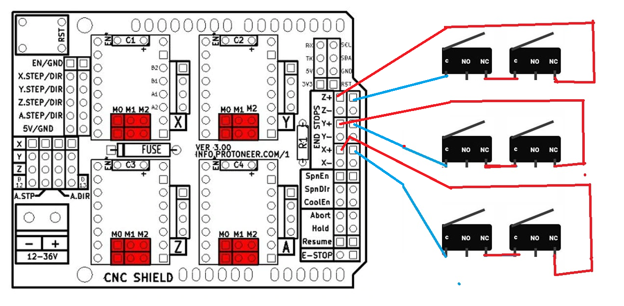
Switches wiring system picture:
Regard
Chris
Hi Everyone,
I have problem limit switch of my MPCNC, GRBL command showed me error for alarm for hard limit,
Picture of error:
Switches wiring system picture:
Regard
Chris
Since grbl 0.9 the Z limit signal pin (D11) has swapped with spin_enable (D12) so you have the Z limit limit switches wired up to the wrong pin…they should be on spin-enable (D12) and your spindle PWM (if you use PWM) should go to pin (D11)
from https://github.com/gnea/grbl/wiki
Variable Spindle Speed Output: Enables a hardware PWM output for ‘S’ G-code commands. NOTE: This feature requires a pin swap with the Z-limit D11 pin and spindle enable D12 pin to access the hardware PWM on pin D12. The Z-limit pin, now on D12, should work just as it did before.
Im using Makita M3700B Trimmer as spindler but I expect to fix Grbl command to stop movement for the X, Y or Z axis roller, otherwise damage the belt and stepper motor.
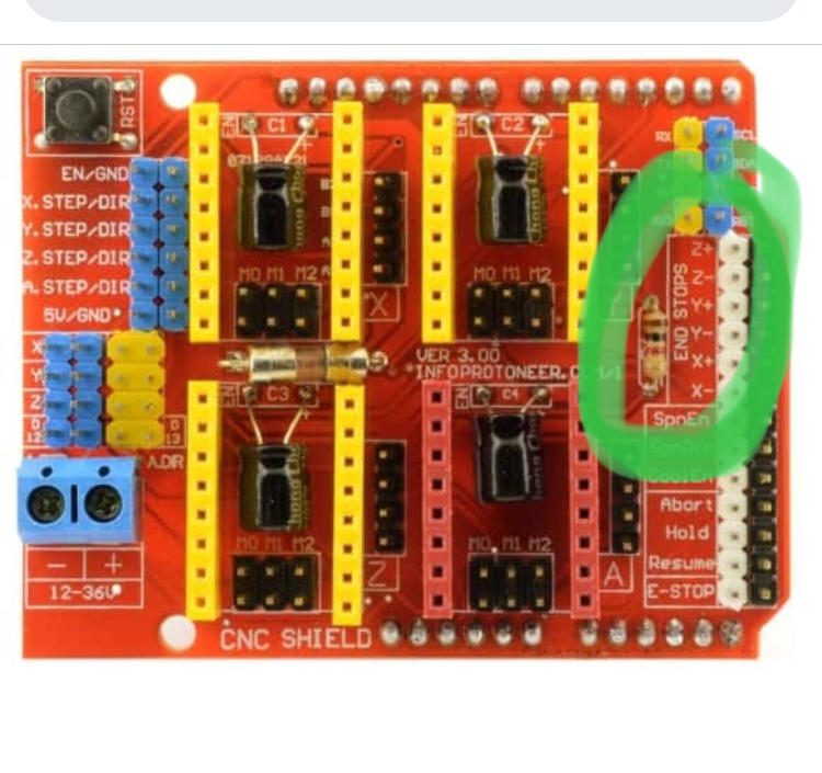
You talked about D11 & D12 pin that for Ramp or another board, but Im using CNC shields V3.0 board and it showed me x- x+ y- y+ z- z+ pins.
GRBL Command has error of alarm after hit to the limit switches that I showed the picture on this comment, and the roller refused to move when I click Y axis button on UGS software.
You see the green oval drawing mark on CNC shield picture show you where is X Y Z pins
D11 and D12 refer to the digital pins on the Arduino Uno. Uno digital pin 11 is connected to Z+ (and Z-) pins on the shield and the Uno digital pin 12 is connected to the shield SpnEn pin.
Once you have operated a limit switch GRBL goes into the ‘alarm’ state and no further movement is possible without a reset.
Can I use MPCNC without switches?
because I’m difficult to understand with limit switches for CNC Shields so you said I must connection switch to Arduino Uno that mean I must solder the switches wires to Arduino’s pin but what about CNC Shield end stop pins?
Some GRBL Forum said “build noise filter using capacitor and resistor for switches”?
I see 2 issues:
Yes. I have used grbl and Marlin, and I’ve never had endstops on my mpcnc or low rider.
I tried Z plug wire into SpnEn pin pin without connection to switches and sometime it showed me alarm.
I unplugged all xyz axis and leave pin empty and set $22=1 and $20=1 and it still has alarm problem because I think this board pin don’t have noise filter.
Or I try move to NO switches
I followed limit switches GBRL Command on this link and https://cobcnc.com/adding-limit-switches/ it dont help.
Maybe I can continue work with CNC without using switches, If difficult to solve alarm problem.
If you’re using NC switches, you need to issue a $5=1 command. By default, grbl is expecting NO switches, so will interpret an NC switch as being tripped. If you have issued the $5=1 command, disconnecting your NC switches will interpret them as being tripped, so you might want to try a $5=0 with nothing connected to see if you still get alarms.
Experiencing alarms with no switches connected and $5=0 set is a strong indicator of a noise issue, and I definitely had problems with noise using this shield. I was able to solve my noise problem by connecting a 100 nanoFarads (nF) (or 0.1 microFarads (uF)) ceramic capacitor between the signal and ground line of each of my NO switches. I just slipped the leads of the capacitors into the dupont connector so it made contact with the pins. I also had to add a capacitor to the probe connection for it to work reliably. I did not need to add the resistor that other sources mention, possibly because these pins already use the pull-up resistor of the Arduino Uno.
As @jeffeb3 states, you can certainly run without limit switches. The specified MPCNC motors running at the suggested amperage on the small drivers on the CNC shield will lose steps long before they do any lasting physical damage to the X or Y rails or belts. “Damage” to Z depends more on what tool is in place and what your spoilboard is made of, but there’s very little likelihood of permanently damaging the machine itself, except maybe bending the lead screw connector.
If the rest of your machine is operating as expected, I suggest you leave sorting out the endstops as a “someday” project and start putting the machine to use.
I set GRBL command
$5=1
$20=1
$21=1
$22=1
$23=3
They are still problem with alarm.
I wonder if I replace CNC Shield with Arduino Uno to Ramp 1.4 shield with Arduino 2560 from my old Prusa 3D printer that will be easy to setup and fix switches?
If I use Ramp 1.4 and NO switches that will be better?
I find youtube link https://youtu.be/F-tw3WuV8jk that is so awesome that I really my MPCNC do same this.
Isn’t it in alarm until you home? Does homing work?
When I pressed switches then hard limit alarm start.
When I set $22=1 for homing in command, when I press switch and alarm pop up, I try click soft reset button and I put $X, then alarm is gone and I press X,Y button to move the Trimmer for short time and alarm start again.
That is something wrong with my CNC Shield, UGS software or maybe hit by EMI.
I think about change CNC Shield to RAMP 1.4 to test.
I agree with Tom, disable hard and soft limits, disable homing and try your machine out -
$5=0
$20=0
$21=0
$22=0
If that works ok then you can re-introduce the limit features ONE AT A TIME, ensuring that the machine is behaving as you would expect.
If the machine is still giving you un-commanded alarms then, as Tom says, you have a noise problem, separate all the data lines from the power lines and fit suppression caps to the limit switch wiring as Tom suggests, If you only get the false triggering of the limit switch when the trimmer motor is running you may have an electrically noisy trimmer motor, make sure you separate the trimmer motor wires from the stepper motor and limit switch wires.
The only scenario where a MEGA2560 and a RAMPS will overcome this problem is where your Uno is damaged and susceptible to noise
This sounds like normal operation to me.
It starts in alarm. If you send $H (right?) it will home and then you’ll have control of your machine. If the endstop switches trigger anytime it wasn’t expecting, it will raise an alarm and wait for you to fix it.
The Z wire which is twist wires and I brought CAT 6 wire, I knew it has protection from EMI,
X and Y using Telephone cable but I think about replace to CAT 6 twist wire to protect.
I will let separate from Trimmer wire and Z wire that what you say.
When I set zero to $5, 20 , 21 ,22 and 23 then CNC shield is work fine.
CAT6 cable won’t protect you from electrical noise. It is designed to help prevent crosstalk which is a different problem altogether… lets see how the separated trimmer cable goes 
connect a single switch between Xmax and ground and set $5=0 and $21=1, when you switch the machine on it should enter the idle state, send a $X and then try moving the x axis from repetier host, it should move ok until the xmax limit switch is operated, when it will then enter the alarm state and then not move again until you have reset it or rebooted the Uno…this is the correct behaviour…lets see if that works ok.
Note that $22=1 makes the homing cycle available for use, but does not actually start it. The grbl command to home the machine is $H.
I tested xmax, Alarm is is active and machine isn’t move.
I’m using UGS software to control MPCNC
Make sure you match your $5 setting to your switch wiring.
$5=1 for NC switch
$5=0 for NO switch