HMM. I’m looking to just taking out the major changes in height of the bed. In that I still think that one of the ABL methods in the Marlin SW will do the trick with the precision I want not need. I’m an engineer. I don’t see why that the same procedures used on the 3D printer is comparable with a CNC . I hope to do this using the router bit closing the circuit to the switch just like the inductive Z probe. It does seem to measure points for a quarter of the board then terminates. That’s the part I cant figure out. I need to contact Marlin and find out how they set the grid pattern and why it quits. You’re right in that ABL is not easy to setup.
Unless you’re milling wet lasagna noodles your work doesn’t totally conform to the uneven bed. It averages it out. So if you use a bed probe, then you’re just transfering the unevenness to the top of your piece. Generally it’s not that big a deal, until you start v-bit cutting text, then the flatter you can get everything the better. It’s also going to slow everything down since we’re limited on Z speed. If the machine is constantly moving the z up and down with the contours of the bed, it will slow x and y to compensate.
I’ve never really looked into it, but does printer bed mesh only fix the first few layers, or does it go through the entire print? Seems like a shitty way to make good mechanical parts if it goes through the whole print.
I imagine if only worked on the first few layers, your print would not be true to scale, with a built up wedge on the bottom. Maybe i’m not fully understanding how it works, but i can see my Z steppers slightly move all the way through the print.
Yeah, as far as I can tell it will adjust the Z for the entire toolpath not just the first layers.
If you are cutting right through your material, a perfect Z shouldn’t really matter, it’ll just ding up your spoil board a bit. If you are engraving or pocketing then ABL is probably your best bet (if you can’t surface your spoil board for some reason)
I run ABL on my printer because I have a huge 12” x 12” print bed. Once it’s up to temperature it is slightly warped and is impossible to adjust mechanically.
It’s not a big deal when I print something small in the center of the bed, but if I am printing something that stretches from one corner to the other It would end up not sticking to the bed. And just 5c in temp changes the amount of warp also.
As for a router, unless we are talking about a huge work area I see ABL as a half assed way of doing it, instead of starting with a level surface to begin with and adjusting leg lengths correctly.
I’d think if you were to apply ABL to say like a full sheet LR2, instead of bi-linear, I’d probably go with unified bed leveling to define way more points than just 9. Just my 2 cents.
Hmmm. Does the software save the mesh grid someplace? If you move your workpiece to a different spot and rezero, does the software place it in the cutter part of the mesh? On a printer, zero is always in the same place, i think. That could make some trouble.
If it doesn’t save, then it seems like surfacing is more convenient, as well. Once per spoil board, unless you have a thick one and can resurface it instead of replacing it.
Its all in the setup. In a 3D printer ABL works this way. You plot the bed with a number of points. These points are saved to EEPROM, up to eight locations I believe. When the print runs, these values are added or subtracted to the zero homing value ± Z offset. It will do this for the first few layers. This is called FADE, meaning it reduces the mesh value on subsequent layers until its no longer an effect. That distance can be set Marlin. Typically 10. I’m hoping that if FADE is turned off, then that level correction continues for the whole print.
I believe you only need to plot about nine points for the whole work surface to remove any bed to router X/Y travel error. At least that’s what I’m hoping for.
Don’t they usually read the work pieces and apply it to the top surface? PCB are cut this way to eliminate surface imperfections. 2D cuts on curve ect. Can this be applied this way or does it have to be to the bed?
In answer to Barrys milling comment, I agree. However what I need is to be able to engrave shallow (<2mm) letters and lines into a large surface. I’m not worried about the Z axes moving out of tram with the bed. In my application that’s a very small error in the scheme of things.
Maybe I’ll figure how to adjust the four MPCNC legs so the XY travel is parallel to the bed. Then use ABL if I need to compensate for a slight bed warp.
I’m not sure. I don’t think it would make difference. My understanding (could be wrong) is that the mesh value is interpolated and then added to the proposed cut Z value. The values in the mesh are + or -.
Agreed, there are many other ways and opinions to deal with ‘level bed’. But I guess my problem is WHY can’t I get Marlin 2.0.5.3 to scan the entire bed??? Weather it makes sense to use it or not isn’t my real concern. Guess I’ll pass this SW (or my) problem over to the troops at Marlin and find out. Thanks for all the help however. Doug
I think if the middle of your work area was 2mm lower than the edges, a 1000mm sheet good would conform and be touching the spoil board in the middle. It won’t instantly react to a pebble under the work, but it will generally follow the spoil board.
But the errors you can compensate for with bed leveling include:
slope of the XY plane, because the feet aren’t the same length
sag in the gantry, because the tubes are bending over a large area (this is also true for LR builds)
twist, slope, or bulges from a not-perfectly flat or swelling table surface.
If you surface your spoil board, you could actually be making the spoil board more like “rolling hills” because it will follow whatever inaccuracies you have in the XY plane that the router follows. And it is totally fine, because you are talking about tiny Z over huge XY, and our materials will conform (maybe carbon fiber wouldn’t but wood is heavy, and doesn’t have that kind of strength).
The bed leveling compensation in Marlin can be set to either average out the compensation by a certain Z value, or to just keep it the whole time. Even on a printer, it really is better to keep an eye on the numbers and make sure it isn’t compensating for some huge error. In a printer, the goal is a perfect first layer, the total dimensions of the part aren’t going to be exact (to within a tenth of a layer height), so the compensation isn’t really noticeable in the final part. I get much more error in dimensions from warp, which bed levelling significantly reduces by having a consistent thickness on the first layer.
I haven’t ever used ABL though, I use bilinear on my printers, and I didn’t know you could send a command to probe in a certain region. I will definitely have to try that.
I got it all figured out and working. I think we have been over thinking the problem and and I wasn’t adhering to KISS. Got to go now but I’ll post what I found and where it lead me in a bit. thanks all cheers.
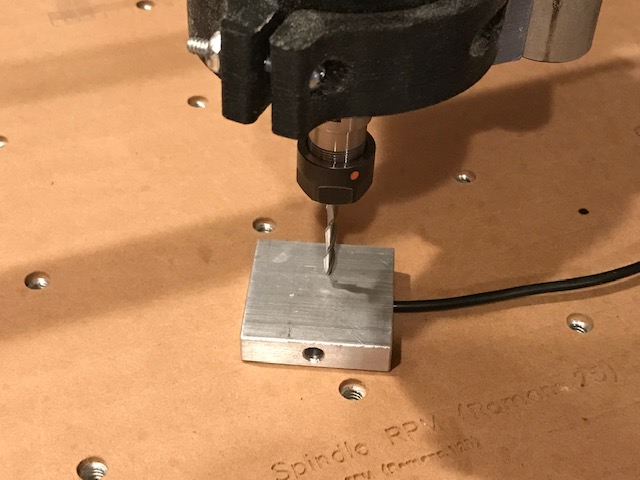
Here in a nut shell is what I did. There are two things that need to be adjusted the best you can. one is the Bed must be parallel to the XY plane of the router. The other is that the Z axis is perpendicular the the Z axes plane. I fell back on the simple mode of Corner Probing. In 2.0.5.3 you can set it to probe the center too. That gives you two indicators of parallel error. I’ve tested it and measures quite accurately. I started by using my standard XYZ home using a touch plate and nail in the spindle. it step through the corners and center points manually. the first point (lower Left) is the reference point and saved in memory as 0.0. Pressing the control panel button moves the router to the (lower right) point and drops to Z0. Using the same touch probe, adjust the Z axes up or down until it just touches the button. Press the button again for it to move to remainder of the five points. There is a menu item that will display the the point values on the LCD or G29 T on a serial monitor like Pronterface etc. Now adjust the corner legs for that amount and repeat and repeat. It’s a very good way to measure non-parallelism. I made four small screw jacks to adjust the legs. If you turn auto-leveling on it will compensate all across the bed.
I hope this helps someone. The changes to configuration.h that hard. Let me know if someone needs help there. With auto-leveling on it will make up for minor board warping.
I’ve tested this only on MARLIN 2.0.5.3 so far, but it is worth the upgrade. I hope this ramblings are clear