Having trouble with SKR Pro V1.2 set up for CNC

Hello!

I have been making things in Tinkercad and Easel for a while now (I work in a school where we have an X-carve and Makerbots) and I wanted to be able to carve at home, so my friend and I stumbled upon the MPCNC Primo kit and thought we would give it a try. Everything has been super easy, the printing of the parts, assembling the machine, flashing the board, etc., but now I cannot seem to land on a relatively simple way to create and carve my designs.

I purchased the SKR Pro v1.2 board along with the LCD screen and have no trouble loading up Gcode from a SD card, but what happens next seems to vary from day to day.

Here are the machine specs:
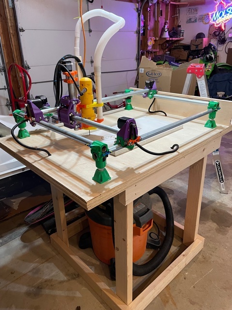
-Primo build kit
-SKR Pro v1.2
-Bigtree tft 35 V3.0 LCD screen
-Marlin 2.0

Just to catch you up here is what I have tried so far:
-load .dxf file into Estlcam
-create a tool path in Estlcam
-save file as a CNC program
-copy file to SD card
-select “print from media” on LCD screen
-select the gcode file and hit “print”
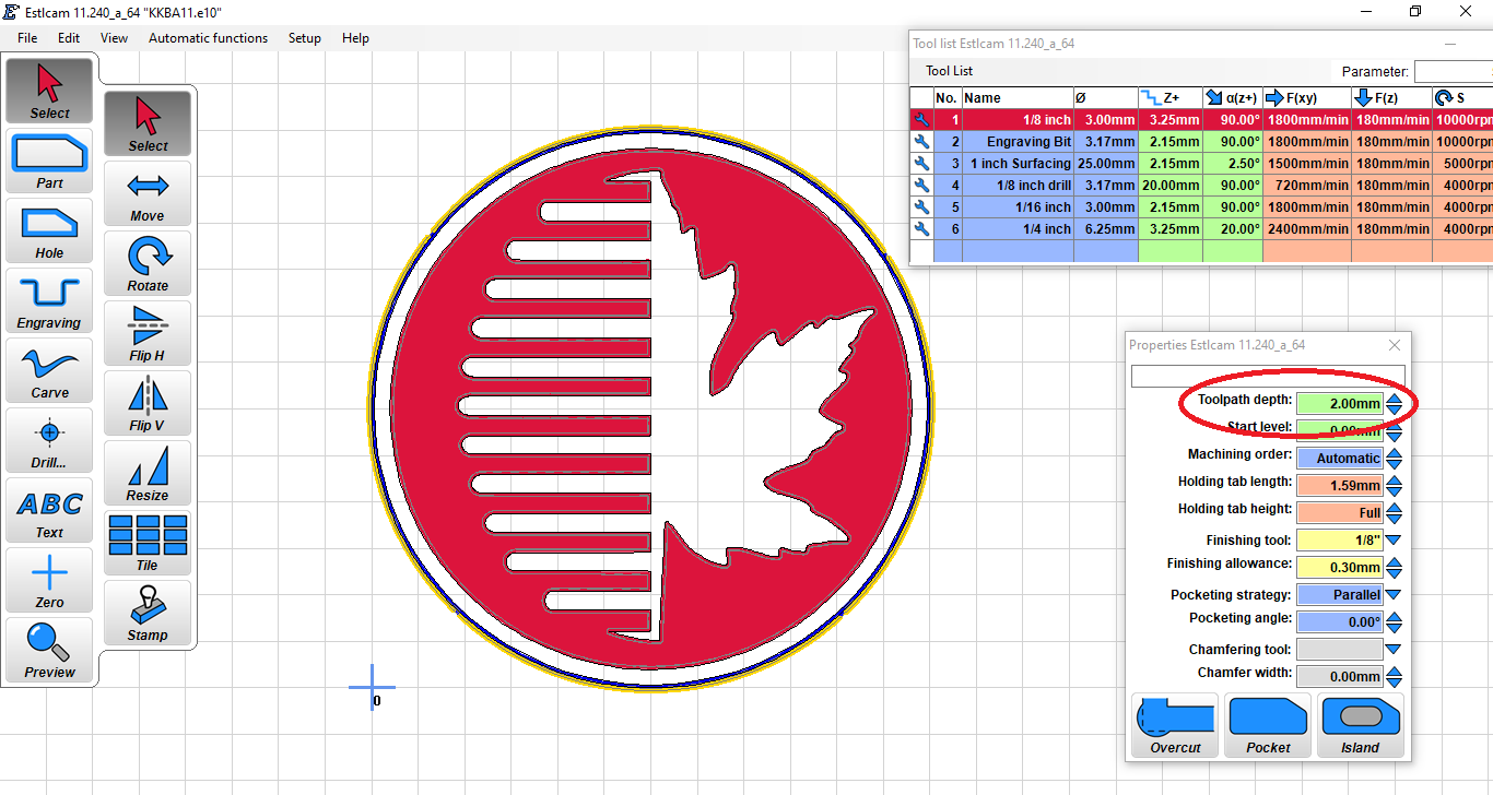
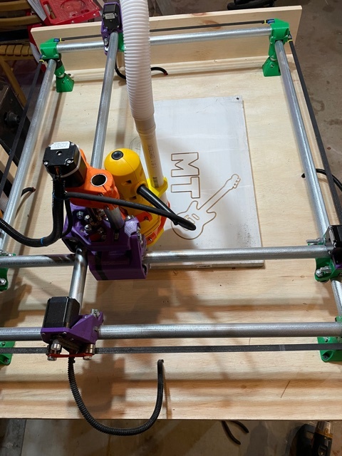
-at first it created the shape! (I had taped a marker to the router) but then I noticed when I went to actually cut, the cut depth settings were very off
-go back into Estlcam and play around, but can’t figure out how to change the cutting depth, or any other cut settings for that matter
-tried to use Repetier, but that software seemed so complicated and very geared towards a 3D printer
-tried to use Onshape, but I am so confused of what that software even is (haha)
-tried a number of programs to make my own .dxf file, but they all seemed so complex
-tried exporting a design from Easel and manually editing the gcode using a tutorial online, but the machine just moved around randomly and “finished” printing in a few seconds

I know Estlcam isn’t compatible with my SKR board, but the one time the machine seemed to work (a little bit) was when I created a tool path on a .dxf file and saved the CNC program onto the SD card as a .gcode from there.

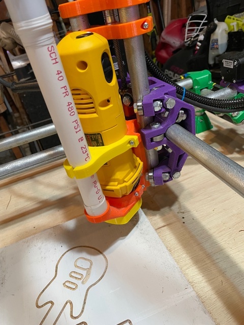
So basically I am very stumped at this point. I know this machine has approximately ONE HUNDRED MILLION OPTIONS, but all I want to do is use it as a CNC router for wood and maybe plastic. I am aware there will be a learning curve on any new software, but I am just lost in the purgatory of which one(s) I should be using and investing my time trying to learn, so I keep jumping around. Like I said, Estlcam was the closest I have gotten to success, but now when I make a tool path it won’t even plunge the tool into the wood. Once I hit “print” on the LCD it lifts the tool up and starts slowly moving on (what I think is the correct) the tool path, but I can’t get it to stay anywhere near the wood it should be cutting.

I hate posting on forums, but after 3 months of trial and error I am giving up on figuring it out myself and asking for help. I know there has to be a way to make this work. Thank you in advance for any advice, and apologies for being a fool. I am usually pretty good at figuring things out, but I am beyond lost when it comes to the myriad of options available for this machine!

I’ll start with this: I’m using Estlcam to generate gcode files. I use a Duet Wifi on my MPCNC Primo, and will be using the SKR Pro on a LowRider. I will NOT be using Estlcam’s control program, but uploading files to the controller (Or using the SD card.)

Did you set the Z=0 origin of the machine? Do you have a touchplate or other means of setting the machine depth?

The depth should at least be consistent with what you set in Estlcam. That is, if you tell it one pass at 1mm, and a second pass at 2mm depth, the second pass should be 1mm deeper than the first, even if the first isn’t right. If this is wrong, then you’ve got something set incorrectly in your firmware. If you are using the 8mm leadscrews (2mm pitch, 4 start) for the Z axis, it should be set to 400 steps/mm. Hopefully you are using the pre-configured firmware in the Marlinbuilder releases.

Then, it is a matter of setting your Z=0. You can jog the machine to the top of your workpiece, and then issue a G92 Z0 command to set the firmware position to zero, or if you’re using a touchplate, you set it to the touchplate’s thickness. (The touchplate in the V1 shop is nominally 0.5mm thick, so G92 Z0.5 would be the command.)

You can adjust the steps/mm from the LCD screen, just make sure to save the settings to the EEPROM.


Here you can see the setting. This should be one of the things that comes up when you select a line in your drawing for a tool path. “Start Level” is also taken into account as the base depth. If you set a “start level” of 2mm and a cutting depth of 2mm, it will assume the first 2mm is already cut, and go to a total of 4mm from your workspace zero depth.

Recommended reading on Estlcam

Welcome to CAD…

You can actually get reasonable results in TinkerCAD, if you export a file as a .SVG, (Scalable Vector Graphic) you can import that file into Estlcam and work with it. TinkerCAD will export the profile that intersects with the origin plane. This is probably your fastest way to work if you’re already familiar with TinkerCAD.

Most CAD programs allow some very sophisticated drawing, so they are necessarily complex. It’s a big learning curve, but I think you’ll eventually want to go there. For now, I’d probably focus on understanding the Gcode generation and machine use, you can build your design skills up after that.

I can empathize, but this is a pretty good community, and we’ll all try to get you up and running on this if we can.

Seriously, if this group of people can’t help you figure this out, nobody can. And you won’t come across a nicer, more patient pack of rabid dingoes bunch of hardware and software folks anywhere. And if all else fails, head over to the Random section, and look up recipes for smoked meats… A good brisket or tri-tip is sure to brighten your day! (hoping desperately that you aren’t vegan)

1 Like

Did you let the Estlcam controller program connect to it? if so try to flash the board.

@MoveAround44 welcome to the club! Like @kvcummins & Dan said, there will always be someone that is willing to help you out.

Did you confirm that the V1 test crown drew correctly before you tried your own CAM? Also check out the Estlcam basics page like @SupraGuy suggeted.

Thank you! I tried the test crown again and it cut well, I just had to make sure I set the home position of the Z so it was within a millimeter or two of the wood before hitting “print”. I will keep playing around with some of the CAD software and give the TinkerCAD export a try. Hopefully I can work backwards from the test crown and figure out how to make my Estlcam files cut again.

2 Likes

Success! I was able to focus on using Estlcam and I finally found a way to generate readable files using Illustrator. I still need to make some tweaks, but here is a simple summary of how I am successfully using my MP CNC.

I will create or edit simple images in Adobe Illustrator, then save them as an .svg file. It was a quick google search to figure out how to upload a jpeg into Illustrator and turn it into an editable image. The other option is to download pre-made .dxf files, but those will load right into Estlcam, so I don’t even need to open those in Illustrator.

Next, I open up Estlcam and open the .svg file. From here I can select individual lines and set the cut depths for each part. My test projects have all been engravings on pine, so my tool settings are 6mm/s feed rate, 3mm/s plunge rate, .5mm a pass, 1.5mm depth of cut for a 1/8" bit.

Once I have all the parts I want to cut selected and my tool settings where I want them I click “File”, “Save CNC Program”. Then, I simply drag and drop the .gcode file onto a 4GB SD card.

My machine runs on the SKR Pro V1.2 board with the TFT 35 V3 and Marlin 2.0 (downloaded June 2021). I have been using an SD card plugged into the LCD screen port to upload gcode. When I first fired it up I had to push down and hold on the dial control until it gives me the menu to enter Marlin Mode.

Once in Marlin, I scroll down the menu and select “motion”. Using “move axis”, then selecting each axis and moving the machine with the dial, I move the gantry to the back right corner. Next, I go back to the menu, and under “motion” select “home x”. When I select this it lifts up the Z axis about a 2-3 cm or so, then moves the x over about 4 cm. After homing X/Z I go back to the menu and select “home y”. Once Y homes, I go back to the menu and select “motion” “move z axis”. I then move the bit down until it just barely touches, or hovers above the wood.

Finally, I go back to the main menu and scroll all the way to the bottom to “print from media”. I select the file I want to print from the menu and then select “print”. I turn on the cutting tool and off it goes!

And that is my method! I am intending to use this machine to make guitar bodies, pick guards, wooden toys, signs, and other little things for around the house. So far on my test runs it seems to run really well. It did take me a while to figure out the software side, but I like what I have been able to do with Illustrator and Estlcam. Thanks for the help!!

3 Likes


3 Likes

Nice build! Glad you’re up and running. Look forward to seeing your guitar bodies.

BTW, are you using the housings from an old Zip drive for your controller? Nice recycling. :grin:

Yes! It just fit into that old zip drive housing too easily, I couldn’t not use it.

2 Likes

Oh man. Now you got me thinking. Some TFTs have a USB port for thumb drives. I wonder how it would see a Zip drive or USB floppy drive…I know I got one in a bin somewhere…