I tried to connect the 12v Fan 0 port from my SKR Pro 1.1 to the PWM/TTL connection on the laser driver board before I knew better and it made no difference to the laser output which was full power from the moment it was plugged in. They are not kidding about these things being dangerous!
No amount of fan speed control changed anything on the laser even though I could meter the connection and the voltage was going up and down.
More forum searching led to this post:
where @dkj4linux talks about the dangers of connecting 12v to a port expecting 5v
I don’t like answering these questions about lasers because there is so much that is unknown. But here is my guess:
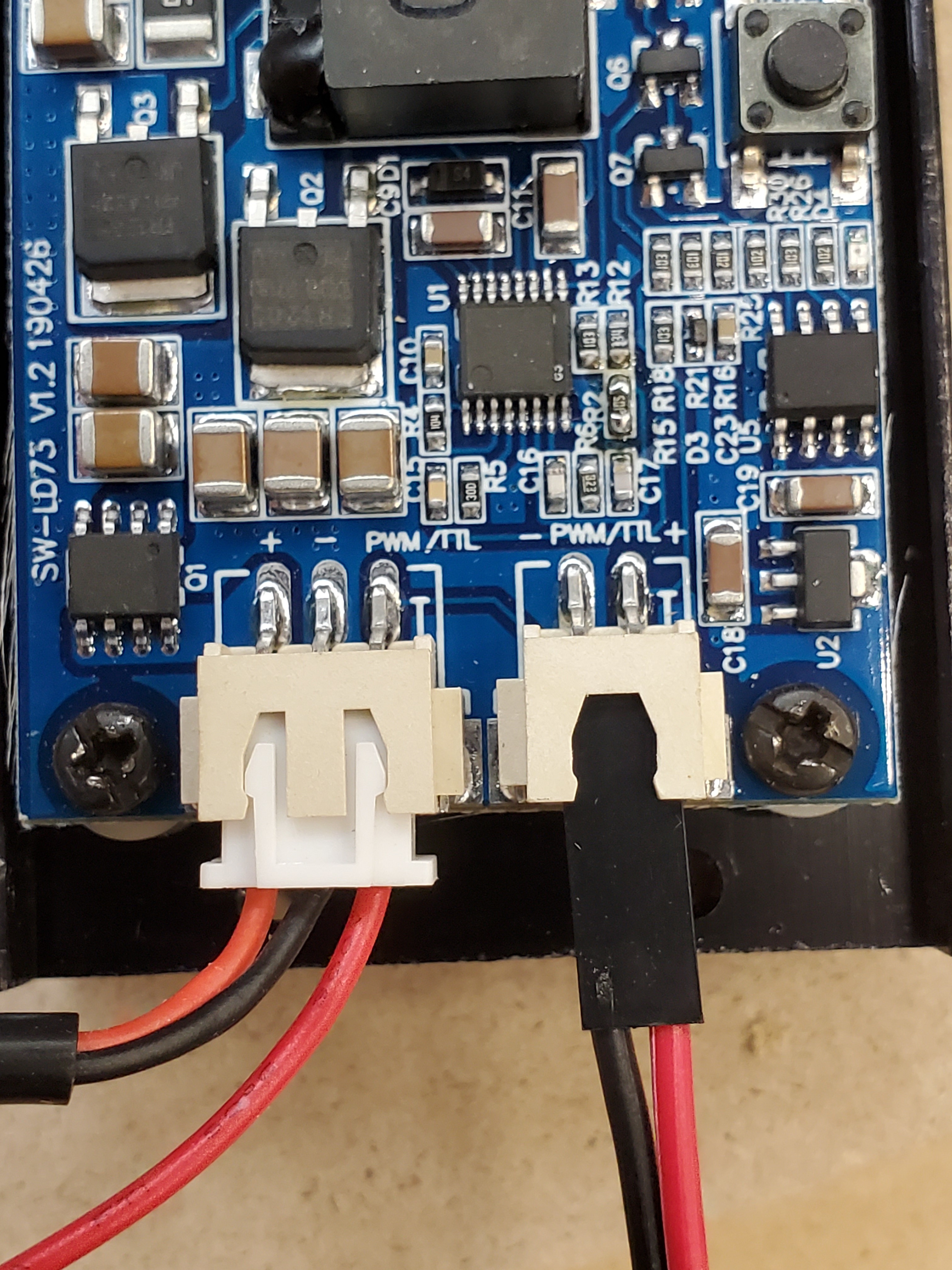
The left connector on the laser says +, -, PWM. I think you should connect it this way:
+: 12V at the power supply, or right at the input to the skr
-: Ground at the power supply, or right at the input to the skr
PWM: The negative side of the fan0 terminal.
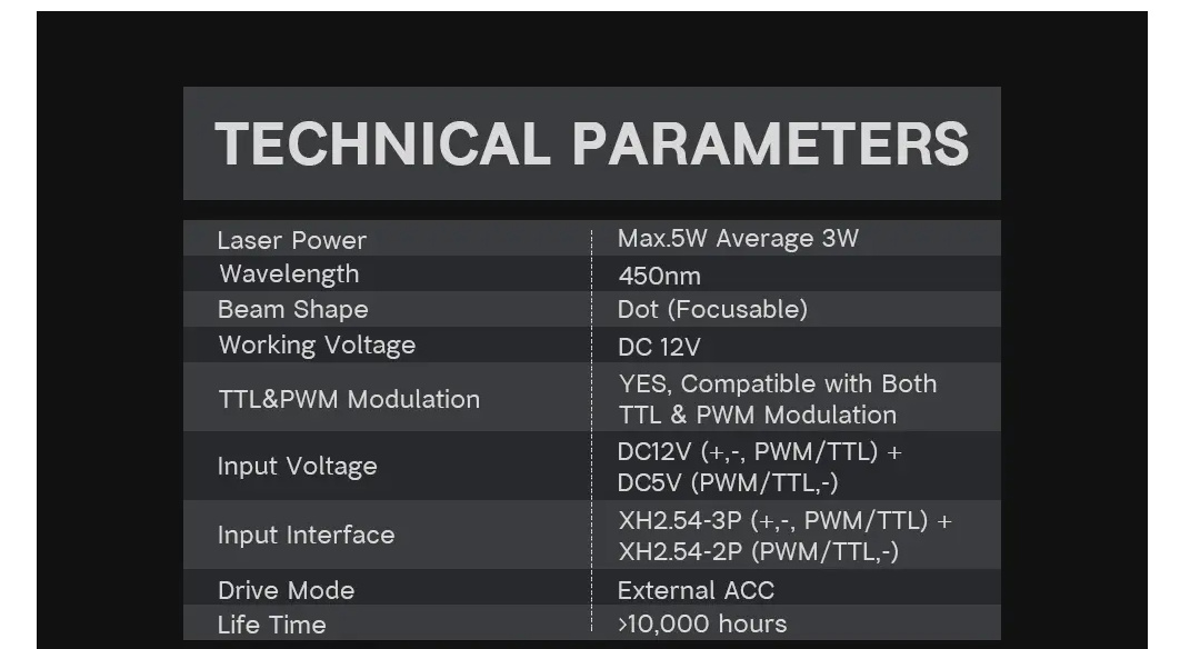
Here’s why. The data sheet isn’t very helpful, but it certainly looks like it accepts 12V PWM. It also clearly accepts 5V, so maybe the same input can handle both (very possible) or the left side is different from the right side. The logical thing to think is that the fan port on the skr is a ground and a 12V output that toggles on and off. But most transistor devices can sink more current to ground than pull to high. So it is very common to eke out a little more capacity by putting the switching on the negative side (low side drive). So in fact, the negative terminal switches between 12V and ground when the fan is on. So if you connected to the positive side, it would act like it was always on completely.
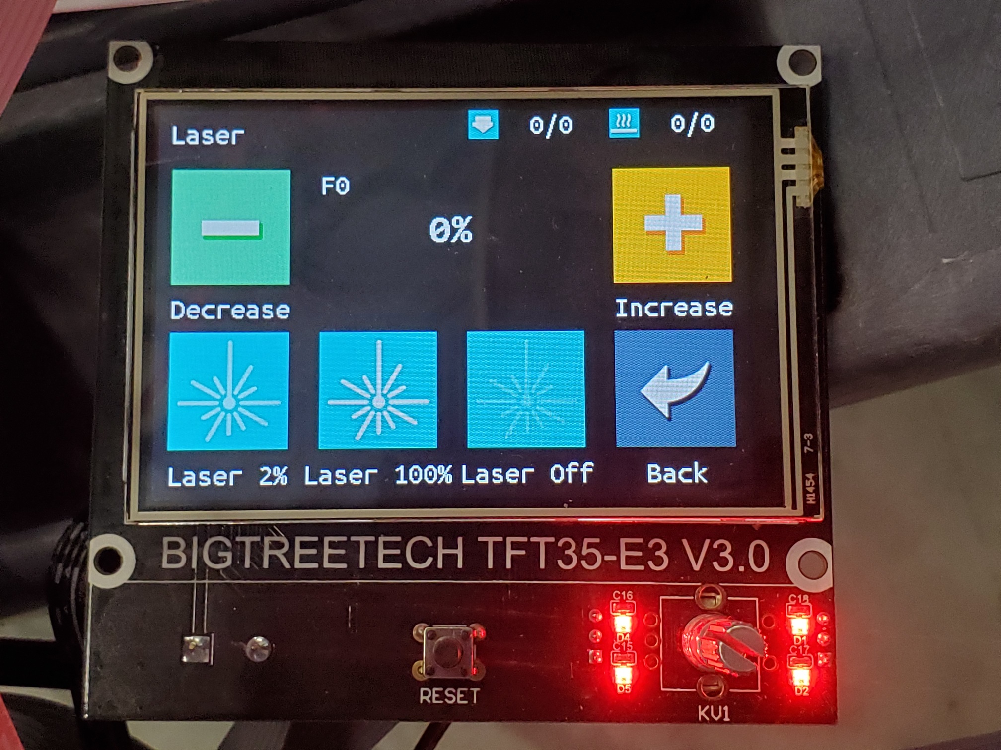
The problem with that is that it is inverted. So M106 S0 turns it off. M106 S255 turns it off.
Those buttons on the tft are not special, they send M106 and M107 commands. IIRC, the knob also adjusts the value there. If you can get it to work that way, but backward, you have a sort of working solution.
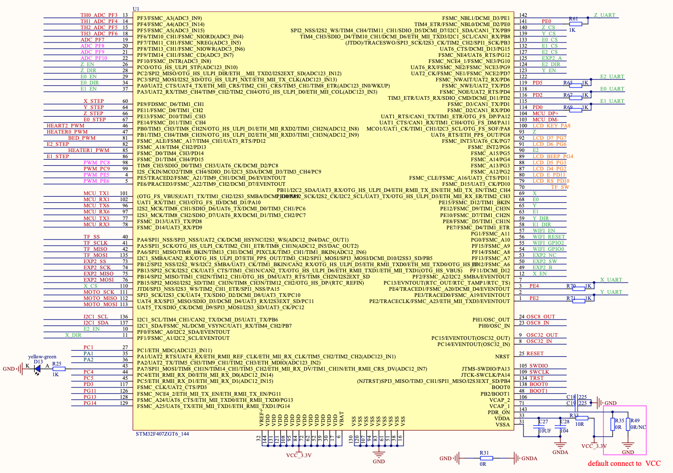
If you are interested in it not being reversed and toggled by 5V, then change the fan pin in the pins file to another pin. You will need a pin that is capable of pwm (sometimes called analog) output. I can’t tell from the schematic, but I suspect most pins are on that chip. You might try one or two first before worrying about it. The pins file will define what the endstops are and what the fan pin is, so it is easy to just swap them.
I am guessing the pins with something like TIMX_CHY are going to be pwm capable.
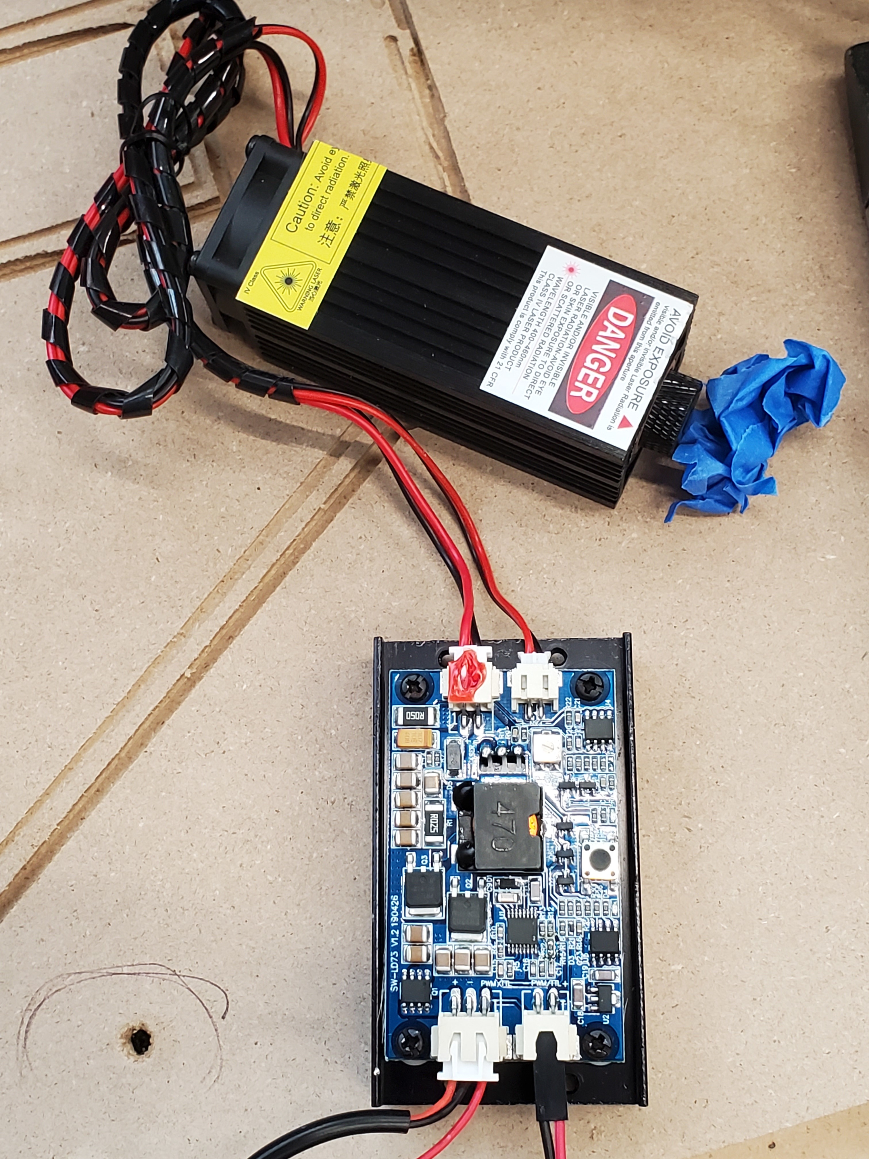
I’ve been meaning to write up a how-to, but it looks like you have my same setup, same laser, same board.
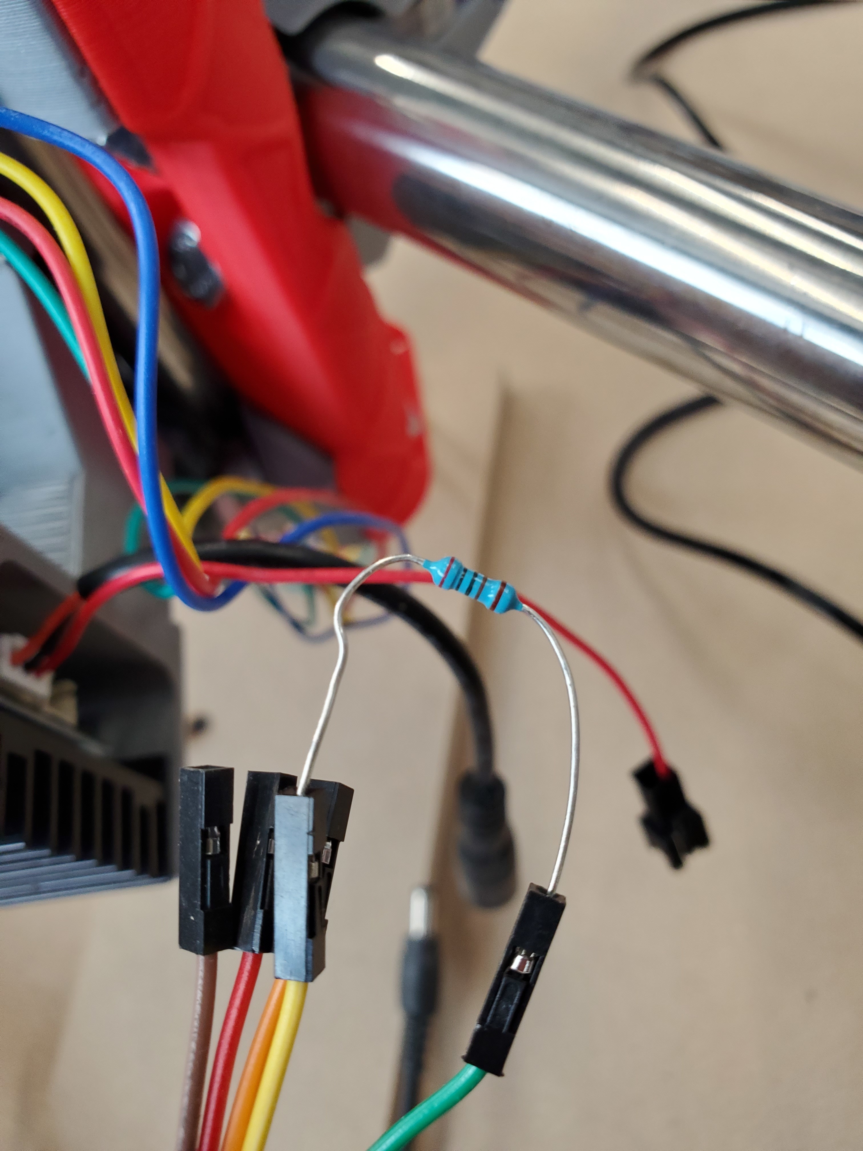
You need a pulldown resistor, I think mine was 2.2K. Ballpark in that area is fine. I presume you’ll notice (be careful!) when the laser isn’t even connected to the SKR the laser will be on full blast. They didn’t want to spend the $0.02 on a resistor. I.e. you need to 2.2K resistor, or thereabouts, between the logic input and ground at all times, plugged into the board or not.
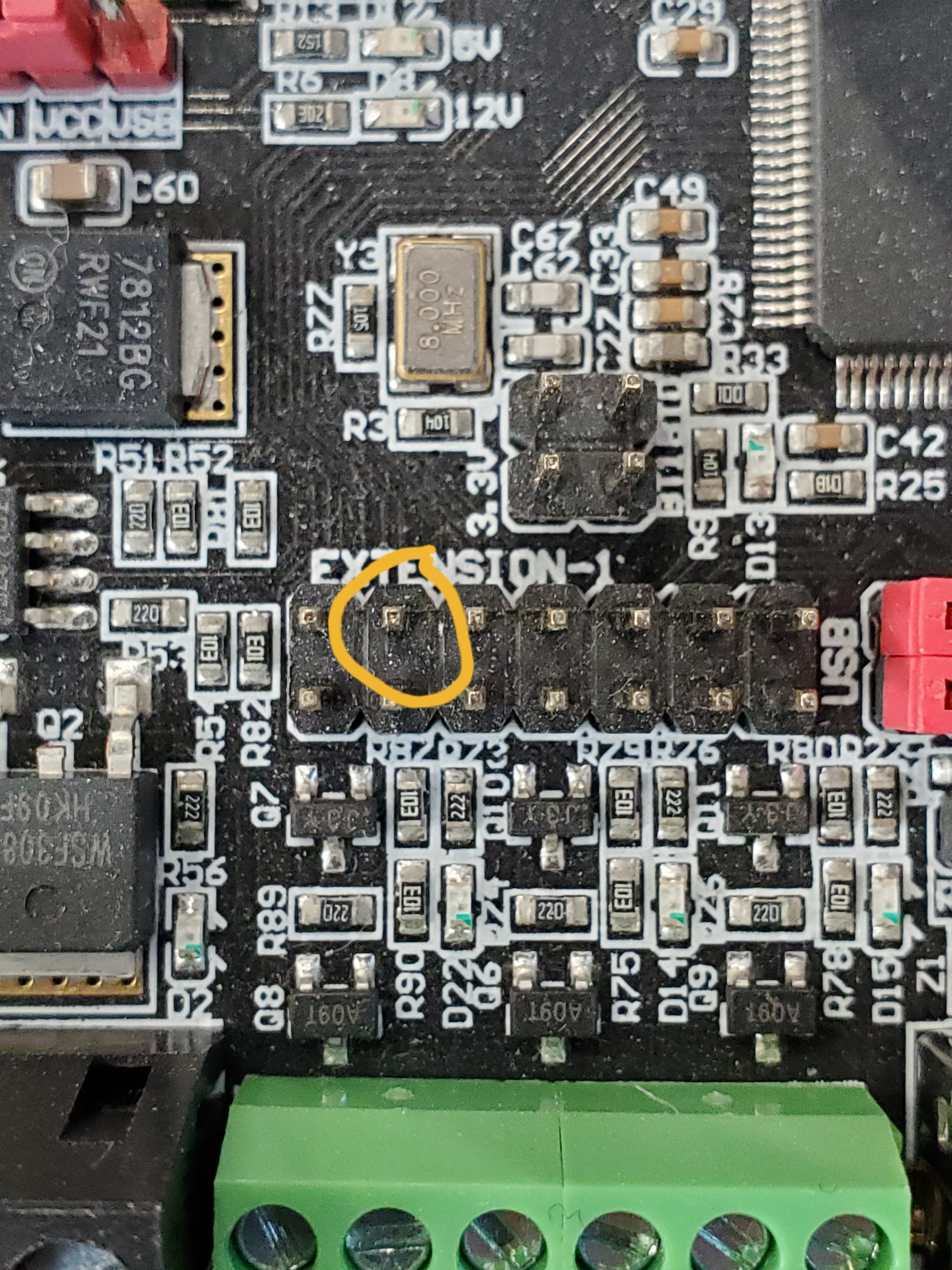
I’m not using the fan pin, I’m using PC9 (on EXTENSION-1, PWM capable once you trick Marlin). I was afraid the fan pin voltages might toast something. When “off” the logic pins don’t bring down the laser input “hard enough”. You need that pulldown resistor to help bring that pin down to ground, 0V. Perhaps via Marlin you can put that pin in “pulldown mode” if it isn’t already and that might help, but then I worry about bootup time lag for that to kick in, it’s just safer to have a physical resistor there.
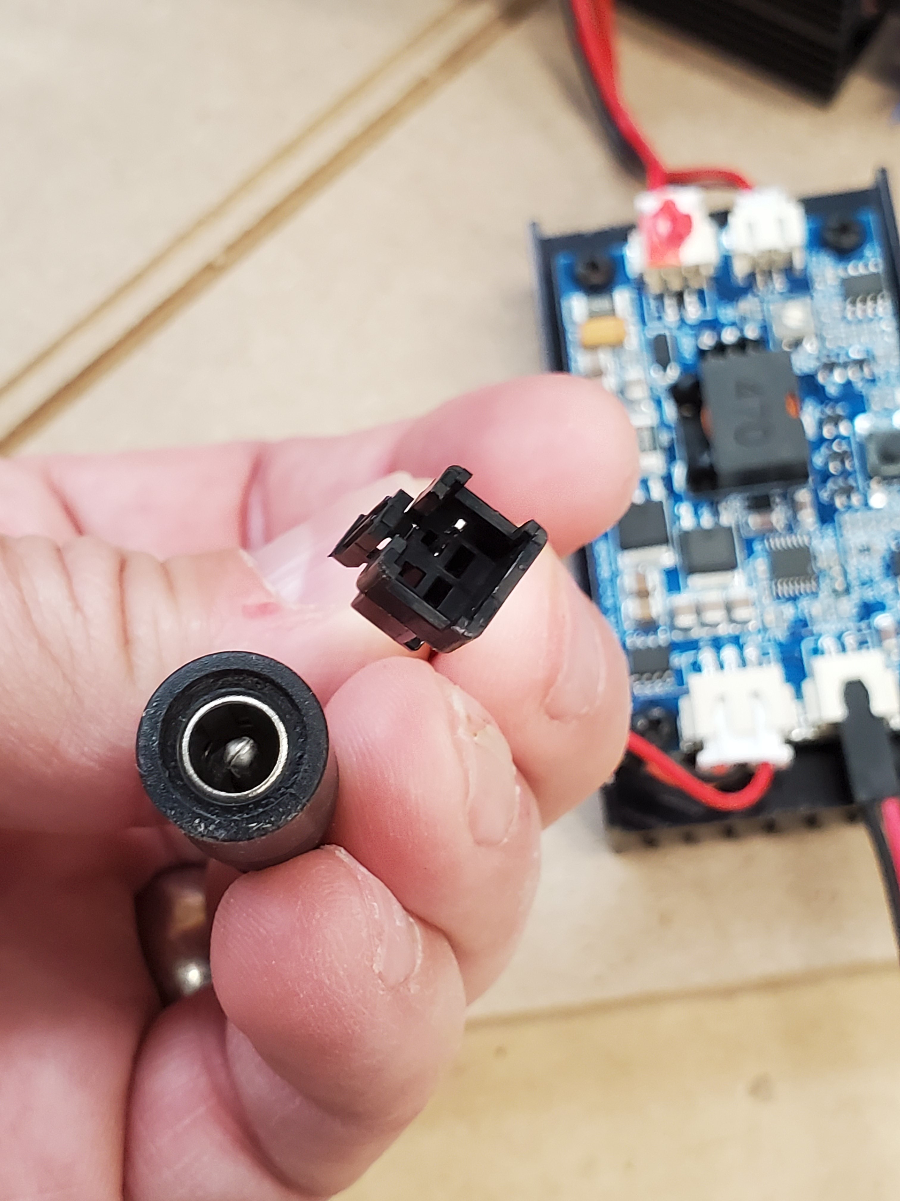
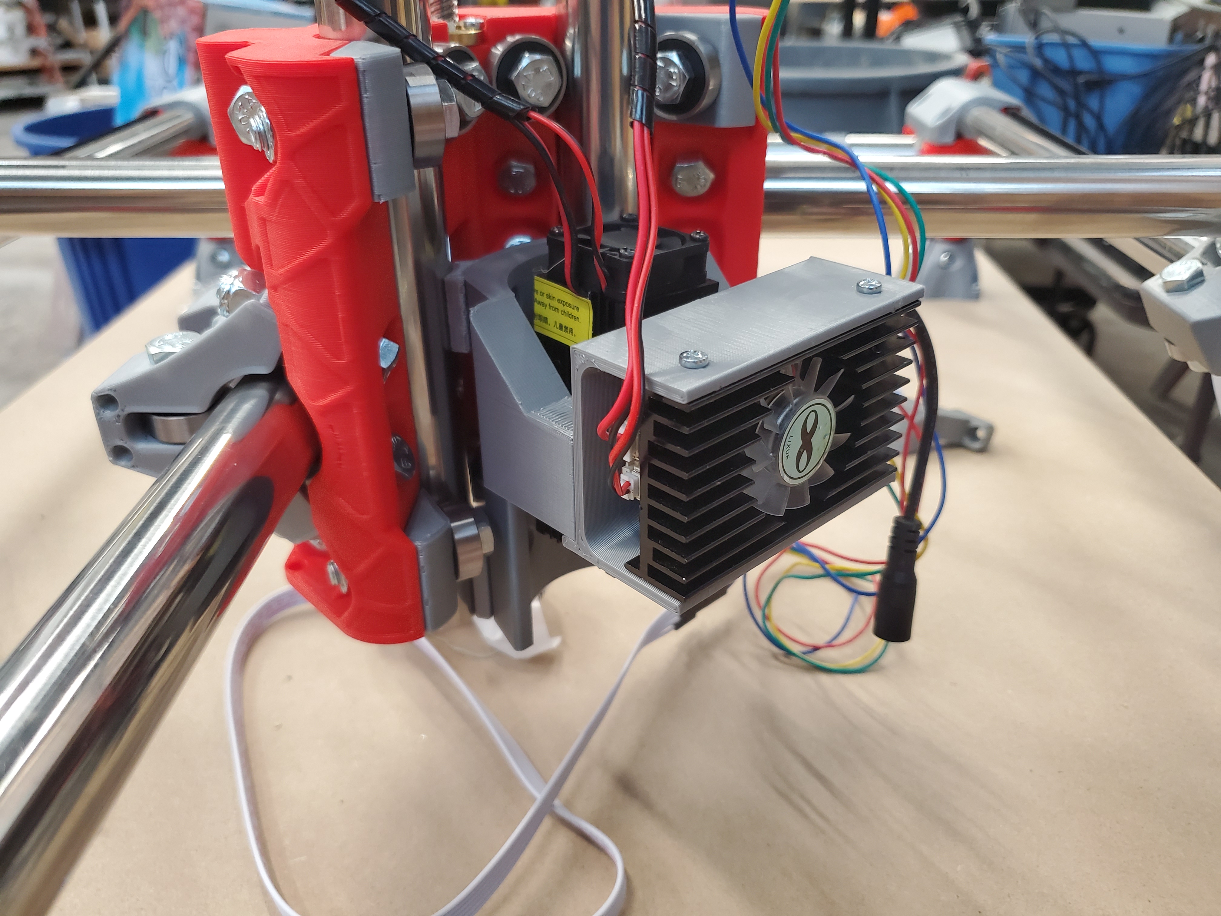
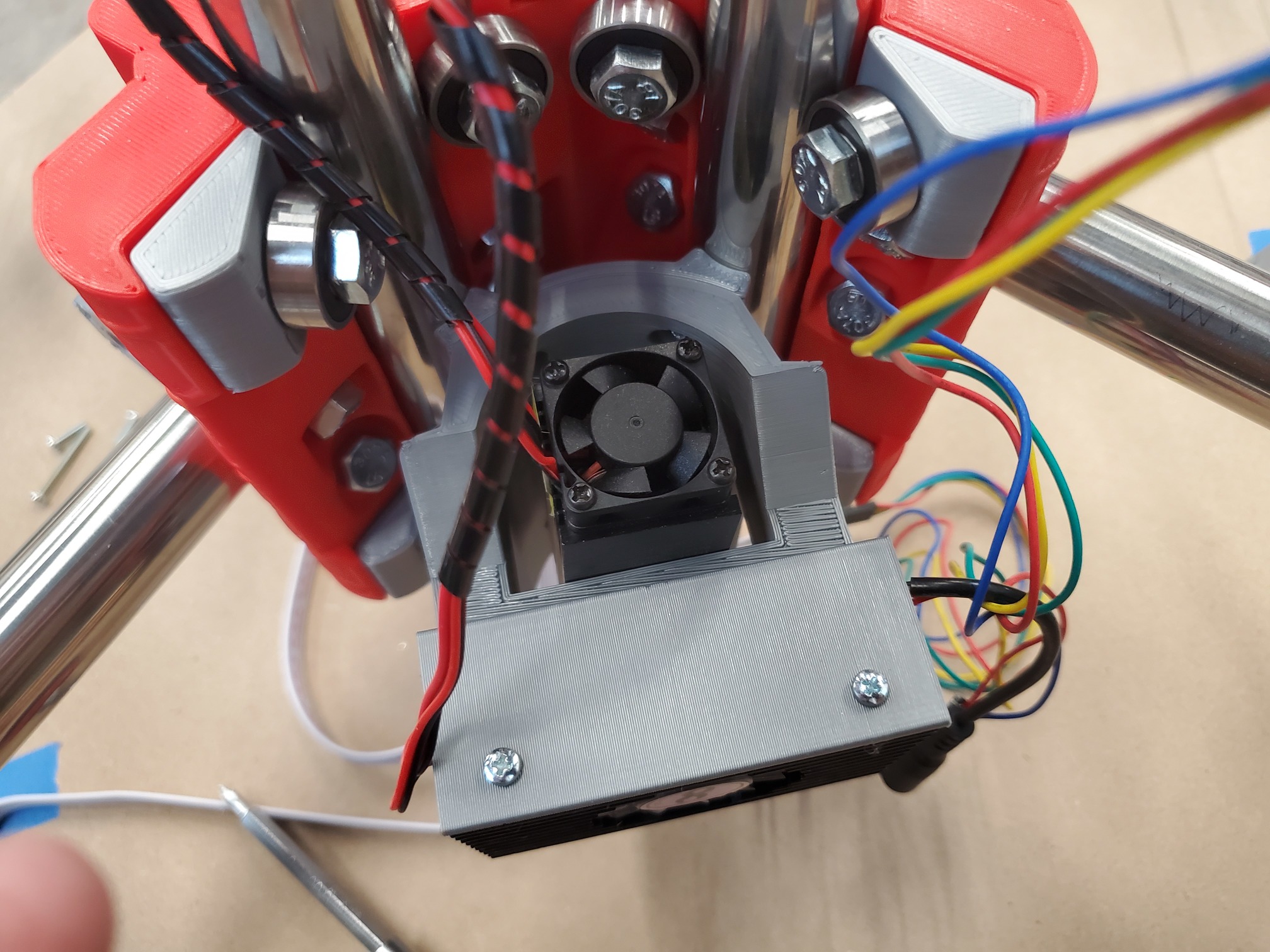
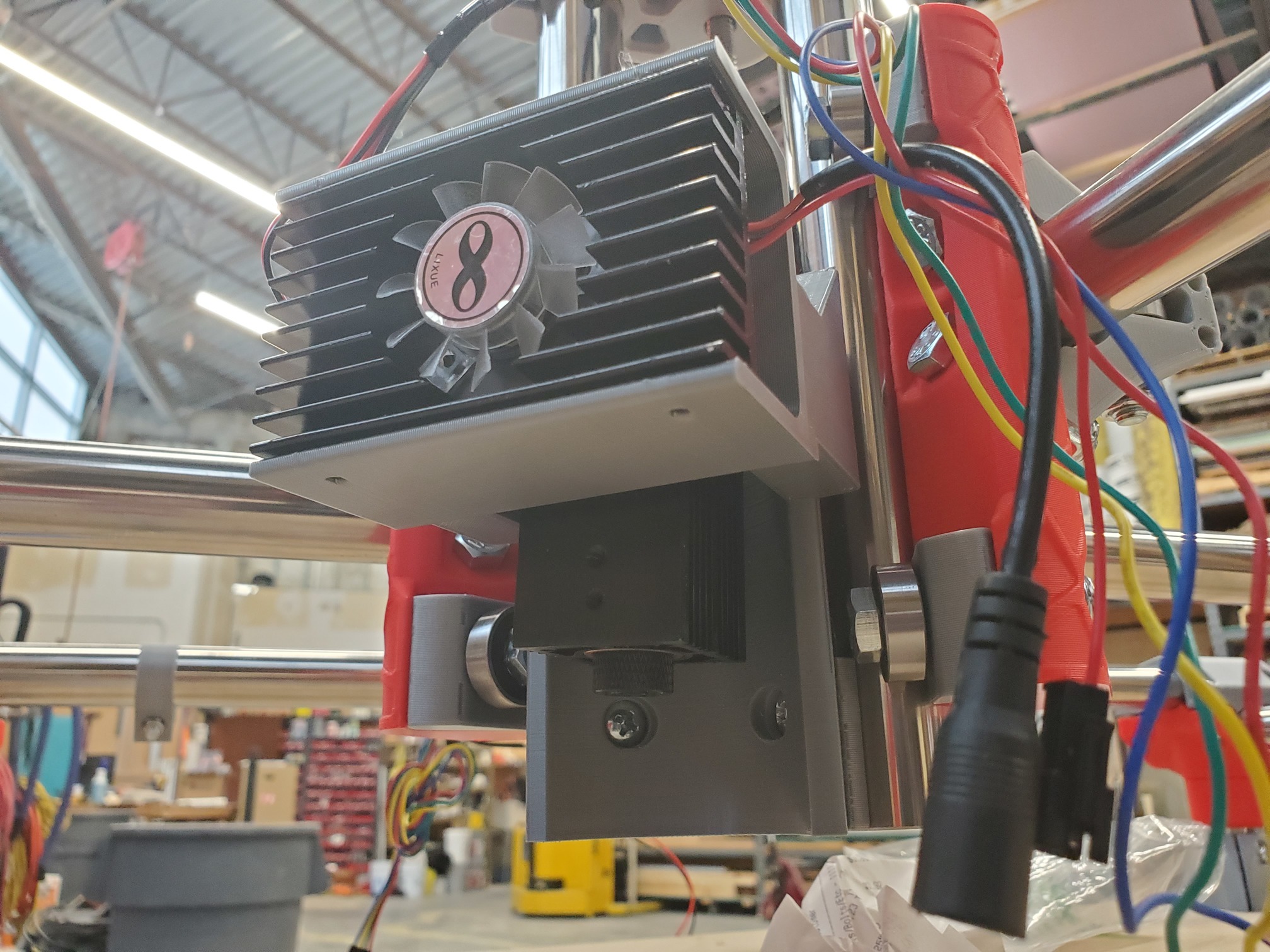
I will try to look at that tomorrow. What did you use for a tool mount? Could you send some pictures of how you mounted the driver board and the laser?
So my EE level is super basic. I have a 2K resistor. Could you very specifically tell me where I need to connect it? Should I connect it between the negative and TTL pins on the three pin connection that also has power?
I used a dupont connector to make that little resistor dongle hanging out the side there. So far as I can tell those pins are the same as the pins in the connector above it. So I hook the yellow wire to PC9 and then red/black to the 12V input power screws.
That red burly mount is here on my website (can’t be bothered to create a thingiverse ID). You’ll need to rotate it before printing.
This part I need more handholding one. How does Marlin need tricked and what specifically in the firmware am I changing? I looked around and found several sections with pin and pinmap but again no clue how to type the magic characters that brings meaning to my life… I mean my laser’s life.
Yeah, using the 12V power supply (v1 supplied) that came with my Rambo (now used for the SKR instead), powers both the SKR and laser. It’ll take me a while to dig up the Marlin steps. Yes, that’s PC9.
Many thanks for the suggestion of the 2K2 resistor across the two-pin input, my laser is now not hard on.
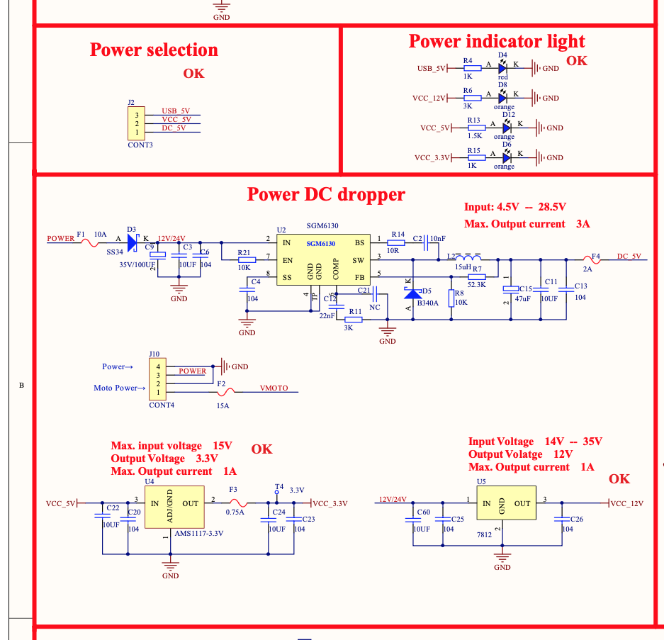
And thanks for the screen shot of the Technical Parameters (I didn’t get this with my unit)
My question now is; I have been trying to connect to the GT2560 board on a Geeetech i3 printer using the PWM fan output. Being cautious, and not having any technical info for the laser, I follows other advice and put a 8705 voltage regulator between the fan PWM out put and the 3-pin PWM input ( the 2-pin has the 2k2 resistor).
If it read the Technical Parameters correctly, I can feed the fan input (12v PWM) directly to the 3-pin PWM input? I don’t need the 8705 and although the laser is now working with it, I should get improved laser output?
Any and all help/ advice gratefully received.