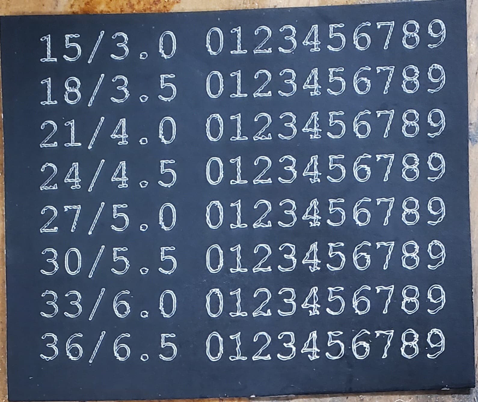
I’m trying to dial in my laser for engraving and noticed at small scale, my lines are wandering. The issue is a bit like backlash, and I am looking for any ideas that either fix the problem or any troubleshooting steps I can take to track the problem down. Here is my original test. The numbers at the beginning of each line are the speed in mm/s and the laser power used.
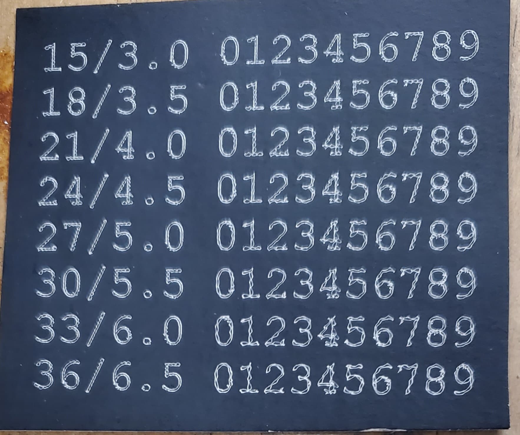
These letters are about 5mm high. I thought this might be some sort of vibration from moving around the mass of the Z axis and core so quickly. I replaced the Z axis with a plastic version (manual so no stepper) removing over 2 lbs. from the core. I also added some blocks to make my enclosure more stable. Here is the result:
I don’t see any improvement. The softness is my photo, not the engraving. I found just a bit of play in the Z axis and eliminated it and ran the test a third time:
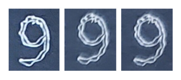
Again, to me, no improvement. What is most puzzling to me is that it seems to fail in a repeatable/predictable way. For example, take a look at the ‘9’ on the end of the middle line from all three runs:
I can hardly tell the difference between run 2 and run 3. I went back to the cards to make sure I had not made a mistake and posted the same photo twice.
Good idea, but didn’t solve the problem. I thumbed the belts and checked the grub screws before posting. The belts seemed fine, but I’ve never seen a test for correct belt tension. So, I tightened the belts a bit, mounted the stock in a different place on the spoilboard, and ran the test again. No improvement, and the motion matches the last couple of tries.
Bummer. I really wanted to tell you to check your grub screws!
I don’t really see much different in the speeds, and you’re not flying. You could try reducing the acceleration. But this feels like a mechanical thing to me.
Let me just dump some stuff you could try:
Jamie’s test pattern generator draws a ruler in one direction and then comes back the other way. Which is great for backlash. You would have to add in some laser power settings: Test Pattern Generator
Make sure there isn’t any numerical errors in the gcode. Look at it in ncviewer or something. I haven’t seen that many errors.
Toggle using arcs. Either turn them off or on to see if that makes a difference.
If it is backlash, it looks very small. Can you push the tip of the laser and see where it moves? You’re not interested in the flex. It would have to move 0.5mm or so with almost no resistance. This test can drive you bananas, because you will see things that don’t exist. But maybe you can find something that matches other evidence.
Reduce the acceleration and maybe the jerk. Just half it, or quarter it and see if it makes a difference.
You’ve probably already made sure the tubes were clean, the bearings are moving smoothly, the belts aren’t stretched somewhere (like the fiberglass broke), the motor mount screws aren’t loose, stuff like that.
Tricky issue. I hope we can figure it out. It is gnawing on my brain already.
I’d increased the acceleration as part of trying to get tile burning faster. Currently a 4" x 4" takes two hours. When I went back to the V1 firmware acceleration settings, the problem went away. So, thank you for the suggestion to reduce acceleration. That leaves a number of open questions, and a whole bunch of tests to be run.
WRT acceleration, given the greater mass of the machine MPCNC (compared to a 3D printer), I’d always assumed I see artifacts from machine movement as I increased speed and acceleration. But, these artifacts seem to be entirely driven by Marlin settings. I know that 3D printers, running Marlin use substantially higher acceleration than the MPCNC, so there must be “magic” combinations of Marlin settings for higher acceleration, because the inaccuracy in my original tests would clearly show in 3D prints.
That was a crazy read. I had ideas, saw them posted and boom you found the fix.
So because we have a larger moving mass than a 3D printer we will get ringing sooner. You could use an acceleration test to find at what point you start to see nasty results. F=ma so it is linear you will be able to creep up on a good setting for your build. At this level though, everything comes into play. Rails, XY and Z lengths, belt tension.
What did you change the acceleration to that this was happening?
The other thing to look at is classic jerk, and junction deviation. You need these set really low. We have DEFAULT_MINIMUMFEEDRATE already set at zero. Junction deviation can be tricky and I never saw great results but I think it has improved since I really tested it. But you could also switch to classic jerk and tune that. What is going on is that your moves are so small they are not even being accelerated. If you tune the instantaneous jerk/JD super low you will be able to tune accels a bit higher.
Or, I hate to say to say it. Give GRBL a try. You have a rambo right?
I would be curious to see a zig zag pattern. One where you consistently took 90 degree turns, and the straight aways were long enough (like 3cm, maybe?) to get some good speed. I would expect it to “under steer” and then over correct (like a sine wave after each turn, but the magnitude gets smaller). That should give you pretty consistent ringing.
If you didn’t see that, even with your higher acceleration settings, then it may be some kind of computational error. I know Jamie and Ryan were seeing strange stuff like that going really fast with arcs on or off when they were testing lasers and arcs.
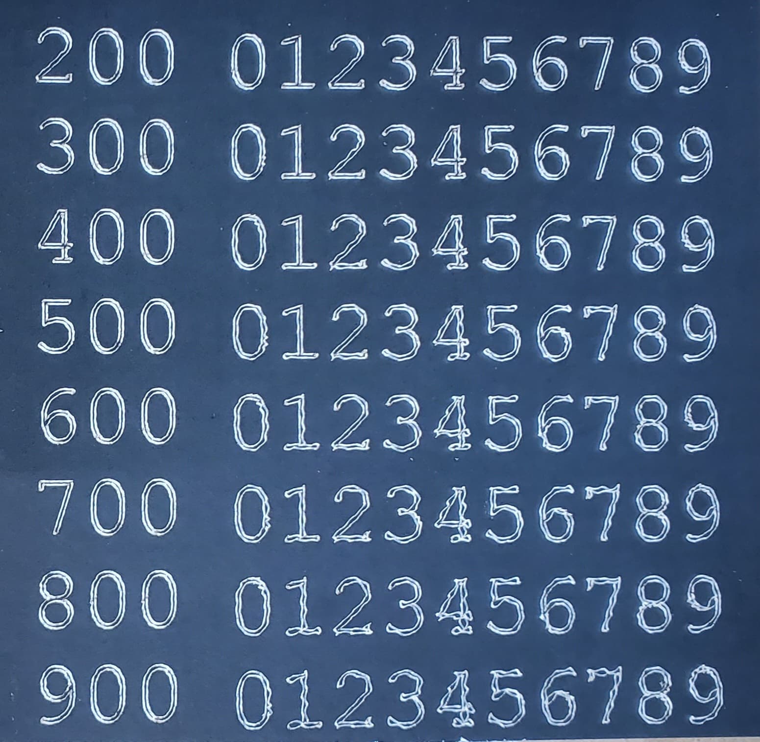
I tracked the problem down and now I think I understand it. This is what I get for playing with things I don’t understand. Acceleration, jerk, junction deviation are all new to me, and I only have a vague idea of what they do and how they fit together. I’ve been trying to increase my engraving speed, and I’ve gradually moved up my acceleration from the original 180 to 1200. But the problem wasn’t the max acceleration. I was playing with both M201 and M204 g-codes, and I increased the values in tandem. The issue is that I used M204 to set the starting acceleration too high.
In this test, the printing acceleration is set to 1000, and I increase the starting acceleration.
So, I assume that Marlin is fighting itself, wanting a lower acceleration but is forced to start high and come down.
So because we have a larger moving mass than a 3D printer we will get ringing sooner.
That is why I swapped in an all-plastic Z axis, but I see little in these tests that indicate I’m hitting any serious ringing issues.
But you could also switch to classic jerk and tune that. What is going on is that your moves are so small they are not even being accelerated. If you tune the instantaneous jerk/JD super low you will be able to tune accels a bit higher.
Good to know, though ultimately messing with the acceleration was a bit of a boondoggle. Since a lot of engraving is just long, straight scan lines, acceleration only plays a minor role in the time it takes to engrave, say a 4" x 4" tile. Using Lightburn to simulate the time, jacking up the acceleration from 180 to 1200 only saved me 6 minutes on a 2 hour engraving job.
Or, I hate to say to say it. Give GRBL a try. You have a Rambo right?
What stopped me in the past is that I want a 1) wired solution that 2) does not involve putting my good laptop in a dirty and largely unsecured shop area. Does GRBL for Rambo support a display?
I am pretty sure you can adjust the Juction deviation on the /lcd. I would try setting it to you 500 line accel and lower the JD to see if that improves it.
Accel is hard to tune.
We use junction deviation to tell it when to even consider acceleration - eg if we go from 3mm/s to 5mm/s don’t bother even calculation an accel.
Then if an accel is triggered it gets smoothed out by the S curve acceleration so it is not a hard trapezoid.
MAX and Starting accel should be the same, I believe the terms are just mixed up in teh docs vs the firmware.
We also have another accel I can’t think of right now that was giving me horrible issues at high speeds during the LR3 testing.
It helps a little but we still have 4 steppers and 2 steel rails swinging around.
It is more about getting the machine to START moving smoothly to get rid of your artifacts. I only tuned the junction deviation for slow routers. You should tune it for fast movements. JD is when it will consider accelerating, so if this was set to high it would not even try to accel and just slam around at every corner. With tiny segments at high angle changes they might not even get going fast enough to trigger an accel. If you go too low though it will try to accel on tiny angle transitions and circles will get messed up.
Not yet but I have been working on the WIFI headless solution the last few days and just made some progress between our messages. Grbl tests 2022 - #80 by vicious1
It’s possible, if you have a mass hanging off a cantilever, that it could be vibrating primarily by rotating (tilting) and not purely lateral vibration. In this case, adding a counterweight could reduce the vibration even if the torsional stiffness is not increased.
Assuming you can identify the approximate center of the lower-than-ideal torsional stiffness, you would add the extra mass such that the center of mass of the assembly downstream from the joint is roughly centered near the joint. Meaning it should be centered in the Z axis, to handle accelerating in X/Y without wanting to tilt. There is no need to center the mass around the joint in X/Y if you don’t have high speed movements in Z. Then the lateral acceleration produces much less of a torque on the joint, and therefore less rotational vibration induced from lateral acceleration.
If the torsional deflection (tilt) is the primary source, then good balancing could produce a huge improvement in addition to whatever benefit is gained from going slower or with lower acceleration.
You could also experiment with raising the workpiece and raising the Z axis which would alter the balance of the Z axis around the joint, and it would also shorten the lever arm so a given amount of torsional vibration would produce smaller artifacts. These effects would be combined, so it might not be obvious which mechanism is producing the benefit (assuming there is a benefit).
Yeah with a laser it is tough. It will be most stable nearest the center of the two XY rails, but increase focal length magnifies any issues. So the best case is like you say, laser as high as possible with the focal length as short as possible. So work on a riser to get it as high as possible.
The other way to look at it is for raster images none of this really matters with overscan enabled and just slowing down for Vector stuff also solves it and you will not lose hardly any time.
While avoiding actual work, this topic popped up again, and I thought to myself: “Hey, what’s got two thumbs and is usually the source of any inaccuracy?”