Help! Lost GCODE data points? (not lost steps) Messed up milling

OK this may be a long one… I have tried a lot…

The short synopsis is: things start milling fine, then it goes on a detour, then gets right back on track. If it was losing stepper motor steps it would get back on track but shifted. This gets RIGHT back on track for a while then takes another detour. Then gets back on track.

Setup is MPCNC with RAMPS board and dual endstops and a touch plat for Z axis homing.
GCODE created by ESTLCAM. Was using repetier host but switched to using SD card to eliminate the PC (more on that later)

Did some wood milling when I first built the MPCNC and all seemed fine.

My first attempt at milling aluminum was nearly a success then things went pear shaped fast. 3/5 of the way through the mill just went the wrong way…

I thought I had figured out the issue to be a DRV8825 overheat issue and the Y axis drivers stopped and it just kept moving in the X direction. Lowered the drive reference and reran the same GCODE off the same SD card and no issues. The job finished and the part looked as expected.

Here was my first attempt. Since it was my very first attempt I was babysitting it and as soon as it went for the little detour I hit reset fast.

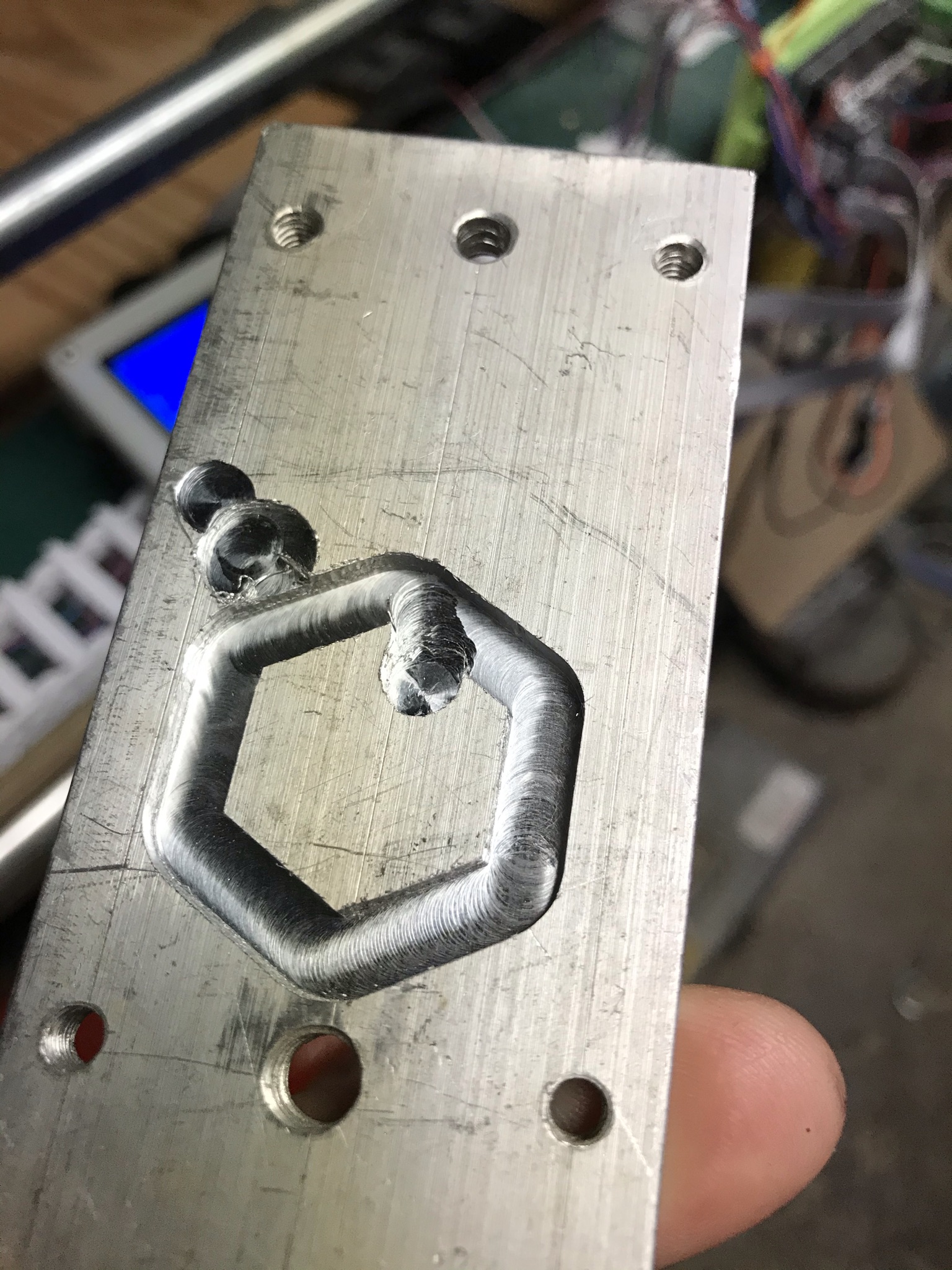
After lowering the DRV8825 drive current here is the rerun

Exactly what I was expecting, a hexagon not all the way through. It was literally the same GCODE from the same file on the same SD card. Had not been changed. Worked… I was on cloud 9. Feeling pretty confident.

So I moved on to the task at hand, two parts for a boat bracket.

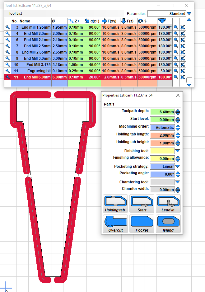
Created in TinkerCAD, exported as SVG and imported into ESTLCAM and saved as a project. It is still a pretty simple part. 6.5mm cutout with holding tabs. That’s it. Running at a slow feed and only .1mm per pass depth of cut. Pretty conservative. Here is what the toolpath looks like in ESTLCAM

I think this image actually contains pretty much the whole part story… not a complex part

I watched the ESTLCAM simulation. Nothing looked odd there.

So I set up my aluminum stock and started the job. After a few laps around things went pear shaped for no reason I could think of. Kind of messed up the stock so I decided to simply rerun the same job on the same stock. This time it didn’t plow into the work where it did the last time. kept going properly. Somewhere about 3mm depth of cut it stopped moving in the Z direction. Just kept doing the path but no Z change. Hmmm… Once I figured out Z had stopped moving, I reran AGAIN. Same GCODE. Same SD card. I know, insanity is doing the same thing and expecting a different result… but I GOT a different result… Since 3mm down is like 30 laps, I used the speed knob on the LCD to crank it up to 500% to do fast laps to get down to where the last fail was, then slowed it to like 50% to see if that was the issue. It went quite a ways then at some point went the wrong way.

I was running out of things to try so I decided maybe this was a hardware issue with the mega2560/RAMPS boards. I have spares of both. Wrote the exact same firmware that was on the original to the spare. The only things I did not have spares of were the DRV8825 driver boards. I swapped them from old to new. (spares of those are on their way…). I could have used the A4988 driver boards I had but I wanted to use the EXACT same firmware as the original. So new mega3560 board. New RAMPS board. Old DRV8825. Old LCD/SD card reader.

Got that up and running and ran it and things again went pear shaped. Second run and pear shaped in a different spot. When I am milling aluminum and things go bad I hit the reset pretty quick so I cannot tell what would have happened if I had let it go…

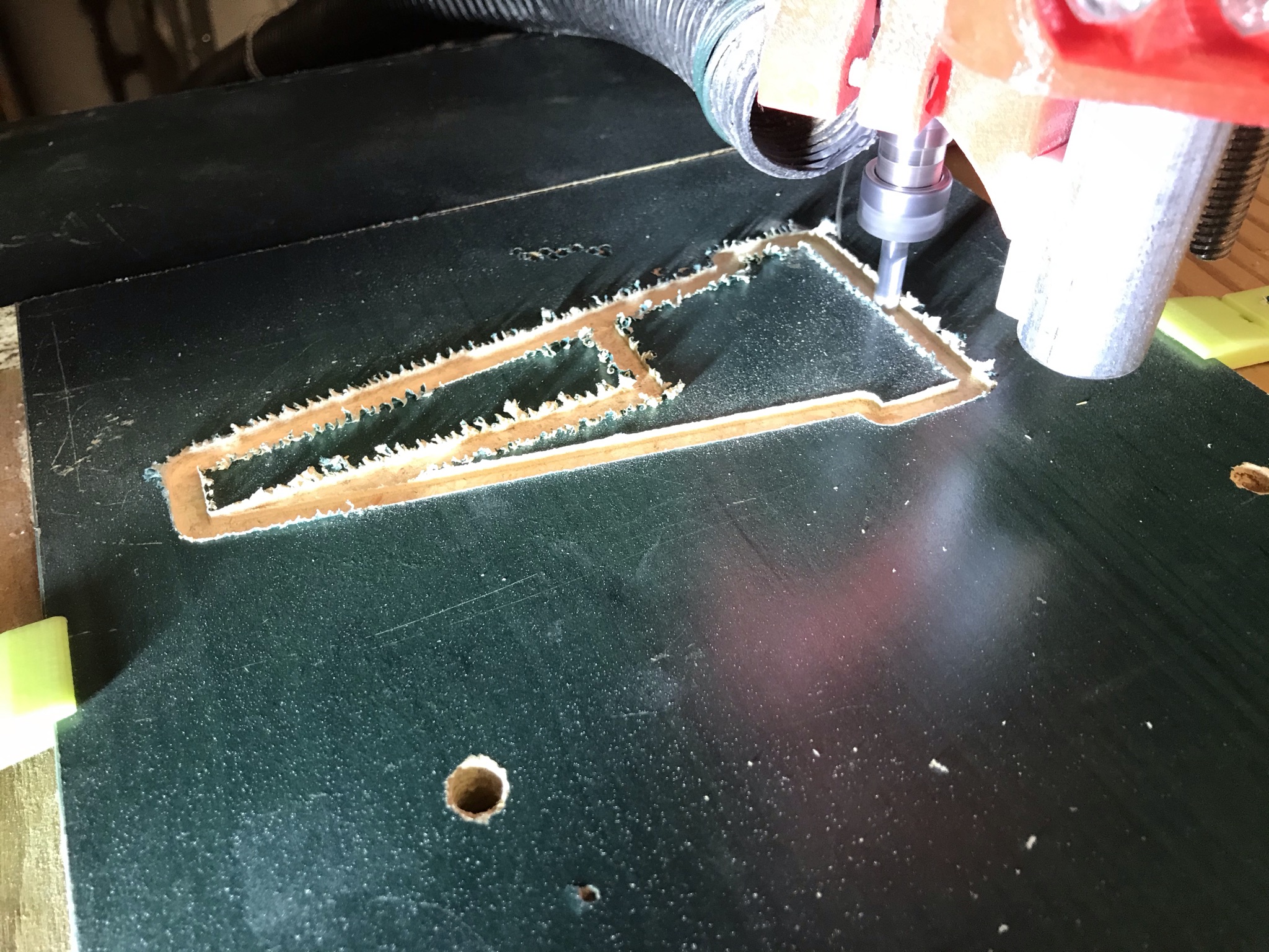
So I decided time for a piece of wood.

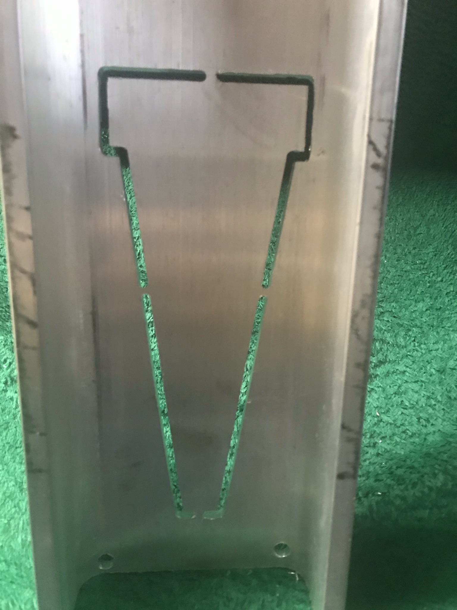
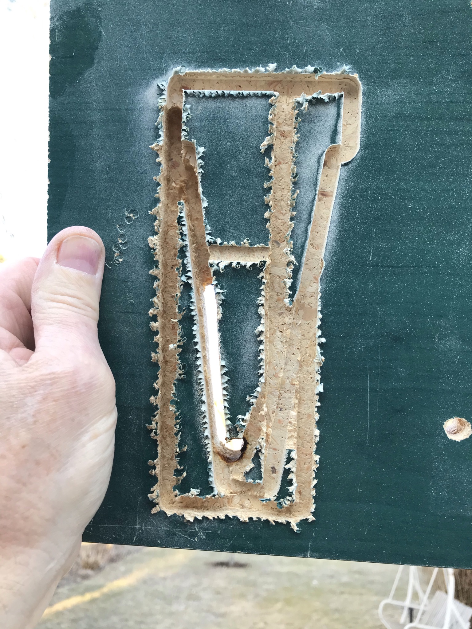
Mounted a scrap board and ran the job. When things went bad I let it run… THAT was interesting. The two round holes in the wood in the lower area were there already, scrap wood, the CNC did not do those…

You can see the part outline and the little “detour” it took on one pass. But in wood I just let it go and lo and behold it went back on track and carried on. Since this was wood, the slow feed rate was going to be killer long so I had used the LCD speed control to go 200% which is what it was running at when it failed.

I had this theory that playing with the speed may have CAUSED the issue… so I left it as was (didn’t touch it again, still at 200%) and let it run. It messed up a while later, plowed through some thick stock BUT GOT BACK ON PATH.

The way it kept getting back on path told me its not the steppers losing steps… its losing GCODE commands then getting the next few and its back on track.

It messed up a few more times and eventually I had to hit reset because it messed up in the Z direction finally and plowed through the stock and was heading for the floor but ran out of cutting edge on the end mill and started smoking the wood and the steppers were unhappy trying to push a smooth rotating shaft through 19mm of particleboard.

So… same GCODE file every time.
Full change of controller hardware (mega2560 and RAMPS board)
Same firmware on both.
Random drops of GCODE it feels like.

Sort of running out of ideas…

Things I am pondering…
Marlin Firmware: Am I having trouble reading SD card?
In the firmware I have enabled the following in the SD Card support section of configuration.h:
#define SPI_SPEED SPI_HALF_SPEED
I have the SD card set at half speed (because that’s the way its set on my 3D printer so I decided maybe that was conservative so I did the same. maybe I should try slower? Maybe I should enable CRC as in uncomment //#define SD_CHECK_AND_RETRY? I am not seeing any errors but not sure how they might appear.

Other than those I have zero thoughts and I am hoping the vast experience of this forum can shed some light and make me wiser.

Here are my Marlin config files if anybody cares.
Marlin_Configs.zip (75.5 KB)

We have seen some cases where the machine would fo fine and then go straight to something like Y=0 and then return and be happy again. Driving right through good workpieces. I don’t remember a satisfactory result, but we were thinking it was some kind of emi noise or file reading error. Something like G1 X100 Y100 got turned into G1 X100 Y1. I remember trying things like shorter lcd cables or grounding everything and something worked.

We have configurations for Marlin i. MarlinBuilder releases. You might try the v510 and make sure it isn’t something covered there. That is a bit of a selfish recommendation, because it would help me know if this problem exists in our configs or not.

Thanks @jeffeb3 for the tips. I’ll take anything right now.

Just to clarify the configs you are referring to…

I am running the V1 Marlin not stock Marlin. I think I recall seeing a 509 somewhere in the version or code somewhere. V510 is the same code with different configuration settings? Or is this a different Marlin build with the same config settings or new Marlin and new config settings?

So one thing that I am doing that may be a factor… Arduino mega2560 power… it comes from the same 12V power supply that powers the steppers. There is regulation on the mega2560 board but maybe stepper movement and load on the steppers is causing power supply noise. I will run the mega2560 from a separate 12V adapter and see if that changes anything.

Do you have any issue with the test crown? If the Gcode is not formatted right things like this can happen.

If my crown gcode works fine upload some of your so we can see if it is funky.

Just reran the GCODE with the Arduino getting power from its own separate 12V power supply. Still took a detour.

On a random shot just running it again using a new SD card… The one I was using was a good quality Silicon Power 16GB micro SD card in an adapter. I formatted some brand X 8GB full sized SD card I had. Its 1 hour into the job with no issues… but that is a far cry from finished with no issues… not even half way.

Anyway, I am in the middle of that and not going to interrupt to try the crown GCODE at this stage but I have uploaded my GCODE from ESTLCAM. Its pretty simple GCODE… nothing obvious in it… and the random nature of the failures leads me to believe its not the GCODE… but I will try the crown when this finishes (or fails…)

MasterCraft ProSport 205 Swim Platform Bracket part.gcode (47.0 KB)

Well your gcode does look fine, so that at least eliminates that as a possible source for the most part.

If you have a vac hose they can cause a ton of static and that can cause issues. Some people have to ground them.

I do have a vac hose to a small shop vac. I will look at that and see what I can do about making a grounded adapter for the MPCNC end of the hose.

Getting bored watching this thing cut wood at the speeds I had programmed for aluminum so just rolled it up to 400% so it finishes before I expire. No issues so far since changing the SD card… hmmm… but I have gotten prematurely over confident before and that usually results in at best a damaged ego and at worst a hole in the waste board or an end mill that doesn’t love me anymore… (there is a reason I am using a 6mm end mill… they don’t break… but I nearly started a fire in the wood when the Z plunged deep and the non cutting shaft was rubbing against the wood!!)

Well just finished without issues… and literally the only thing I changed was the SD card.

Ran a Flash Drive test program on the original micro SD card on my PC. No issues with a full 16GB write/read.

I’ve got nothing.

Tomorrow I will try again on aluminum and see how far I get!

A lot of the changes were for other boards, or the laser config. There is a setting changed for sd spi speed, IIRC.

So one thing about the 2.0.7.2 code for 8 bit boards like the RAMPS/mega2560 setup is that in the configuration.h if you enable the spindle AND you enable RPM instead of PWM255 mode, setting spindle speed doesn’t work. This is related to a bug in the code where the spindle power returns an incorrect value as I mentioned in another thread post. Had to add a float operative to the return line in
Marlin\src\feature\spindle_laser.h
line reads
return unitPower ? round(100 * (cpwr - SPEED_POWER_FLOOR) / (SPEED_POWER_MAX - SPEED_POWER_FLOOR)) : 0;

the following works

return unitPower ? round(100 * float (cpwr - SPEED_POWER_FLOOR) / (SPEED_POWER_MAX - SPEED_POWER_FLOOR)) : 0;

But I haven’t tested that on anything but RAMPS/mega2560 boards…

Looking at the configuration.h settings in the V510 code related to SPI speed I see that by default now the half speed define is uncommented (which I already have in my code) but I also see that maybe a global search and replace was used as I see:
#define SPI_SPEED SPI_HALF_SPEED

it originally read

//#define SPI_SPEED SPI_HALF_SPEED
//#define SPI_SPEED SPI_QUARTER_SPEED
//#define SPI_SPEED SPI_EIGHTH_SPEED

Not sure why you would get rid of the quarter and eight speed options in there.

So yes there are changes in V510 for SD SPI speed, but they are changes I already have in my configuration.h so that doesn’t seem to be my issue.

So last night I ran the GCODE off a new SD card. Ran to completion with no detours off into the part. First successful complete process in wood instead of aluminum.

Was going to run in aluminum this morning but opted for a more conservative approach and reran it on the wood and feeling brave ran it at 500% speed since I was literally using the same wood as last night still mounted on the machine so it wasn’t actually MILLING unless it went astray into the part… its over half way through and hasn’t missed a beat. Update: finished 100%, no issues…

After 6 failures in aluminum and multiple failures in wood in a row, having two complete success runs in a row it is looking pretty positive. The only change is the SD card. It is the same GCODE file (March 17 date). The old SD card passed a full 16GB write read test on the PC… so I have no idea WHY changing the SD card made a different. If it had been a repeatable error in the same spot in the toolpath I would have understood better but this random nature leaves me scratching my head.

I have enough courage now to try aluminum again…

1 Like

A funny thing to do with the SD cads is always have your files at least one folder deep. For whatever reason it is very noticeably faster when selecting files on the screen so I assume it also works better when running as well.

2 Likes

This is just because the scripts are kinda dumb. It doesn’t make any difference in the code, and I know it looks funny, but the target for this is a either someone who won’t edit it (for maybe 75%) amd as a baseline to start editing from.

Things took an interesting turn tonight… in a positive direction for a change… but that was after about 8 turns in a negative direction…

I started this post 2 hours ago with the line “Still not out of the woods” but as I wrote the post I had a thought… I think it falls under the KISS (Keep It Simple Stupid) approach or maybe something teachers had drilled into me forever “go back to first principles”

I am running V510 code now and I am 4.8mm deep in a 6.4mm cut in aluminum and it is following the GCODE toolpath properly so far. I am not calling it a success YET but its WAY close than I have ever been…

And there are other issues such as a lot of chatter and because I have been testing on the same piece of aluminum for all my failures it looks like a labyrinth of toolpaths… but it appears I have narrowed the issue down.

Marlin issue…

Well Marlin with a little help from me issue…

And I am going to have to do a bunch more testing to determine exactly where the Marlin issue is, but I appear to have gone far enough back to first principles that I have a working marlin on RAMPS/mega2560… read on for the details so far… if I take long enough to write this maybe the part will finish…

After thinking it was an SD card issue and I had two good runs in wood with a new SD card, I tried again in aluminum… and I had failures… many… and this time I didn’t have the same brutal detours as before, but I did have what felt like lost steps. Whole thing shifted… then shifted back… it would get off track but follow the shape, then get back on track. So I left it for a couple of days while I pondered why. It didn’t seem like I had binding. I wasn’t hearing anything really rude sounding with the motors or the spindle or the mill. Why was I losing steps? I had checked Vref on DRV8825. Things were not overheating with a fan on the RAMPS board. I could leave a finger on the DRV8825 heat sink comfortably.

In hindsight I don’t think I was having lost steps… I think I was still having the same issue but it was appearing differently. Random failures can present in random ways…

I now think the issue I was having was related to spindle control, and may be related to me enabling RPM mode and “fixing” a bug in Marlin on 8 bit boards… here is why I think this is the case.

Initially I still suspected the SD card data was getting corrupted. My Raprap graphic LCD with SD card reader has been common the whole time, even when I changed mega2560/RAMPS. I thought maybe it was the SD READER not the card… I had downloaded the V510 code and run it on my spare RAMPS/mega2560 board as a test and my spare board just has a 2x20LCD with SD reader. So I thought if the issue is the SD reader, lets used the 4x20LCD/SD reader on the MPCNC and see if that fixes this issue. So I compiled the code and flashed the MPCNC and the spindle didn’t spin when I started the job…

Oops, I had forgotten to enable the spindle in Configuration_adv.h and forgot to set it to RPM mode. I did that and tried again and still had the same issues as V509.

Still thinking it may be an SD error of some form I decided to use Repetier Host to send the file and eliminate the SD card altogether. Same issue… What???

While pondering this latest failure I was also typing the previous version of this post and I was going to mention to @jeffeb3 that the V510 code had the #define for RPM mode removed…

That’s when the lightbulb came on.

Maybe the issue is somehow related to the RPM setting and the “bug” in Marlin that I “fixed” based on a github code fix I read related to this.

So I went back to first principles…

I took the V1CNC dual endstop V510 code and ONLY changed the Configuration.h for the text mode 4x20LCD and used Repetier host to send the file. No spindle control (I manually set spindle speed). No RPM mode. Just the most basic form of the dual endstop code.

And I am now 5.8mm deep in the 6.4mm cut…

So… from here forward its baby steps…

First I enable spindle control and leave it using PWM255 speed and just edit my tools in ESTLCAM to set RPM to values from 0 to 255 and see if things still work. If they do, then the issue comes down to the RPM mode…

My guess at this point is that using RPM mode is the issue on the 8 bit board. Adding the float operator in the spindle control feature section of code may make the spindle part work… but I suspect that there is a large number overflow still happening elsewhere in the code that is corrupting things and causing these random failures.

I will report back when I have enabled PWM255 and run another test… may be a while…

Success…
(would be much nicer if the other side wasn’t the previously mentioned labyrinth of failed cuts… sigh…)

3 Likes

If the motors skip steps, the drivers and ramps have no idea. So they can’t get back on track.

I can imagine this being a less beaten path feature in Marlin. So it does make sense that it may be the culprit. Maybe this should be brought up in the Marlin project issues. Computing the spindle rpm should be pretty quick for even an 8 bit board. And it shouldn’t happen often. But maybe that is the bug.

My understanding is that one of the differences between using Marlin’s Spindle and Laser PWM control is that there is a delay built in when spindle speed changes to allow the spindle to get to the commanded speed, whereas laser intensity changes are considered instantaneous. I use Marlin on my 3d printer, but grbl on my MPCNC and K40 laser, so I haven’t done any digging in to the code, but if it is re-calculating (or even just rechecking) the spindle speed on occasion, maybe that delay is being honored even if there’s no real spindle speed change.

Like I said, haven’t dug into this element of Marlin code at all, just a “Might that be…” that occurred to me.

The bright side of this is the V510 code seems to compile and work as is on the RAMPS board. This was a pretty good test of it in CNC mode.

I put my full graphic LCD back in place for my currently cutting test (I need two of these parts and that first successful one above is no good on the other side where past failures line!!) and I used AVRDUDE to load the V1CNC Ramps Dual 510 firmware.hex code onto my RAMPS board and 2 laps in on the same GCODE I saw a deviation for one lap then at lap 5 it cut straight across my part. So I won’t be using V510 firmware.hex… About to recompile and load from source with graphic LCD enabled as the only change from last night successful run with 4x20 text LCD code

1 Like

And once again a step backwards…

Tried again with compiled firmware using graphic LCD… didn’t even enable custom bootscreen…

Failed…

Thats when I realized that for this latest test (compiled) and for the last test (firmware.hex) I was using SD card for the GCODE…

So I am trying again using Repetier host…

Still failed…

Going back to 4x20 LCD compiled using Repetier host just to see if I can reproduce my success of last night…

Only a little frustrating…

Sorry to be one jumping in last minute with my 2 cents, and I’m just making a wild hunch, but working well on wood but not on aluminum, my guess would be that the steppers are maybe being driven too hard and losing steps? I would try light cuts on wood several more times, then very light cuts on aluminum and increase the depth of cut or stepover on a junk piece of aluminum until you see some failure, and monitor the temperature of the steppers as well. I am also very wary about using circle records in my gcode until I know for sure that the controller is ok with the G02 and G03 commands and settings ( setting like full circle or quadrant, ijk or start end point settings.) I’ve seen some very strange things happen when cnc machines make very small circular g02 and g03 motions.

Jumping in last minute is when you jump in when I have the problem solved… Still feels like first quarter of the game to me…

I confess to partial defeat… My last test was a fail. Plain V510 code with 4x20LCD using repetier host to send so no SD card. Did a few laps then shifted. This was like lost steps. Shift up in the Y direction.

But I needed the part, had nearly exhausted my aluminum, so I did one lap of the part on the aluminum using the MPCNC then used my bandsaw to cut the part out following that path. Felt rude but now I have more time to debug the issue(s) without needing results.

My part is simple and I will continue to test with simple parts until I get this resolved, so there are no curves at all in this toolpath. No G02 G03 at all. I even looked again at the GCODE to make sure. None.

I will do some wood cutting and see if that all plays nicely and see if I can figure this out. Will probably take a while before I respond to this thread again while I test and see if I can get enough data points to narrow it down.