Help with endstops, of how low can you go?

So just how accurate can you get a MPCNC and most importantly, how do you do it? Initially when I set up my end stops I used a 0.030" drill bit with 1/8 shank to poke little holes in paper at each corner and then measured corner to corner distance. That got me real close or about as close as I can see to center the tiny holes to a tape measure. My bed is 15" x 15". Turns out that is about 0.030" accurate or llittle ess than a mm. This seemed much more accurate than I ended up with trying to draw boxes with fine tip pens.

So I decided to take this to the next level. I started cutting 5" circles in pvc board, inserting a bearing, and measuring runout with a dial indicator. So far it seems like an excellent way to measure, but I just can’t get below 0.015" error. When I make a small adjustment it jumps to 0.030 error again.

What makes this even more difficult is I can’t tell what needs to be adjusted to get my desired outcome. X stop, y stop, ot both. I thought this was a simple thing but it seems very complex. Anyone conquer this?


Are you using dual end stops and making adjustments with M666, or are you making physical changes?

If physical, how are you moving the end stop or trigger? I’d suggest a screw (with a locking nut) that you can fine tune to hit the end stop plunger for physical adjustments. The finer the threads on that screw, the more control you’ll have.

I believe there are instruction in the Docs section for dialing in with the M666 parameter, but as I recall it boiled down to “Measure the diagonals, make a change to the M666 setting on one axis, measure the diagonals again. If the diagonals are closer in length, make another M666 move in the same direction. If not move M666 the other way (or adjust the other axis). Stop when you get to a point that makes you happy.” My board doesn’t support dual end stops, so I haven’t been through that procedure myself, so can’t serve as a more specific guide.

1 Like

A screw adjustable endstop is a stellar idea!

That doesn’t solve my problem, but would be a sweet upgrade. I will post some sketches of what I “think” is going on. I am moving endstops around now because I didn’t have much success with the M commands. But the issue is not so much a finer adjustment is needed, but rather making an adjustment and predicting what will happen. And the other problem is trying to site the diagonals with better than 0.75mm accuracy.

1 Like

I’d try by starting with a Rectangle whose diagonals fit within the measurement envelope of your calipers. Once you’ve got that dialed in it shouldn’t take much of an adjustment to fine tune for the largest rectangle that will fit in the build area.

Also, remember that it’s the difference between the diagonals that matters, not their absolute length. Transcribe one diagonal’s length on to some sort of (non stretching) story stick and you can put it next to the other and easily measure the difference with the caliper.

1 Like

0.381mm is pretty good, and on material that thick things like tram come into play.

How much more do you need? I am not a fan of chasing zero’s just to chase them. If you need a specific number, we can dig it a bit but it starts getting fiddly real quick.

1 Like

Have you checked all the basics like collet and endmill runout?

A fine tip pen and doing this will get your machine very very dialed in, and let us know what your starting point is before adding a load.

That low and high spot on your wheel must mean something, but I can not put together a scenario that would do that. They are about 90 degrees apart, but not on either axis.

I also strongly recommend a “shakedown” moving the machine throughout the movement envelope and then physically checking for anything that may have worked itself loose, like grub screws in the pulleys or wires at risk of snagging on something, before going for the final end stop tuning.

1 Like

Thanks for feedback. My machine is very tight and seems to be very repeatable or I would never have gotten this far. Poking tiny pinholes in paper got me much closer than pen lines. And it will repeat the pin holes without any changes. So again, with a little luck I can dial it in with 300x300mm paper to the best I can distinguish with a tape rule. I was not very successful using a caliper on a 5" box because it was less than half the error and also hard to read even with calipers. That is when I came up with the perfect circle idea and measuring with dial indicators. How much error can I live with? Not sure exactly, less than .25mm desired, but 0.1mm would be great! No problem, right?

So the attached sketch is what I “think” is going on with the X and Y offsets. If everything is symmetric, then an X and Y adjustment can get things very close by eyeball. When X or Y are not symmetric, some weird things happen and they are not so easy to see when drawing lines. When I started cutting the circles I began seeing this. Going by the sketch, if you have a stretched box like the red line, A cut circle should have 1 high spot, and 2 low spots and something that looks like a lower high spot. I achieved this a couple times. In that case it would be symmetric and equal adjustment on X and Y should bring it in. So what happens when you adjust 1 axis more than the other axis? So my theory is if X and Y are not symmetric, something has to slip. In my circle it shows up as top left to bottom right corner errors not even. 1 big high spot and 1 big low spot on my circle. If it is off enough, I get a flat spot in the circle. That is why I think it slips somehow. And the most difficult thing is once I am that level of error, I do not know which end stop to adjust. That is why I drew it out to try and understand.

If you are milling a hole, and milling the circle. Is the error adding, multiplying or subtracting.

If you are measuring .25mm error you might actually be at .125mm or less…or way more.

This is kind of why chasing the zero’s is tough. If you can’t measure it, why worry? Do you have a real world part you can make and measure to see if it meets your real world needs. If you can not measure the error in a 5x5 square, is that not good enough?

I swear I am not trying to be difficult, I am genuinely curious.

With your picture in mind, you should also have a second high at least and possibly another low, depending on what is going on with your bearing cutout. That is why I am not sure how only two spots would happen on your disk.

Measuring the OD of your circle what does it look like on axis and at 45 degrees?

I am trying to make some rotating parts. And that is how I found my initial error, spinning them with a dial indicator. But they were messed up due to my rails (and end stops) moving back and forth. So I when I reset everything back by sight, I decided to cut some circles to see if that was “close enough” and found the best I can do is about the 0.38mm out of round on a 150mm circle. I assure you I am not just chasing 0 and it seems this can be reduced if I just knew which knob to turn… I think I can do better, but don’t know how to adjust it without guessing. The sketch shows exaggerated conditions, in reality when you are less than a mm off on each of the box dimensions, it is very difficult to determine what to do next. If I could draw a 800-1000mm box I think I would be there but my bed is not big enough.

So I once I moved to spinning my cut circles the error really shows up clearly, no squinting… I started making small random adjustments but only made things worse. I could not really correlate the changes to the circle out of round findings. So I drew the sketch above and now I think it might make sense what I was seeing in the circles. I wanted to bounce that off the community to see if makes sense, and in case Ryan says it can not be done… So next time I get to the shop I will re-evalluate my circles and again try to correlate X and Y change to results. More to come…

2 Likes

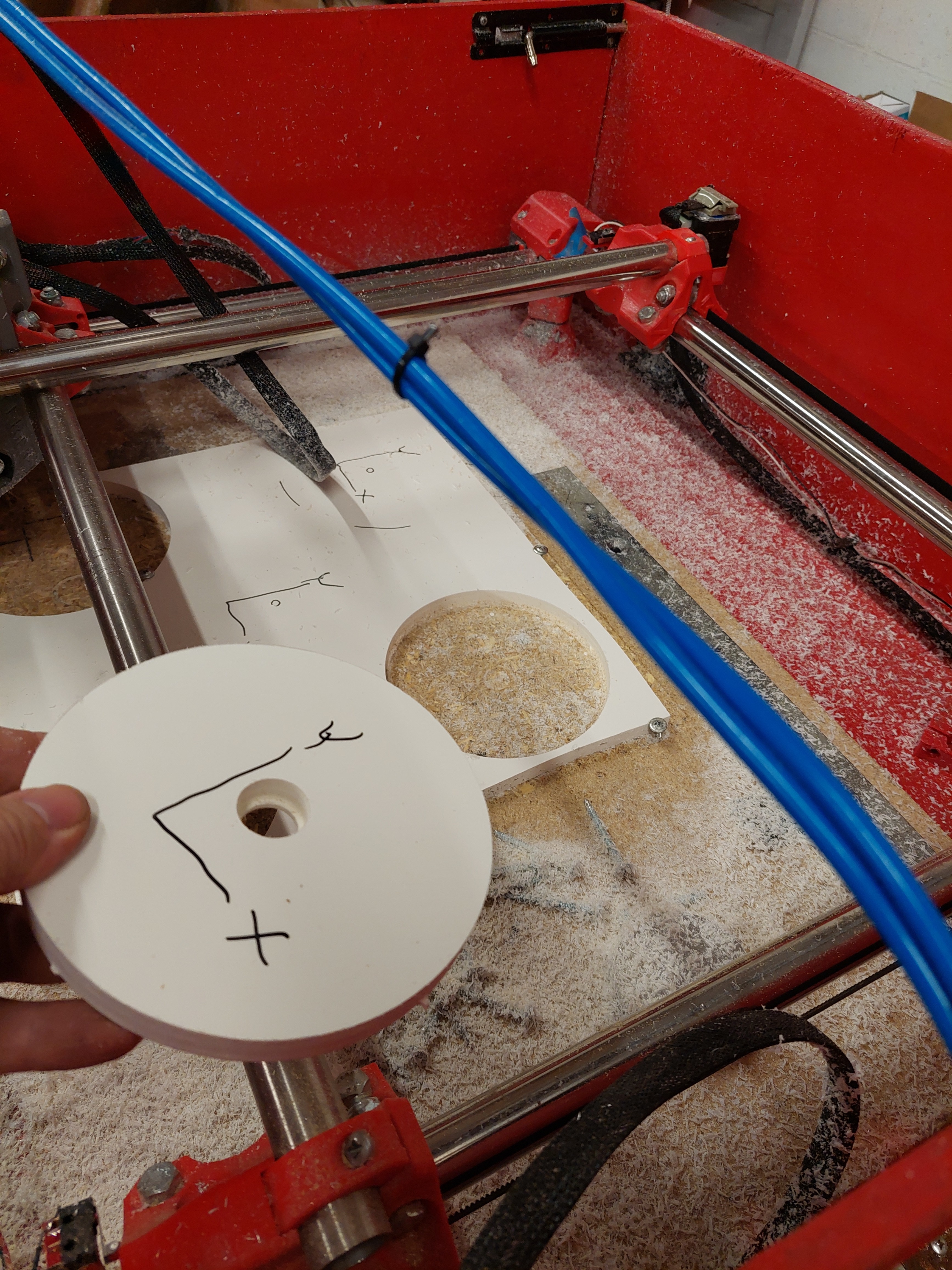
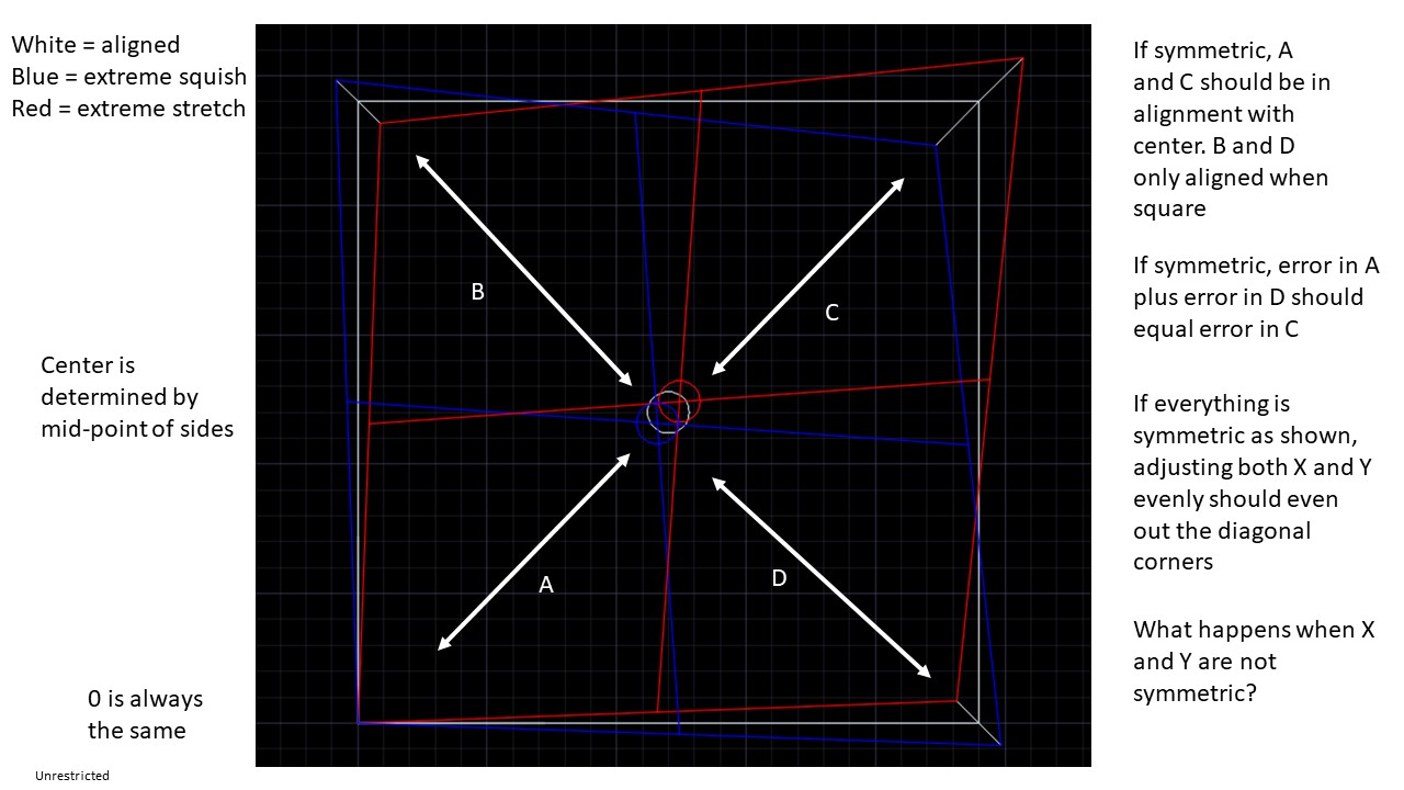
I am not saying it can not be done just anything under 1mm is extremely difficult to point a finger at. we have dimensional errors, and squaring issues. Square is simple to adjust, dimension is a hard road. Some people have just had bad collets out of the box, but that was a dimensional thing. Square test parts would really help me, to help you, and you need to be able to measure them to the accuracy you require. A circle will work but you are throwing away the extremes but if you accurately mark the axis we can make full use of your calipers at least.

If you cut a square(or circle), or draw one, you can measure each axis and each diagonal. You can cut or draw a ~380mm square on your machine. That gives you ~537 diagonals, and with that you are measuring the difference between them. Again, or a accurately marked circle.

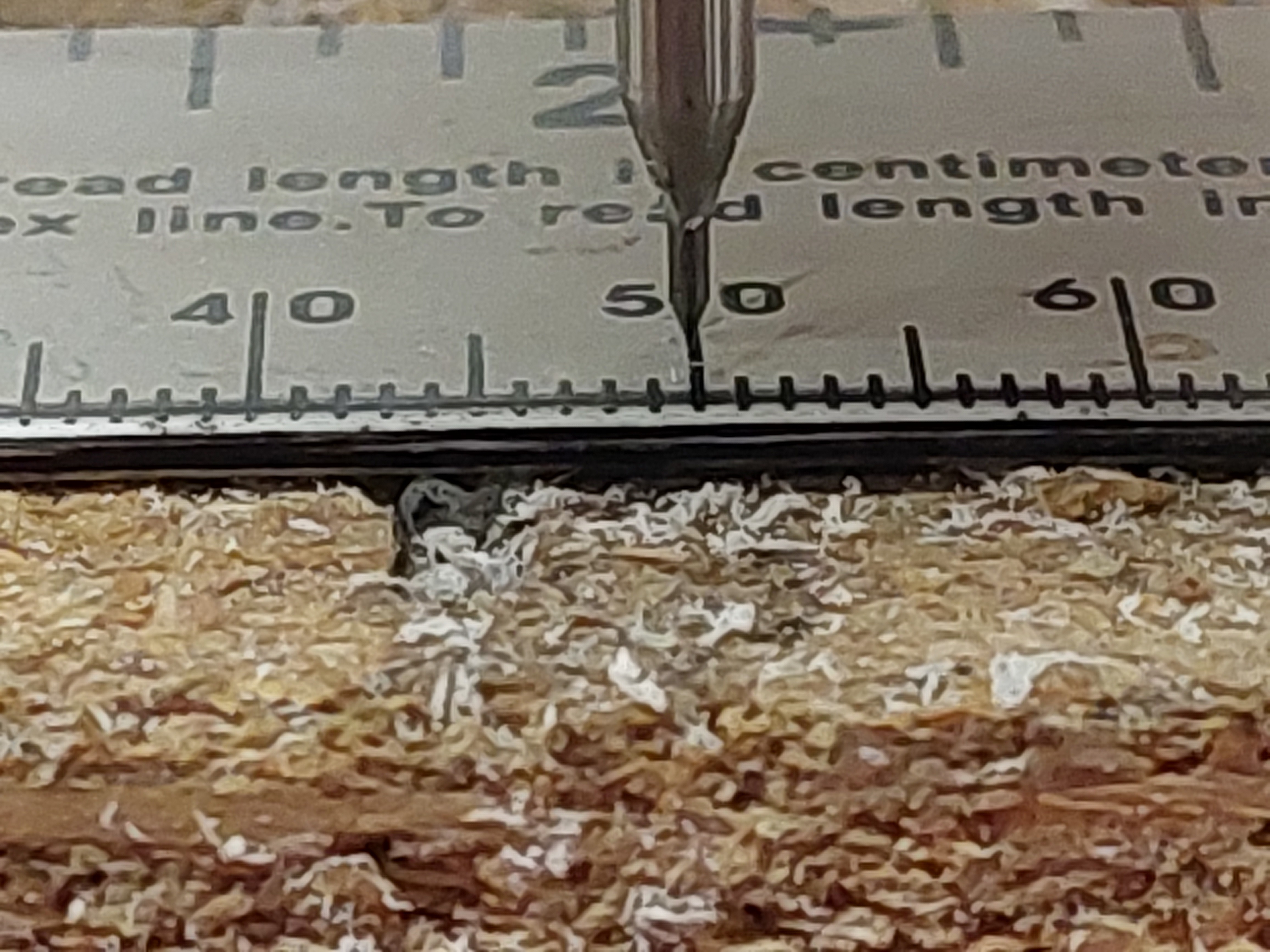
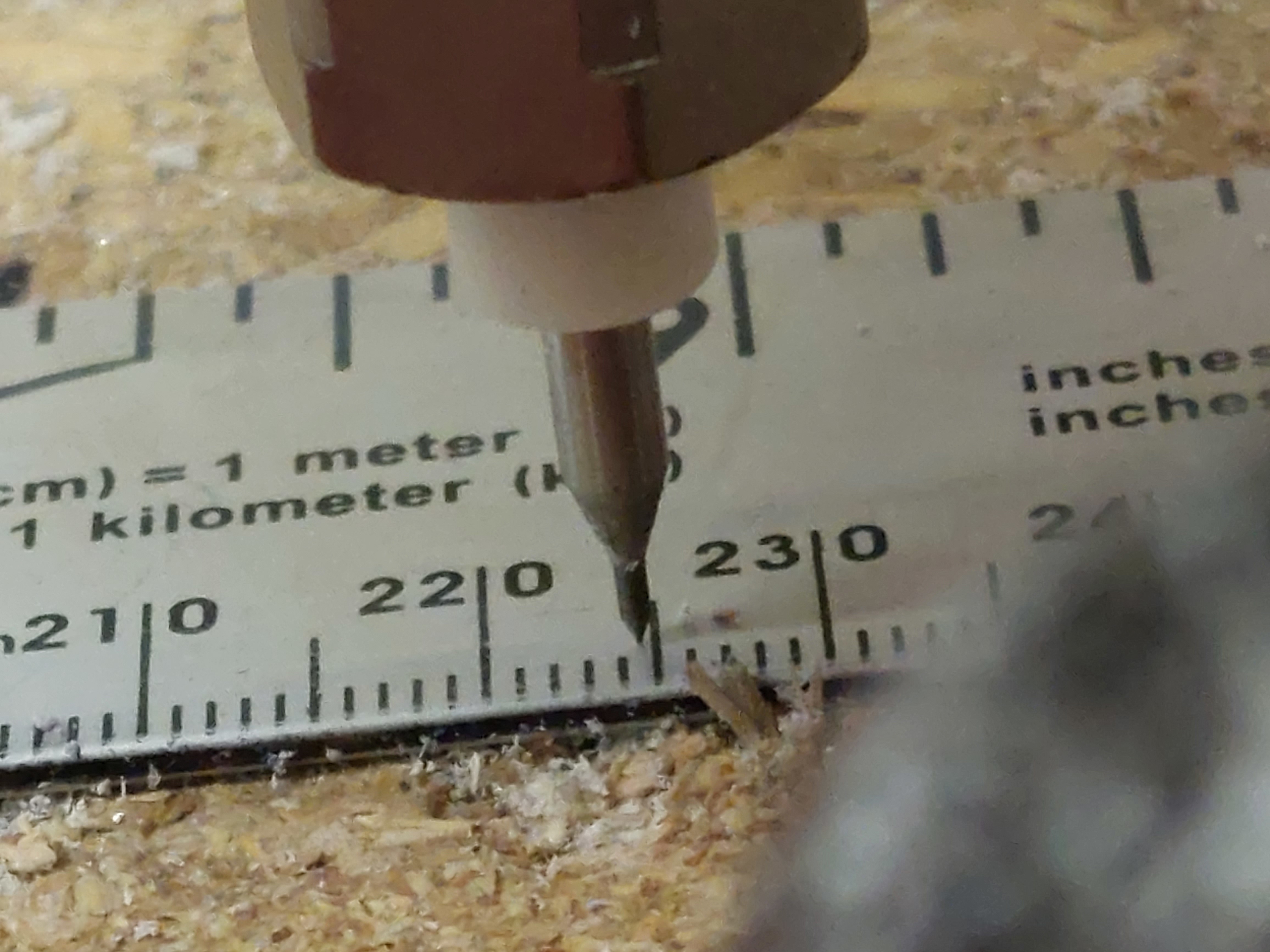
So a standard caliper is accurate to about 0.01mm or 0.0005". So in a perfect world you could get ±0.01 over 537mm, at best but most people only have a 150-200mm caliper.

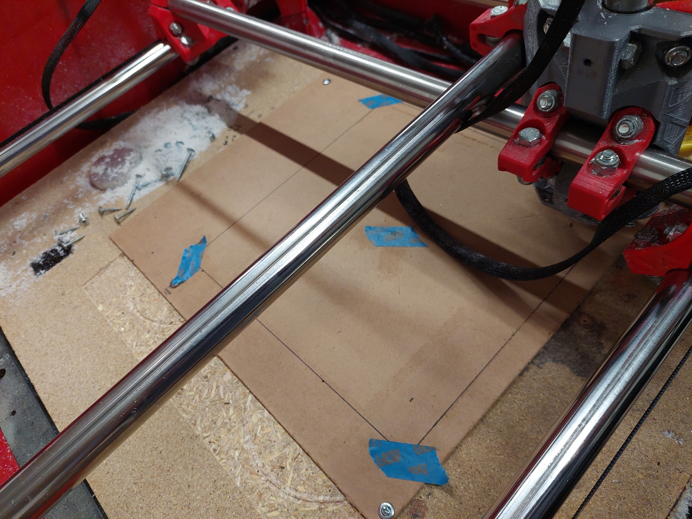
Step one is cut the largest square/circle you can, measure it to the best of your ability. We need each axis, at least, and both diagonals. Then do it again and see what numbers you get a second time…and more if you really want to get into repeatability.

From there we will see if you are even close dimensionally, and then we can discuss how square you are. Square is extremely easy to adjust with M666, much more so than screws, but we need more than one number to reference. I know the holes seemed to work better for you but we can not help you with that, we have to have numbers.

The larger problem usually by far is always dimensional accuracy. You have belts, pulleys, bearings, routers, collets, part flex, rail flex, and endmills that all add inaccuracies.

I am absolutely in for seeing how far you can dial in a giant 15"x15" bed, and I will help in anyway I can.

Lets see some numbers. I am not really sure how to start to help without lots of nerdy numbers for me to use.

This only tells me how far you are off, not where and by how much. I have no frame of reference to tell you what is wrong or where, or even if that is + or -.

Are you sure the bearing and bolts aren’t causing some measurement error?

When milling, are you using a finishing pass? If you care about accuracy while milling, dialing in your finishing pass settings is key.

Your diagrams and text make it seem like there is a difference between adjusting X and Y when talking about square. I will tell you, it doesn’t matter. If X abd Y are perpendicular, then you will get square movements. It is about adjusting the angle between X and Y not the individual axis.

When you are close, using M666 to adjust the offset is preferable because it is repeatable. If you go the wrong way, you can go back to exactly where you were.

The other two forms of error are: scale and backlash. They are independent on each axis, but they should be about the same, since the axis are built the same.

If you move from 0 to 150mm and it moves 149mm, you may have 1mm of backlash, or be off by 1/150 in scale. Be careful when adjusting scale. You need to consider backlash. There is backlash compensation in SW, but the best way to fix it is physically. First, by getting everything tight (but not overtightened) and then by using finishing passes to reduce the load on the precision pass. Scale can be adjusted by adjusting steps/mm. But most often, you are only compensating for belt stretch. Everything else (motors, microstepping, number of teeth on the pulleys) is perfectly fixed (there aren’t 15.99 teeth on the pulley).

The circle test is what I would call (in software engineering) a “systems test”. You are testing end to end. Including the scale, squareness, router errors, loaded flex, and scale/backlash. It also includes the bearing and center bolt.

Instead, what Ryan is suggesting are tests that are subsystem or unit tests. Make measurements with less of the system involved. Ideally, isolate the one thing you can adjust and make an adjustment. Then go to the system test.

4 Likes

VERY GOOD INPUT. Thank you so much. That gives me a lot to think about. I forgot about the fact I may be adding error with a cut part vs. a no load scale drawing. I know runout is not an issue, but other things could be like backlash or belt tension and I need to to correlate the cut part error to the drawing error before measuring cut circles… I kind assumed I was good because I was getting similar results, but I need to verify that first. I do use finishing passes on measures surface.

Believe it or not I am formally trained in measurement system analysis. But like any dummy I was trying to jump to the finish line and cut the next parts instead of working this through systematically.

Jeffe, this is what I was trying to get my head around…

“Your diagrams and text make it seem like there is a difference between adjusting X and Y when talking about square. I will tell you, it doesn’t matter. If X abd Y are perpendicular, then you will get square movements. It is about adjusting the angle between X and Y not the individual axis.”

So in reality, in my testing so far, I may have just been making gross adjustments and chasing my tail. I hope not, but that is OK too.

More to come, with data! You guys have me thinking in the right direction now. Again, if I can develop a better way of getting there I will write it up. I just thought of roughly 10 tests I can run to identify and measure the error better.

2 Likes

Jamie has made a pretty good pattern generator for some of this stuff:

https://vector76.github.io/gcode_tpgen/

It draws a little ruler going one way and then back the other, so you can see if the scale changes through the motion, and if backlash is an issue. If you look around the forums, you can see it used in a few places.

I believe it. I see a lot of very good engineers that have varying levels of ability in “detail oriented” or “creative problem solving”. There are some very good senior engineers that have one or the other attribute and not both. I consider myself to be more in the second camp, and drifting closer with each year of experience.

That is to just say, I appreciate the detail oriented types. Measurements and methodical testing are crucial to achieve the hardest (although often smallest) gains. The creative problem solving side is great at getting the 80% solution and then I constantly want to rewrite it all from scratch! We need both.

I have some ideas churning in my head now. Correct me if I am wrong, but if I manually move the gantry off zero to another location, it should be exactly the same as a program move? Even with M666 code?

I am more the creative type engineer also. But I am also very well trained in systematic problem solving. So I attack each problem based on what I think is the best approach. Quick changes with failure/success or data driven small steps… But sometimes I chose the wrong path and need to change directions, like now.

If you home it, it (the truck) stops at what it considers zero, from there if you move it, it should go the distance you expect. This distance should not need any calibration, all the parts are fixed and not variable.

M666 just moves one side precisely to account for your human hands mounting the endstops in a different place on each rail. X1 is the reference, X2 moves due to M666 to account for mounting location differences.

The part you need to test is a cut part to factor in the Z axis, the tool, collet, endmill, and cutting load. Moving the axis alone and testing should not be a measurable offset. Technically, all OD’s should be a bit undersized and all ID’s should be a bit oversized due to runout alone.

As long as by “manually move” you mean “use the machine controls to change the tool’s position.” If you use your hands to move the machine around, it won’t have any idea where it is any longer.

Ok, a lot to cover tonight.

  1. Lineraity- I manually moved both Xand Y axis over a 600mm scale I purchased from a discount tool store. At first I thought I was off my almost a full mm at length. So then I went and checked the scale against a tape rule ro verify it. I found with a little bending it created some error. So I think I am OK here. I was pushing down a little hard… I also checked it against another 12" precision scale I had and it was dead on.

  2. Repeatability- I drilled my 300 x 300 box five times with no discernable difference in any dimension. This has been my experience in the past.

  3. Repeatability after load - I ran 24" of slot in the pvc sheet I have from 2 directions and drilled a hole at the end. Both holes lined up perfectly.

  4. Machine deflection. I put a dial indicator on the spindle and pushed the core around some. I was surprised at what I found. It requires very little force to deflect the spindle in any direction. It starts moving immediately and is very spring like in response. There was 0.0035" movement in both x and y directions that did not recover. It appears this movement is allowed by the belts. I am really curious now what the cut dimensions are compared to the unloaded movement. Heavier loading = more error.

  5. M665 settings have no effect on my machine. For example I set a M666 X1.5, then M666 to verify the setting. Then run my 300x300 box with no change. I tried this with both X and Y offsets and with both X1 and Y1 endstops leading and trailing X2/Y2.

  6. Resolution- I verified with my 600mm scale I could distinguish down to 0.25mm.

  7. Squaring of rails - once again I got everything square by adjusting end stops. At least within .5mm maybe less. By running 20 or more boxes to dial this in I have a better feel now for fine vs. Gross adjustments and how they affect the box diagonals. I did not cut any more circles yet.