Help with endstops, of how low can you go?

1- This means your steps per mm are correct as expected.
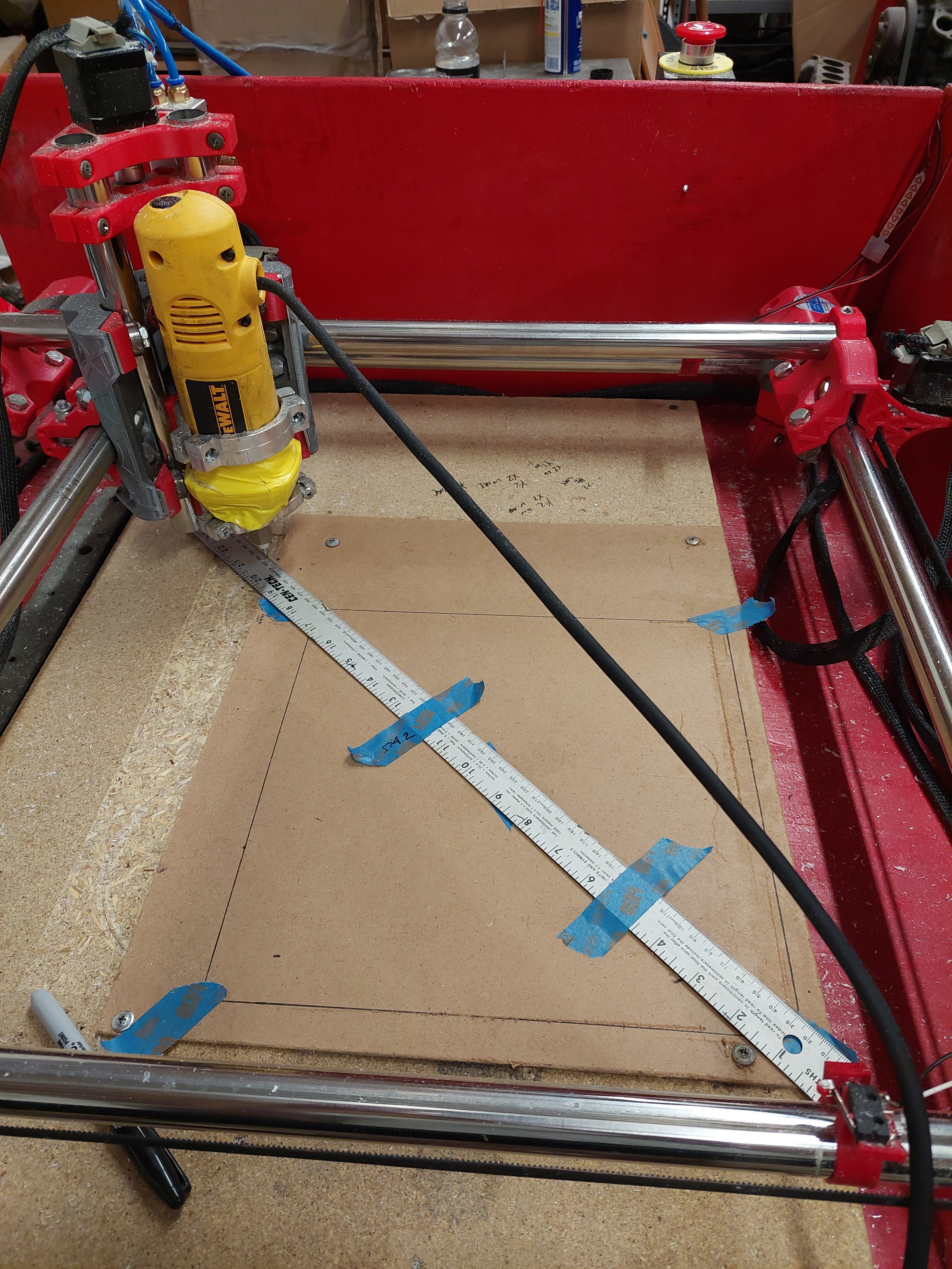
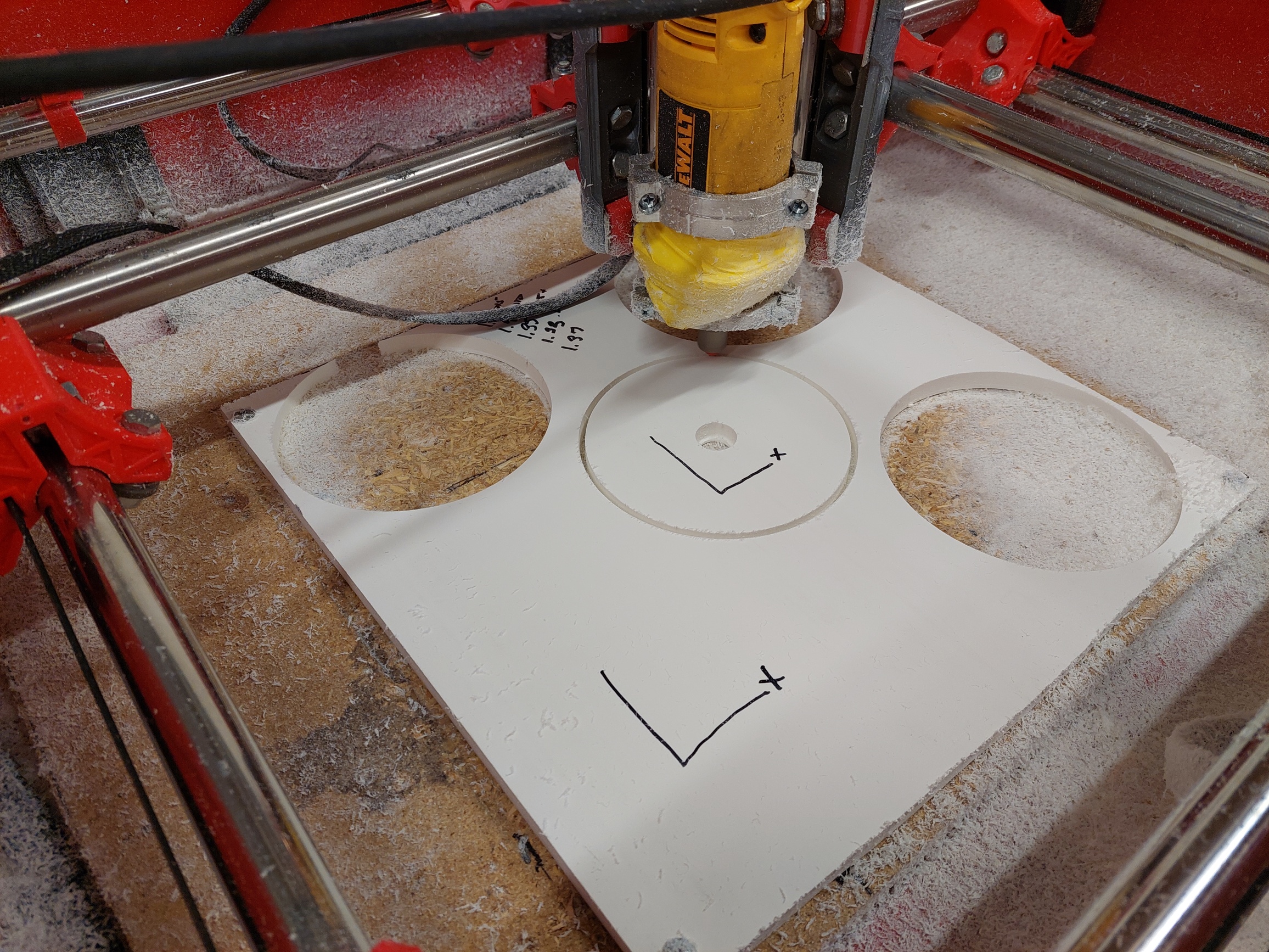
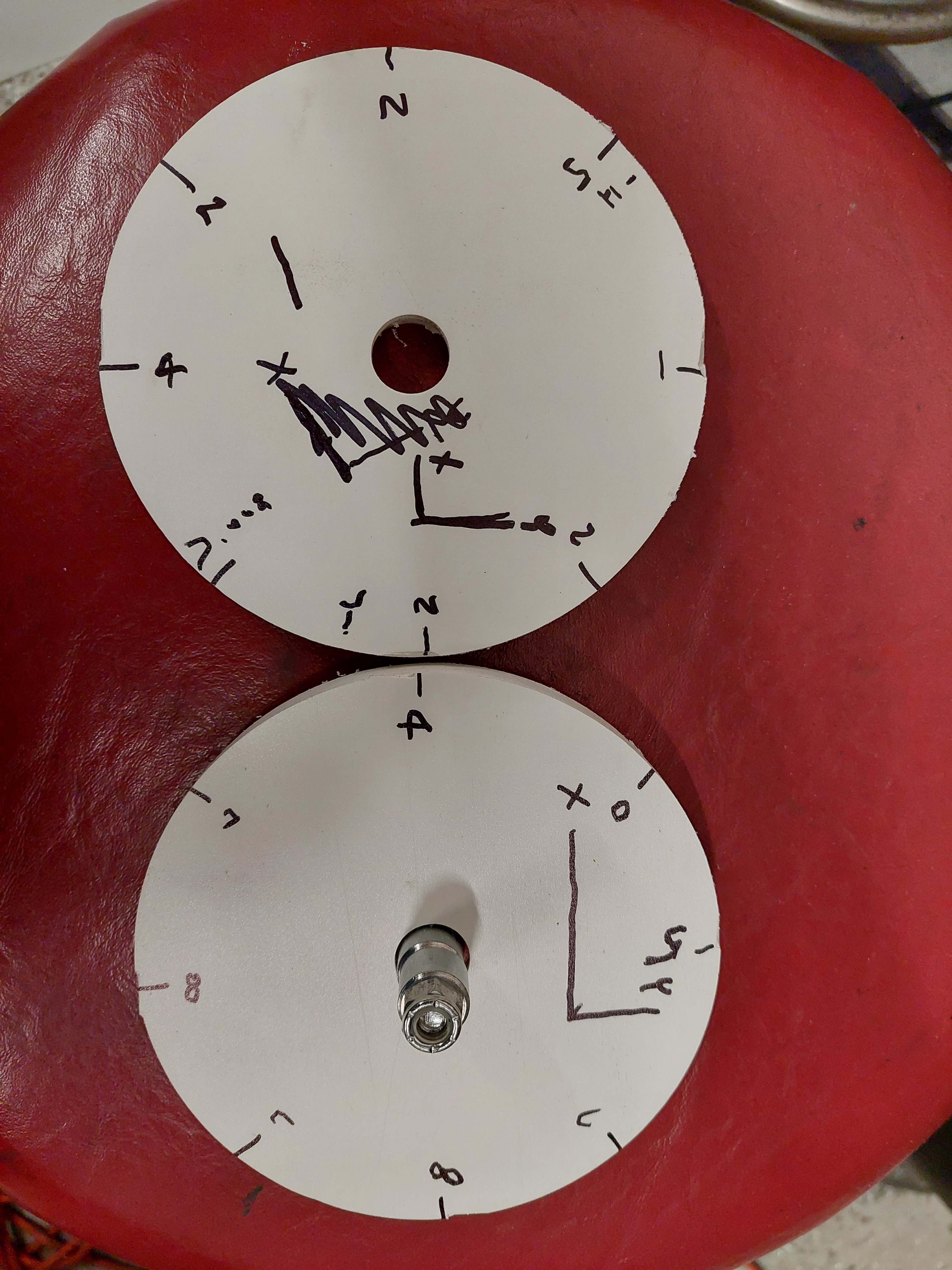
2-Drilling a hole does not load any axis other than Z, see #1. You move to each location under no load. You did not measure hole diameter, so you can not check run out. You also did not measure depth so we can’t check Z deflection.
3-See #1 you moved it under load, then released the load and drilled holes. You will not skips steps unless you are doing something drastically wrong. Without skipping steps you will see no deviation drilling holes. Any load is basically a spring, it will return.
4- You can push the machine extremely hard. This means nothing. When you cut material, it has very little actual load and is from the tip of the machine. If you want to do a load test I have several threads on here and it can be done quick and dirty from a luggage scale and a dial indicator, from the tip of the cutter. This is not a real cut and pushing doesn’t simulate a real load, carbide is sharp, and a good cut is under 1.9kg load on aluminum (for the testing we have done).
5-When you change M666 you need to re home. You can test the resting position after homing. This works and is proven to work, so if you are not sure how to test it try with larger offsets 2+mm, you can see this with the naked eye.
6-Not sure what this was.
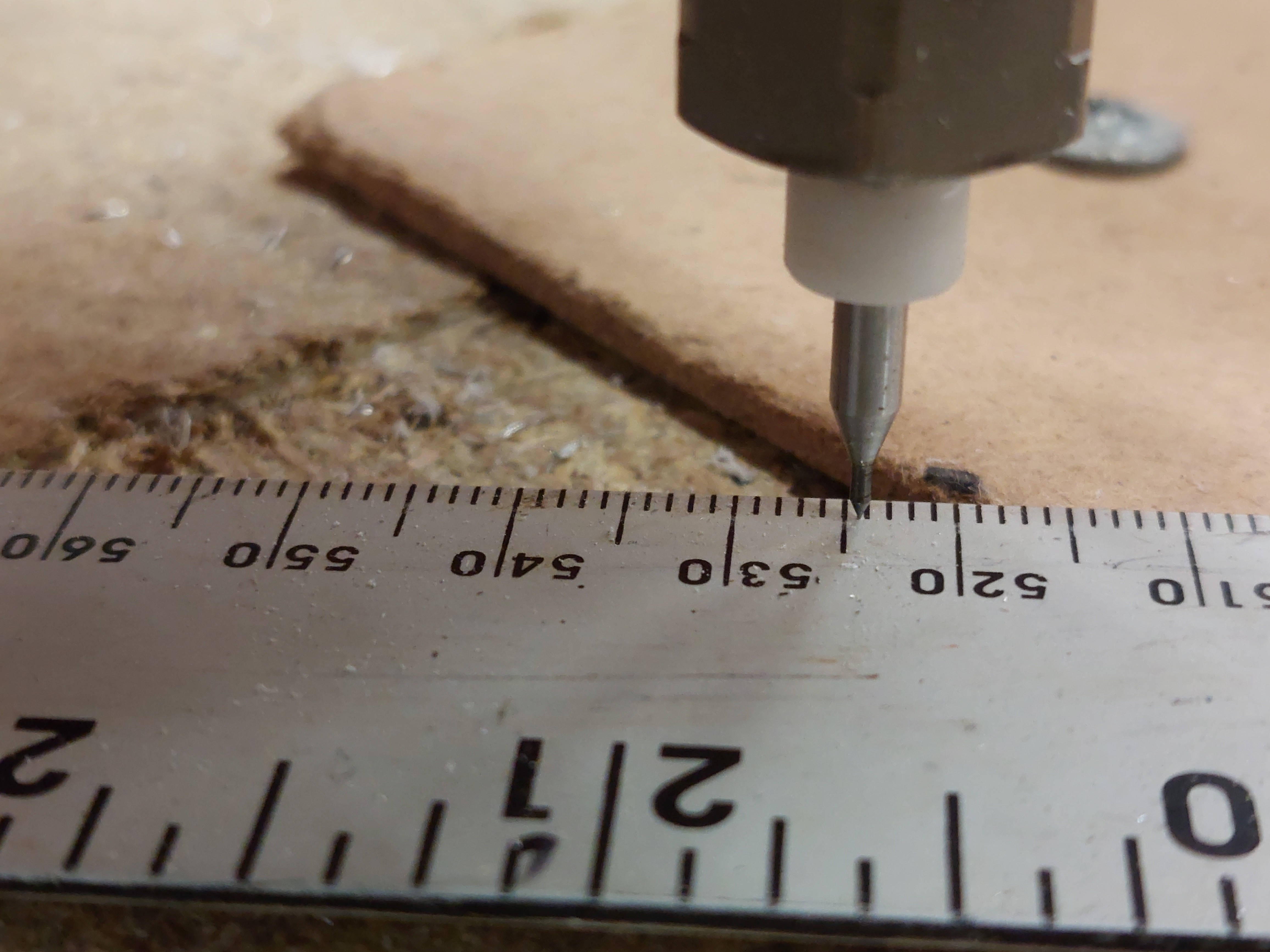
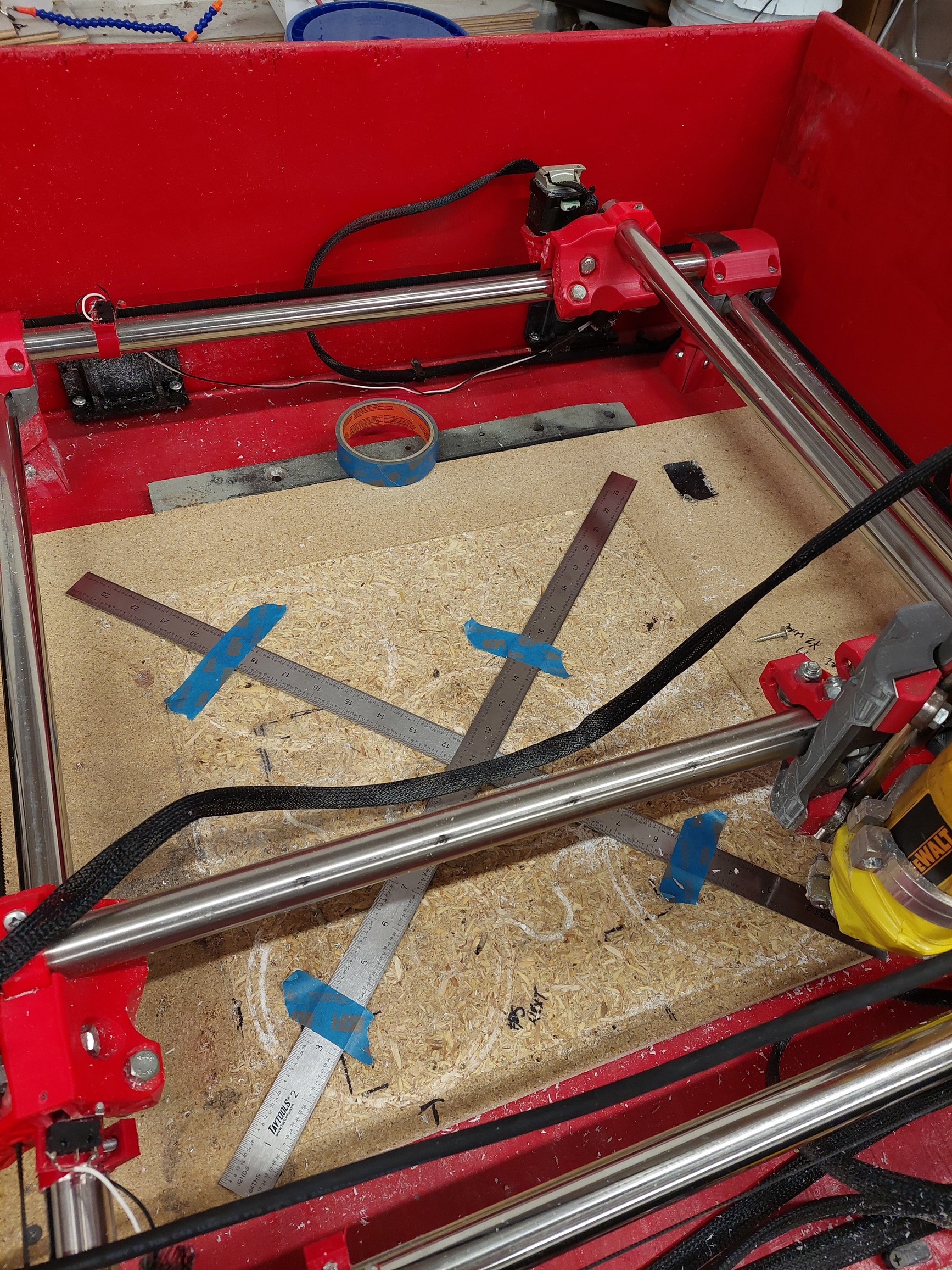
7-Meaning outer dimensions, or endstop block positions, either way, the more accurate the better, but M666 will usually be the finalizing step, to get the last 0.2mm or so square. I know no other way to test this that drawing or cutting.

You tested the machine and verified it is accurate. Not drawing or cutting parts you can take measurements and verufy how square it is. I can;t think of a way to do this without drawing and eventually cutting.

When you cut something, you are testing the machine as a whole system. Nothing is perfect, and if you dialed everything in to the 0.001mm like I said before you should have smaller outer dimensions than expected, and larger inner do to all sorts of systematic error stack up (belts bearings, bolts, plastic, temperature) but mainly from runout (all spindles have it). If your cuts came out 0.1 OD small and 0.1mm ID large, you would have very extremely well set machine, from there we could tune it to get more expected results in CAM very easily (I.E. leave 0.1mm on the stock). We can not tune it without real world numbers though.

Is number 6 the 600mm holes in the blue tape? The diagonals are matching within 0.25mm?

If so that is excellent :partying_face:. That just means it is time to make real cuts, your machine is as accurate as you can measure now we can tweak your actual cuts to perfect them to your needs.

I am definitely within .5mm square now. Close to .25mm. I am sure I can get even closer… I wear magnification glasses when reading. The resolution I mentioned in #6 is how well I can take measurements. I can distinguish a .2mm change in measurement with my method. The no-load repeatability must be way less than that. By drilling the tiny holes my measurements take runout into account.

I will try the M666 gcode again, I can’t believe I didn’t home after in the input in the 20+ times I tried it, but it is possible.

I checked spindle/collet runout with dial indicator previously. It is within 0.0015". I just ordered a higher resolution metric gauge so I can measure more precise.

I did realize the cut part inner and outer diameters were slightly off. I have measured that in the past. The fact my circles are really elipses made that a minor point… I will go back to that when I can cut closer to a perfect circle.

The machine deflection was much more than I expected. I have a calibrated force gauge. I put it on the spindle and had 0.005" movement with about 0.9kg. And as I mentioned 0.0035 did not “spring back” and appeared to be in the belts… It looks so rigid when cutting but it is really just a big spring. But the good thing is the deflection seemed equal in all directions so again I expect consistent and repeatable cuts. This was my last test last night so I will explore this more in the future when I am satisfied with no load alignment. Good to walk away and think about things.
.

Over a square of 600mm, that is easily under a tenth of a degree off. I am seeing 0.067 degrees but that might even be double. Haven’t had enough coffee to think straight yet. That is amazing for the things I do but I am not sure what you are going for.

M666 really tells the machine to move after finding an endstop (which are theoretically capable of +/-0.01mm). So when you home an axis it find the endstop and can move either + or minus that value you tell it. So you can actually see it move. It homes fast, backs off homes slow for more precision, then moves your specified M666 on only one side. So if you want to test it you can put a dial indicator in teh same position of your end stop block and watch the values.

Numbers I can geek out on! So we are getting some real numbers now. Your spindle is getting you +0.0381mm (at the collet, that is an angle though, so longer bits will swing a wider cone at the bottom). So in a perfect world your OD should be at least double that smaller, and ID should be double that larger. Then you have a endstop capable of, ±0.01mm.
Now where this gets funky is after you factor that in, all motion systems have tiny bit of slop (belts being some of the least sloppy believe it or not), so now that machine will not actually move as far as you ask it to on top of that.

So now you have a real numbers, once you get repeatable cuts, with repeatable dimensions you can use your CAM to account for all this. You can also make your CAD account for this as well. Once you know what your machine is capable of you can make dims 0.2mm bigger or smaller to account for all of this. I made a few injection molds in my past job and I had to go to the machine shop and sit down with the machinist and work through all critical dimensions in CAD with them to account for this sort of stuff, and select the machine we would use to make the molds. Depending on the resolution required.

Where did you apply the force and where did you measure the deflection? 0.127mm with nearly a kilo of force, am I extremely proud of that number as the designer, but I do feel that is way too low.

To put that in perspective that is what the machine would see cutting PVC with an 1/8" endmill 6mm deep at 1,600mm/s…we typically cut around 15-20mm/s.

Correct, all machines will have slop.

Every machine in the world is this way, sky scrapers sway in the wind.

So just to put all of this in perspective, you built a relatively large CNC (15"x15" = 225sq/in) out of plastic for $500ish dollars and you are trying to dial in 0.1mm accuracy and precision, I think we can get pretty close. The tormach 440 is 6.5"x10" = 65sq/in and starts at $6.5k and ends up a few K higher. I am seeing people say thay are getting within 0.07mm with a bit of dialing in. But now remember that is nearly 3.5 times less XY area, and 13 times more expensive at the least.
The largest tormach has an XY area of 198sq/in and starts at $21k.
The hand waving part of all of this is they have significantly larger Z axis though.

All of that to say, if you are not happy with the accuracy you are getting when you have reach the limits of your measuring capabilities when dialing this in…make the machine smaller.

I just had a look and protolabs default tolerances are 0.13mm, not seeing any options for higher, but that gives a good number to design around.

1 Like

No complaints here! I just calculated a force of 2.5N or roughly. 0.25kg when cutting aluminum with my settings and double that for steel. As I have suspected all along, machine stiffness is a non issue (for me). That is why I was contemplating some stiffness measurements so people (or me) could troubleshoot with. In my experience, whenever I thought my machine was not stiff enough, I found another issue causing the problem.

I measured the deflection on the collet nut with dial indicator and pulled with a hook just above the nut on the router round shaft. Z axis was down fairly low and I know this is another variable. I was surprised by the amount of movement because I often grab the core or router and pull it in different directions and it feels rock solid. My guess is even though the movement starts with a touch of a finger, the overall spring rate must be quite high. I am sure of that.

My <.5mm error is over a 300mm square. My bed is only 400sq. But I am positive I can get it to <.25mm. Then I will start cutting again. I slightly misspoke earlier. For the project I am working on, the cut error probably needs to be roughly 0.25-0.50mm on a 200mm circle. Where I am looking for more better is actually under no load condition I just need to center mark a bolt circle which I will drill out later on a drill press. This thread is giving much more confidence I can hit that.

Sorry I mis-stated this also. My 0.0015 runout is really 0.0005" measured with a 0.125" pin inserted into the collet probably 5mm down the shank. I may play around with that some more to look for a cone angle when I get my new gauge. That is the reason I ordered a new gauge because it is hard to read .0005 on a .001 dial indicator. It is a very critical dimension and should probably be rechecked before I start any big project.
.

2 Likes

Glad your happy I just always need to put a comparison summary in for future people that read this thread. So many people dismiss and call this CNC a toy. I always feel the need to put things into perspective when we get this far into accuracy and precision. Some might take these numbers in the wrong way.

I am not convinced you need any fancy indicators to check run out. There is nothing you can do other that get a different spindle or collet. I am always far more concerned with hitting the same numbers on a real part multiple times. Once you have precision, you can adjust for accuracy very easily. Even if you had a ton of run out or super sloppy belts, just account for it, and you are fine. You have a square and you have the steps verified, lets check precision!!!

Happy? I am your biggest fan! I will try to be careful to keep perspective in my posts.MPCNC has passed my expectations 10X. I keep trying to find the limits because that allows even more projects to be planned. I was just happy you did not tell me higher accuracy could not be done! Your assistance to guide me through it is much appreciated… The only limit I have found to date is speed. But how much can you expect with 3mm tools? I don’t think anyone would try to hog out a 40lb aluminum forging with this… I just need to find room for that low rider I am dreaming about to cut sheetmetal…

Overall I am thinking big picture here. I have already incorporated MPCNC Into my tool box.If I can take this to the next level, I might as well bring some others with me with simple easy to follow instructions. In reality it is for selfish reasons. Through this entire squaring exercise I am only thinking about hitting a mark, and then being able to perform another set up in 5 minutes or less if I happen to bump things around or disassemble. Trust me, I would give up on this machine if I found something “finicky” or unreliable. I am doing some things you would not recommend, but it keeps on spitting out parts. I will post more of that stuff later. I spend a lot more time troubleshooting and replacing stuff on my 3D printer than I do with MPCNC.

And as I have mentioned before in other posts, if you buy some parts and follow the directions you have a machine that can do stuff. Designing parts and generating gcodes to get what you want out of it is much more difficult IMHO. You will not see me posting my designs up anywhere.

3 Likes

I am ready to see what I can do with 1/4" in metals now. After doing the speeds runs in MDF I was a bit shocked at what the machine can handle. I do think the small bits add too much flex when metals come in to play.

:+1:

2 Likes

Someday I hope to get there also but it will come with a router upgrade. Not ready yet. I went to 3/8 or1/2 long flutes for aluminum and 1/4" for steel to solve my issues with 1/8" end mill flex. The Mister helps too.

Great discussion! I believe 0.1mm accuracy should be possible if not quite easy.

One trick that worked for my 300x600mm work area was to lay a 1m long shiny metal ruler along an axis, firmly fix a fine needle to the spindle mount, and use the reflection of the needle to ensure a one-eyed reading was perpendicular. Here is a photo.

With that, I could easily measure travel to 0.1mm across the whole bed. I used that to tweak my steps per mm, before doing the squaring.

5 Likes

Oh I think I need to try that!

I did that last night. Here are some photos. I can read down to 0.2mm with my “glasses”, Seems to work very well and I ordered some additional 24" scales on Amazon to see marks better. BUT after squaring it all up I cut another circle and it was all funky. I am still investigating and will post results soon.


2 Likes

I discovered at least one of my problems after 4 hours of trying to square it down to 0.2mm. I could get within 1mm on the diagonals then I would make 1 more minor change and get a random answer on the diagonals either better or worse. Adding more confusion it would usually repeat. A couple times I got it down to 0.5mm. Then I cut another circle with it 1.5mm out of round. After pulling my hair out for hours I believe my limit switches are not repeating. It is the only thing it could be after I finally observed it change a couple of times on the repeat.
The limit switches are some I had in storage of unknown origin. I found the utilimaker switches that came with the endstop kit then designed and printed some better clamps for mounting.

Hope to try it all out again tomorrow… More updates coming.

Those endstops should fit on the trucks with the dual wiring kit. Any reason to reverse it?

You can also slow down the homing after the bump to get better accuracy.

That sounds interesting. How? In the firmware?

Not sure what you mean by reversing it.

Ok a lot to unpack today. Spent many hours playing with squaring up. The good news is I swapped out my limit switches and the measurements started looking like I expected. I used my new 24" scales ordered of Amazon and quickly squared it up to maybe 0.75mm or so. Each M665 movement gave me what I was expecting for a change. Then I swapped to cutting circles again. The first looked ok but was flat on the bottom and about 1mm out of round. So I started thinking about what could cause that. My trucks are rather tight and my first thought was with the twist imposed by the squaring, they are even more bound…my machine is quite a bit of unsquare in idle position. So I started loosening up the trucks and core bearings until they were just barely touching the rails. And I reset all the bearing tension with motors engaged and M666 offset in. Every change I made gave a better result. So then I began adjusting offset again based on my cut circle results. I started with .020" out of round and ended AT 0.005" OUT OF ROUND!. With a 1.35mm offset in Y axis. So what next? I kept adjusting the offset just to see how low I could go. And things started getting worse. Sometimes the flat spot would come back sort of randomly. So I kept playing with bearing tension but still kept getting the random flat spot, usually near the bottom. So I gave up and went back to my 1.35mm offset but could not duplicate the 0.005" out of round. I ended up at 0.008" out of round, which I know is not bad, but I fear it will not always repeat and may jump back to 1/2 mm.

Anyway here are some pics. First is my dual scale setup.

Then my new limit switch clamps with covers to keep out debris.

A shot of the circle cuts.

And my 0.005 circle next to my 0.008 circle.

And an example of how things can jump out drastically with.a flat spot. You can see the out of roundness I you look closely. All the numbers are thousands of inch.

Flat spot = loose grub screw?

How thick of a full depth finishing pass are you running? Climb or conventional?

In configuration.adv search “bump”.

By design the endstops were mounted on the trucks not the rails, any particular reason why you swapped it? On the trucks the endstop are upside down and shielded by the core, meaning they have an extremely low chance of catching debris.

1 Like