I would like to use my Bosh Trim Router (GKF125CE) for a new LowRider V3 Build, instead of buying a new one. I can find the DW611 and Makita 700 CAD mounts, but the generic Blank Tool does not look at all like these 2. My problem is that the Bosh motor diameter is 72mm, much bigger than the DW. So my question is, what I need to do to customize one of these adapters, or does anybody can guide me on how to use the Blank Tool Mount in Fusion to create one for this Bosh trim router.
Any help will be greatly appreciated. Thanks!
I don’t have an LR3, but I was curious about the LR3 tool mounts, so I took a look at the models.
Bosh motor diameter is 72mm, much bigger than the DW
The Dewalt mount is for the DWP611, not the smaller DW660. The DWP611 is 70mm in diameter, so only 2mm smaller than what you need.
the generic Blank Tool does not look at all like these 2
The blank shows you the volume you have to work with along with the placement of the bolts in order to get a router to fit in the space provided in the LR3. One way of creating a mount is to carve the blank down, but that seems like a lot of work.
If I was doing this project id:
-
Create a rough model of the Bosh Trim Router. You need to capture the barrel diameter, the volume of the head, the placement of the locking button, and the placement of the cord. It doesn’t have to be pretty and can be done quickly using a block, a cylinder, fillets, and chamfers.
-
Move the blank, the DWP611 mount, and your Bosch model into the same Fusion document. You want to verify that the router fits in the volume and the DPW611 mount handles the lock button and the cord. I know for mounts for other MPCNCs, the cord connection needs to be modified.
-
Assuming everything checks out in the previous step, modify the DWP611 mount to get your 72mm.
There are two issues with this approach. First, Ryan did not provide the STEP files for the Dewalt mount, and I don’t know if he plans on it in the future. You may have to convert and/or remodel the models. Second, the process is not as simple as just “boring” out the opening to 72mm.
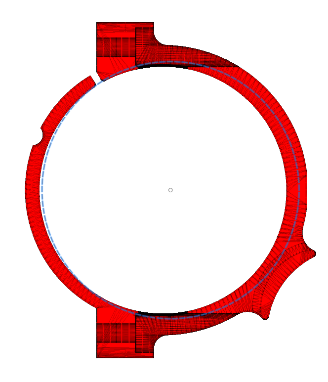
The dotted blue line is a 72mm circle placed on the Dewalt mount. The screw socket positions are fixed, so you half to consider how this is mounted, and taking the 72mm as I’ve placed the circle probably does not leave enough material.
1 Like
The dust collection is another part to consider. It has a few more constraints w.r.t. the router dimensions.
My second favorite hobby is remixing existing models as parametric ones in OpenSCAD. Tonight I will take a look at generalizing the existing two, unless Ryan beats me to it.
3 Likes
You’re all awesome!
When I looked at the Dewalt models, the dust collection seemed much simpler than the straps.
There is enough material so that a simple extrude of the circle would make the modification, and there is more bolt clearance. Just make sure the circle used for the mount straps is aligned with the circle used for the dust collection top piece.
Would a 1mm bushing work?woops got the sizes reversed
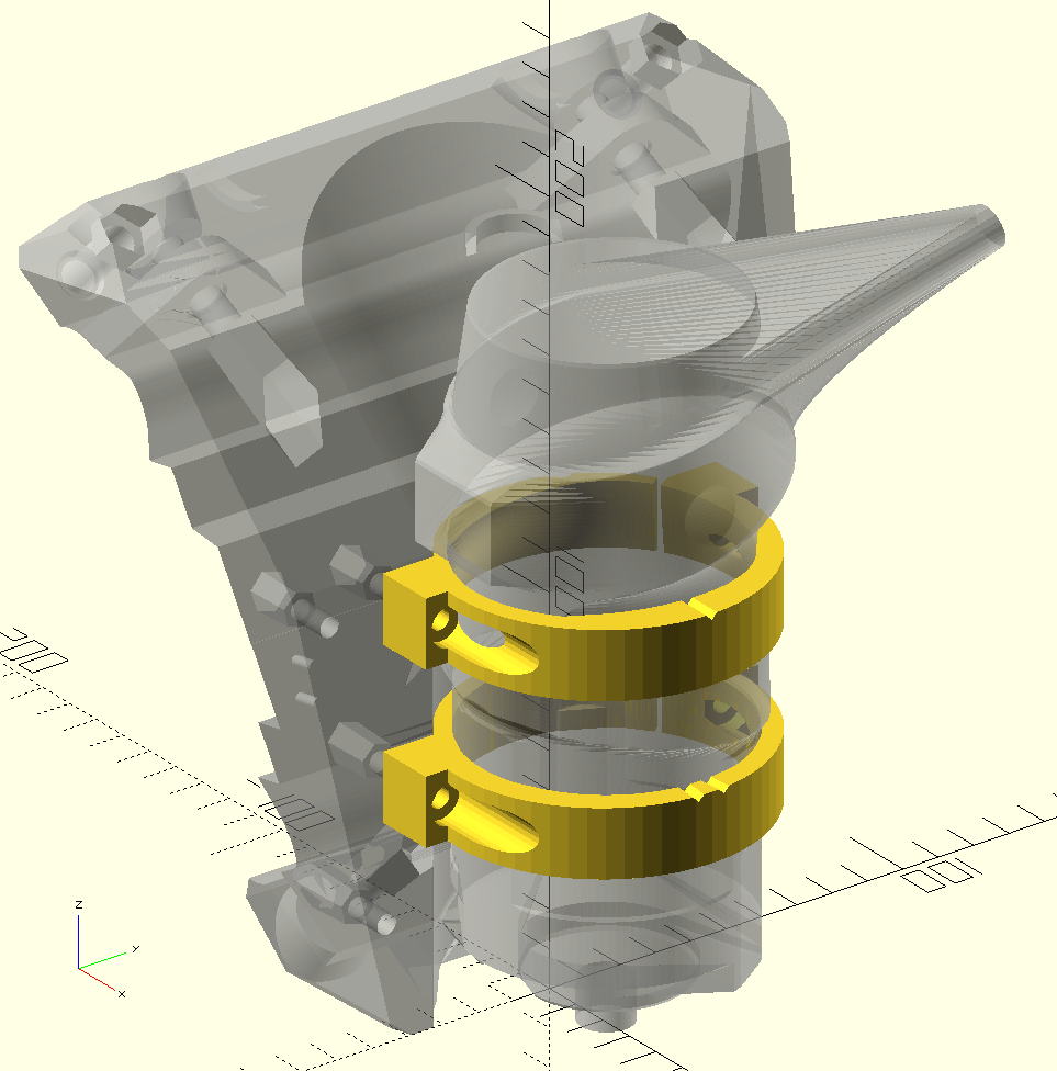
bosch72_tool_mount.zip (33.0 KB)
This is missing all the vacuum stuff and has just the straps, so this is incomplete, but perhaps it can at least get you going.
The 72mm size is getting to the point where the mounting bolts are almost too close together to fit the router between them. I’m not 100% sure you will be able to tighten the bolts once the router is in place.
If it is too tight, it would be possible to mount the router a bit farther away from the core. I can’t tell if it is too close and interfering.
1 Like
Thanks @jamiek and @robertbu. I attached a step file with blank, mount, and router so you can see what’s going on.
Bosh GFK125CE Mount v1.step.zip (900.6 KB)
1 Like
I have a Bosh as well, although very old, and i use a euro-mount on my LR2. Don´t know what size your model has close to the spindle, but my measure 43mm = standard euro-mount.
Here´s an example:
Theo
I have the Blank tool mount CAD, I guess I have not posted it yet? I need to have the link checked last time I shared it, it shared my entire fusion folder.
If the router is large there is another spare screw hole up and to the left, that might help. You can then fix it under the router as well. I have the dust part separate but you can just as easy keep it as one and use the lowest set of screw positions and the top extra one, shift the router slightly over away from the stepper a few mm to get a little more meat on the straps.
1 Like
Oh so cool, could you please just post it. Will be wonderful if you can post the mount and as well upper/lower vacuum parts.
Thanks!
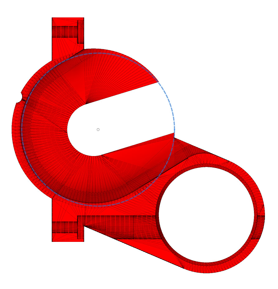
Cool router model. I did a quick search on GrabCAD before I first answered your question, and I did not find a model. Assuming the router model is accurate, you may be in a bit better position than I thought. Measuring the model, the barrel is 70mm, matching the diameter of the Dewalt. The contoured grip is the biggest issue. Maybe it can be removed? If you import the Dewalt mount and position the Bosh router, you get this:
I don’t know if the router rotation is correct. There are a number potential unknowns here and potential issues. My biggest issue is how to design the bottom and top mounts such that the router is guaranteed to remain vertical. Looking only at the models since I don’t have an LR3, and assuming the grip cannot be removed, my approach would to model the dust boot top and the lower mount as one unit (attached in back) and have the mount follow the grip at the top. This would have you a large holding area with four mounting screws. For the top mount, I’d design it as a half mount, perhaps with zip tie holes.
It appears you will have to modify the dust boot to accomidate the protrusions at the bottom of the router, and I don’t see the locking mechanism, but it will have to be accomidated.
Edit: If you want to punt on a dust boot, then you could simply create one long mount with four mounting screws. This would be the simplest solution to get up and running quickly. The only thing special would be accomidating the locking button.
1 Like
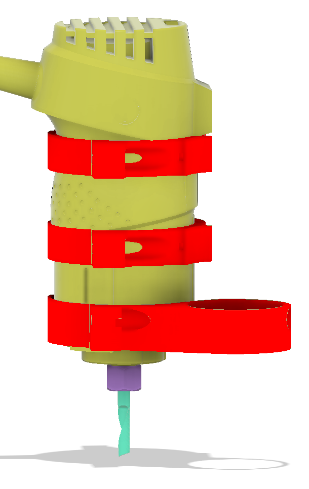
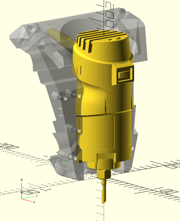
That router model is a big help. It will need to be rotated for the cord to clear the core, but it should be very doable. It won’t be a pure cylinder like the Dewalt or Makita, and I’m assuming it would be raised up so the collet nut is near the bottom of the core, like this. The dust boot should be doable.
I wonder if there can be a generic tool holder where you just subtract a model of your tool (angle grinder, DW660, or whatever) and you get something usable. Which I think is along the lines of what the blank is intending, but it’s not the same.
Okay, here we go. It is the Fusion 360 CAD for one of the two routers. It is not simple to adjust, but it should help.
I will post this to printable shortly as well.
1 Like
Well, I thought I had it out there…and It was.
https://www.printables.com/model/167687-lowrider-3-cnc-blank-tool-mount
1 Like
Sometimes OpenSCAD just refuses to operate with a model. I had problems even with benchy in the past, where ‘ordinary’ CSG operations like difference or intersection simply fail. It complains about a broken model, but no matter how much I “fix” the model, the problems persist, so my conclusion is that it has to be a bug deep down in CGAL that underpins OpenSCAD.
I was unable to subtract the tool from a blank strap to produce a fit to the complex shape.
I decided to try CadQuery, and the conceptual model of the stack is hard to get used to, but it does have the advantage that it can import and export STEP files directly.
Unfortunately CadQuery ALSO fails to take CSG differences of the router model. I also managed to crash it a couple of times, so I doubt I’ll be using it much.
I did manage to extract ‘slices’ of the tool, similar to projection(cut=true) within OpenSCAD (which didn’t work). So by exporting a bunch of 2D slices and stacking them up within OpenSCAD, and taking the convex hull in certain places, I managed to get an approximate model, which being the hull of slices should be pretty good for grabbing the tool without trying to grab all the nooks and crannies.
And finally, I am able to take a CSG difference!
Now that I got that working, the rest should be relatively straightforward.
In general I still think it’s reasonable to create generic mount where you simply subtract the tool to create a form-fitting mount, but it comes with a caveat: your model of the tool must be suitable for OpenSCAD perform a subtraction, and if it doesn’t, then God help you.
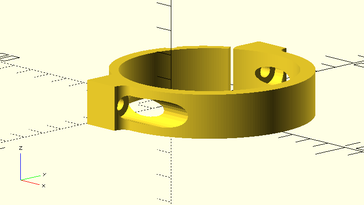
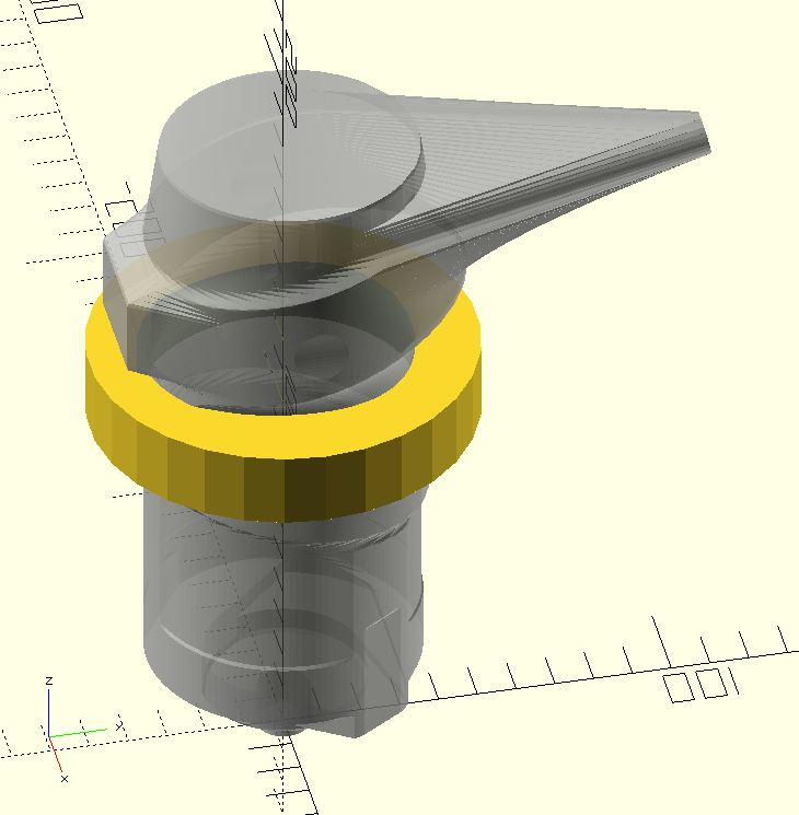
Okay, here we go:
https://www.printables.com/model/211581-lr3-generic-mount
This is lacking dust collection, which I will add later. I also added little marks on the straps so it’s obvious which is which, and which way is “up”.
I don’t have this tool, so I can’t say whether this works or not for real, but it’s my best attempt based on the model file.
I’m hoping the same general approach can work with minimal changes for RotoZip or DW660 or a 500W DC spindle or angle grinder or whatever else. A chainsaw will need a different style of mount, so that will not be covered by this design.
1 Like
AWesome!
It looks like I won’t be doing a dust boot for the Bosch router, mainly because I don’t have one and there is a high chance that I will make a mistake that makes it really bad. There appear to be vents on the bottom that I assume are exhaust vents, and keeping those clear enough is trial and error that I’m not set up to do. Plus other clearances such as the button or whatever to lock the spindle for changing the bit, I can’t really make sure that still works with the dust boot in place.
Sorry, but I’m going to have to call it done as it is now.
2 Likes