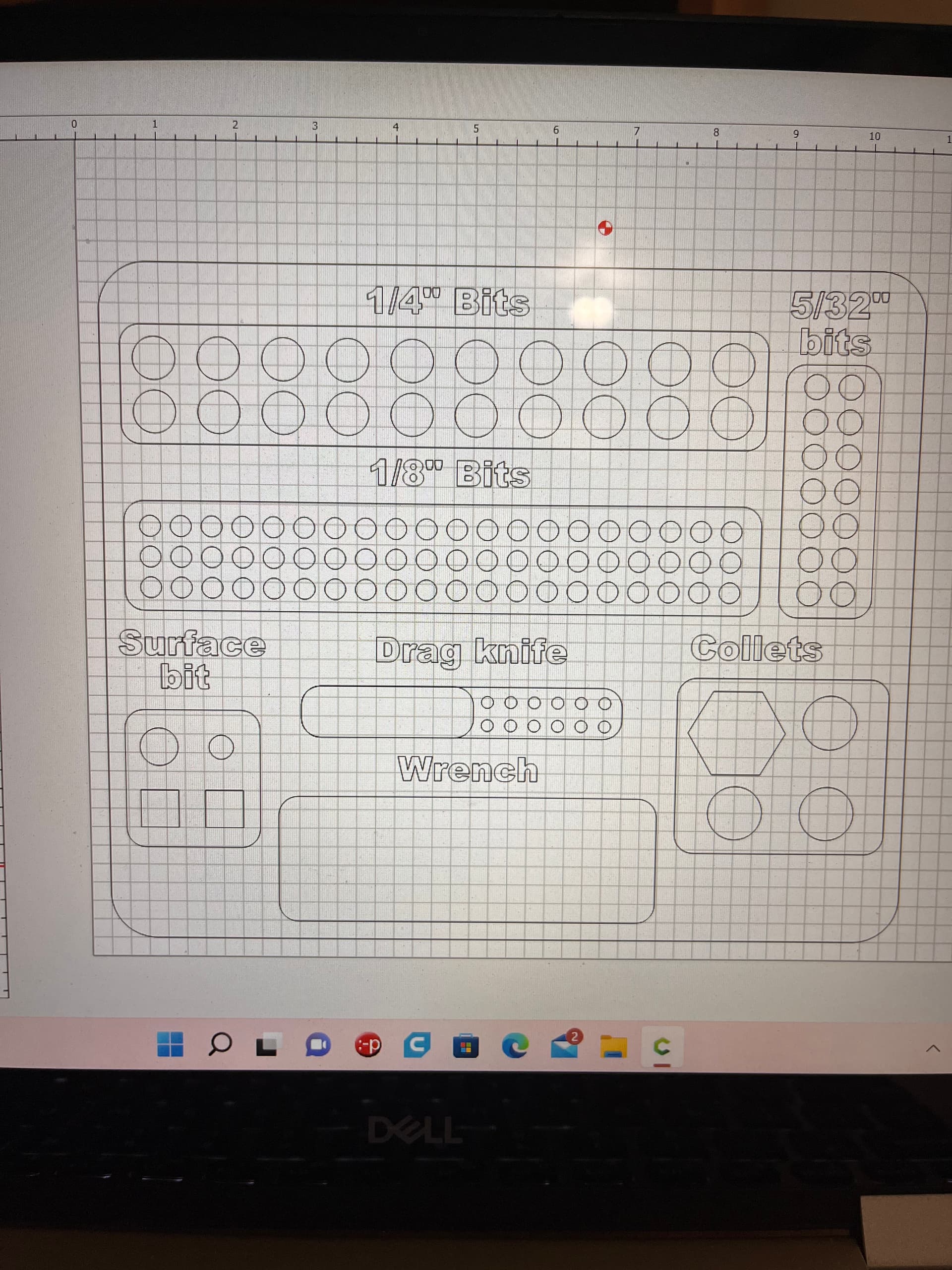
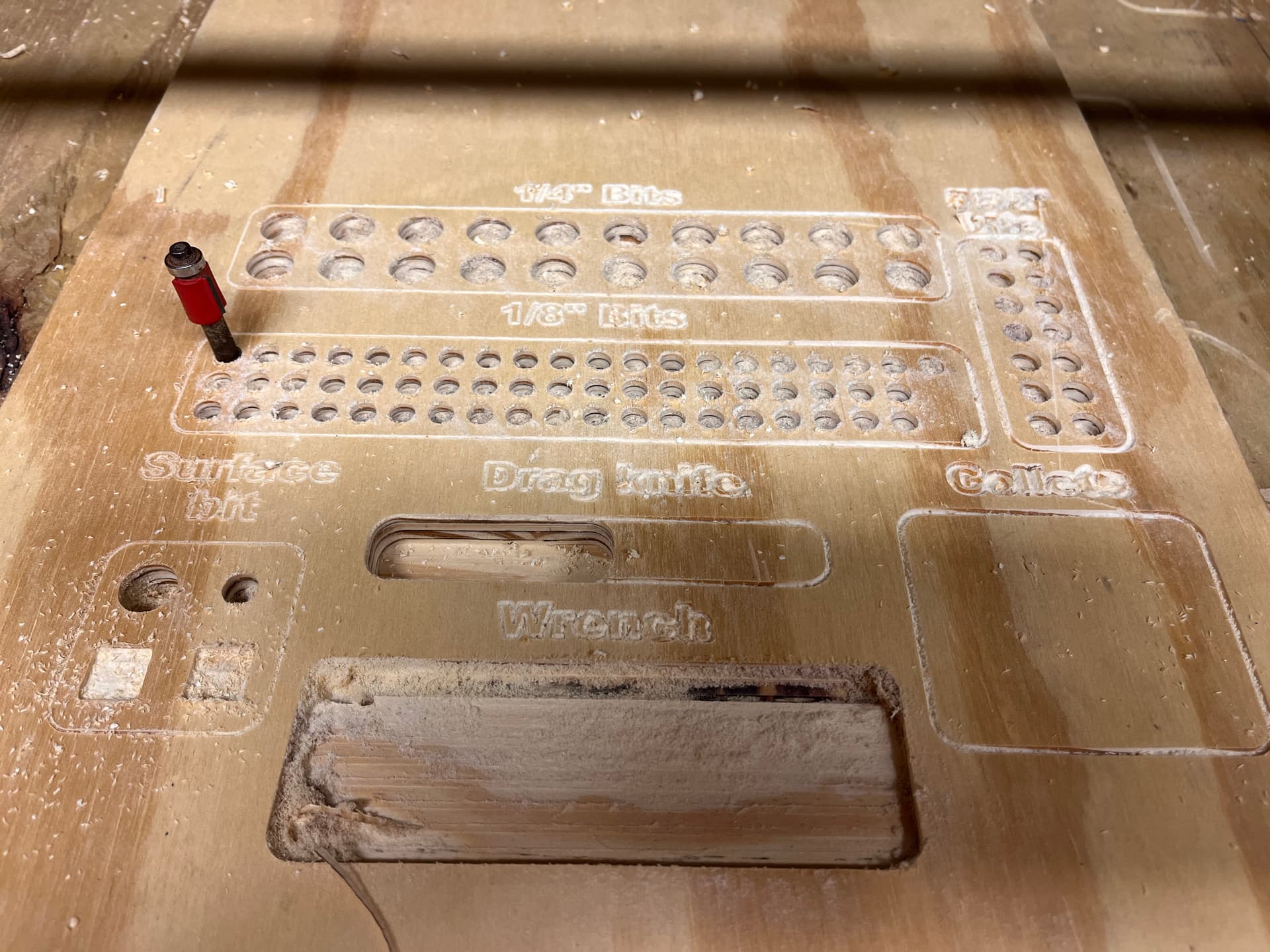
Can anyone explain to me how these holes got so far off in size I have a feeling it has something to do with the transfer from carbide create to estlecam but I’m not sure?Processing: image.jpg…
1 Like
The answer is when you imported it you picked the wrong units.
To figure that part out though takes a bit of work. Either you check the settings in carbide create, or you need to know how big something is supposed to be exactly, and then how big it actually measures. Like the large rectangle width.
For example, if it was 25.4x too big it was exported in mm, and you imported it in inches.
In the milling basics or the estlcam basics page I show a way to set the grid so you can verify things before you spend the time cutting them.
I thought that as well but I went back and checked my measurements and they where still reading in millimeters as being correct. But I’m gonna do a little more investigation as soon as I can. I looked last night and the grid was set up at 10mm by 10mm so I set it up to 23.4mm by 23.4mm or what ever it was that comes out to 1in and made the circles again and they still look big.
So at that point measure your machine’s actual movements. Manually move it 12", is it actually 12".
Sorry for jumping straight to software, I assumed you had already checked that part on setup.
When I made the charcuterie boards they measured just as I designed, that’s the first time I have designed anything with alot of hole that needed to be a certain size. Even the pockets measured out right. It’s only the holes that didn’t size right.
But I did use Onshape cad to draw the sketch. So I will look into the post processing on carbide create and see what it says.
Ohhhhh, I bet you cut outside the line instead of inside the line!!! You could even try helical drill for those holes.
1 Like
I pressed the hole button in carbide so it should have done the inside.
You did the design in Carbide create and the CAM in Estlcam?
In estlcam a hole is just a path, and you can select either side of the path or centered on it.
I’m sorry I take that back I pressed the hole function in estlecam.
It that is the case, and the outer shapes are correct, the tool selected in estlcam when you pressed the drill function must have been the wrong diameter.
I use the drill function on most every job and have never had an issue with it.
Unless I change bit size for every hole the drill function wouldn’t work as far as I know, I used it once and it just drilled straight down and made the hole severely under sized.
Give me your .e10 file so I can check. Go to estlcam and save the project file. Adding the gcode as well would let us take a look.
I have given you a lot of options and you have said all of them are correct. One of them really has to not be correct. I really can not think of any reason every dimension is perfect except all of your holes.
1 Like
 I feel so stupid I figured out my problem. When making a circle in carbide it ask for the radius not diameter so when I put .25 as my desired hole size it was making my hole .5” diameter.
2 Likes
I just made that same mistake on a calculation. Don’t feel bad, it happens. I am just glad it wasn’t something harder to fix.
P.S. Radius is a very weird thing to ask for on a hole…it is not a round over.
Lol me too. Such a simple mistake I wish they would just ask for diameter, that would be so much simpler.
From a coder’s point of view, it makes sense. Diameter doesn’t make sense for an arc, and a circle is just a specific case of an arc. Freecad defaults to radius, too.
Just one more of the cases where computers make good tools for people, and that intersection where the people writing the programs have to learn to think more like the people who use the programs. (In relative terms, engineers are easy, I get to work with accountants…)
3 Likes
Well that makes sense, thanks.
1 Like