My grid uses 3.5" wide 1/2 birch plywood strips. I have 1/2 MDF on the bottom and 3/4 MDF on top.
1 Like
Endstops are not needed. You need to tell the machine where to start. But in CNC, it is based on the workpiece, not the endstops. So you will set up a job by moving the bit to the starting location and reset the coordinates to zero.
Where endstops are handy are two cases:
- These machine use two motors that move in lock step. You need to start them out square and then they will stay square. If you want a shortcut, putting an endstop to each motor to reach (dual endstops), will let the machine square itself. It is a bit more complicated than that. But that is the idea.
- If you are making 16 coasters or something, you will probably make a jig to hold the stock, and then just pop in new blanks. You can make sure your blanks start at the same starting place that way. In that case, the machine needs to start in the exact same spot every time (it forgets it’s position whenever the motors are disabled). You can do pretty good by just starting the machine in the same place (by holding against some hard stops) or you can just home it when you turn it on. The endstops help it reset to the same place after you turn it on.
The documentation for dual endstops is in the docs:
2 Likes
Project update: I have decided to utilize GermanSteel124’s printed 3030 extruded aluminum adapters for the legs which will give me a good sturdy frame around the ‘table size’ of the machine.
This will allow me to easily remove the CNC machine so I can use this mobile cabinet for other purposes. It will resemble something like this.
I will be cutting in t-slots on the table top, the leg frame will then be able to clamp to the mobile cabinet with a 30mm thick spoil-board that will sit just above the height of the 3030 extrusion frame. The spoil-board will also have T-slots in it for holding down the boards that will be routed.
1 Like
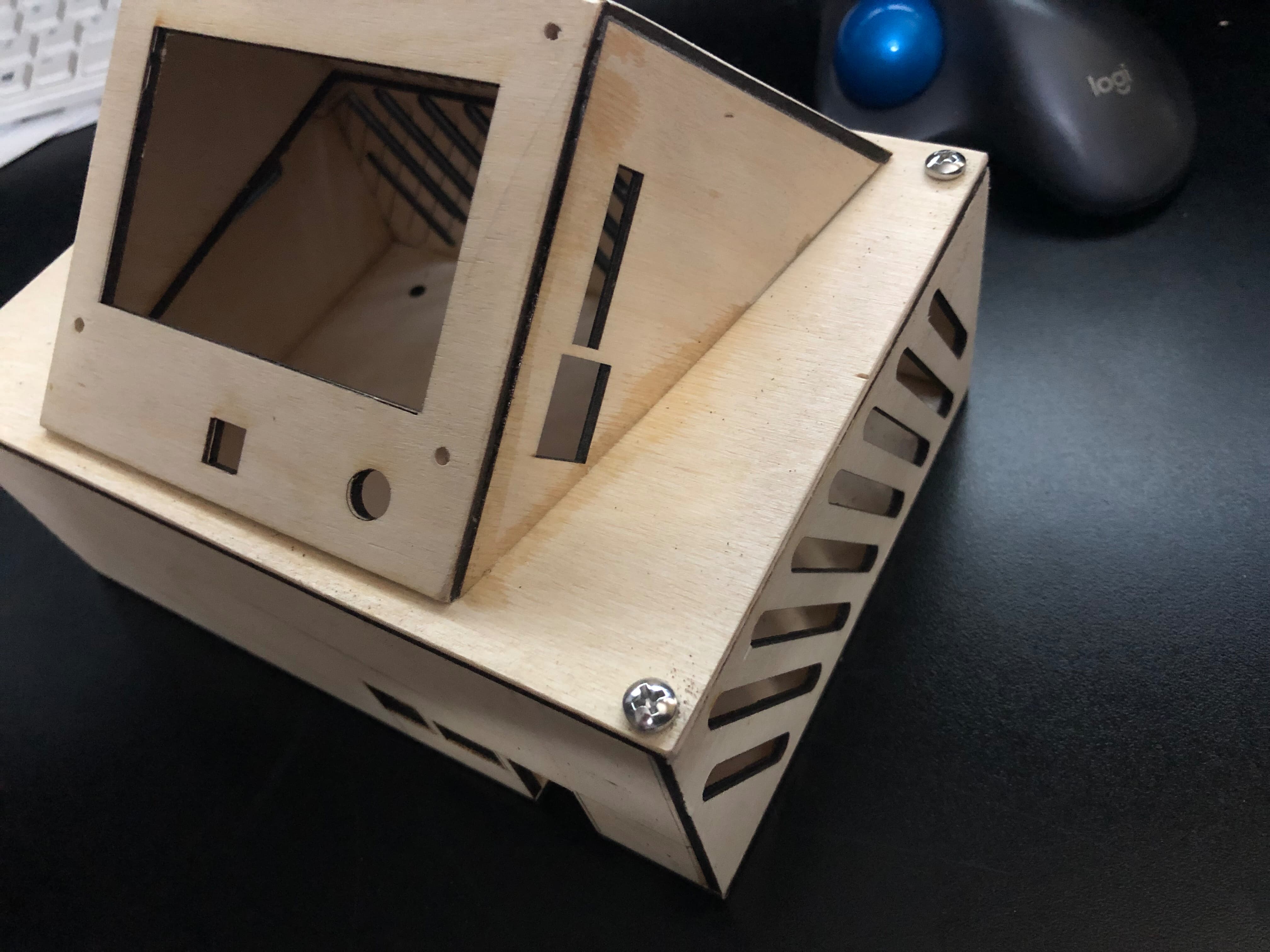
I do not have a 3D printer, but I do have a laser cutter/engraver. So I drew the printed controller box and using 1/8th inch plywood constructed a copy of that printed box.
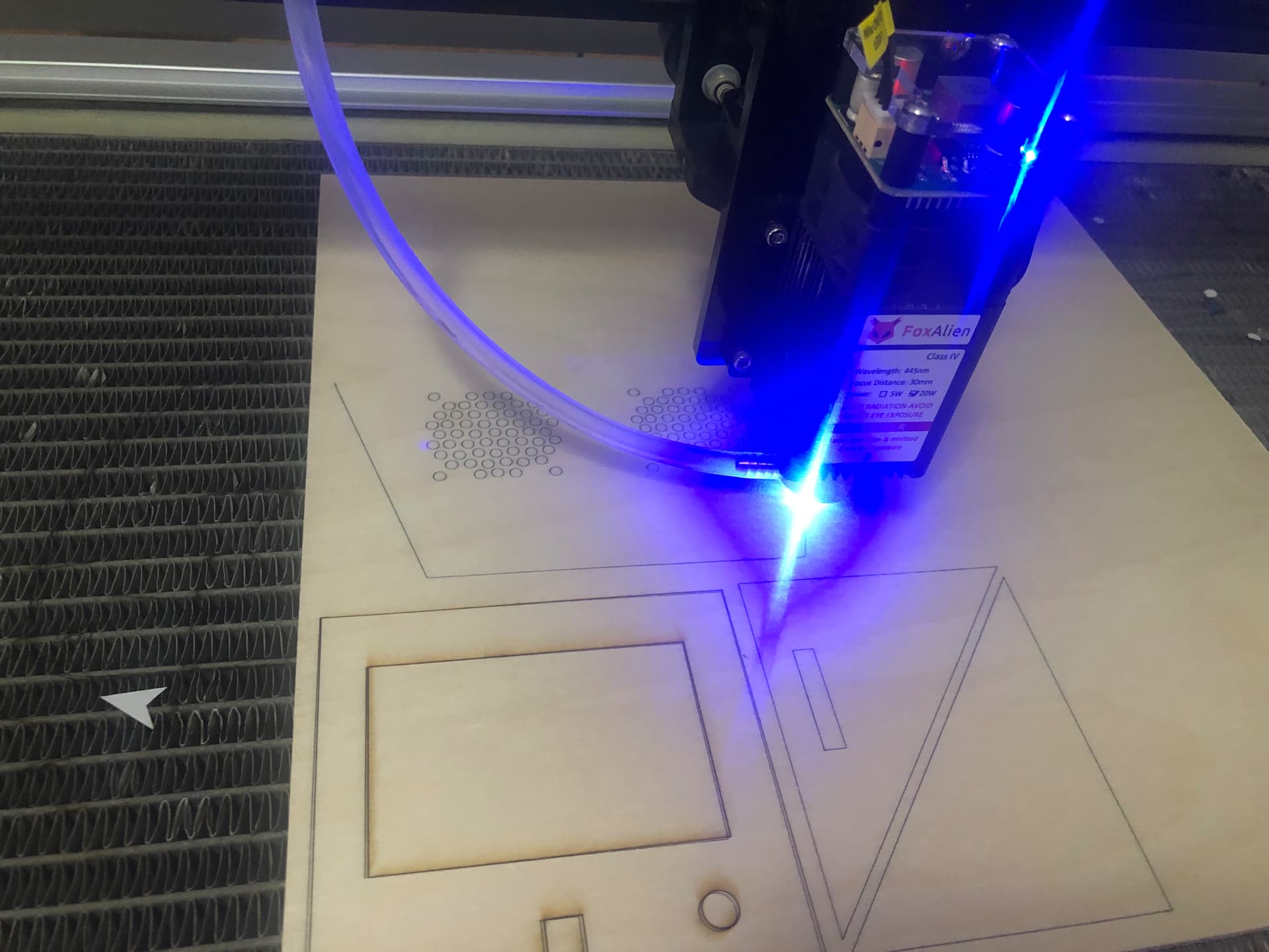
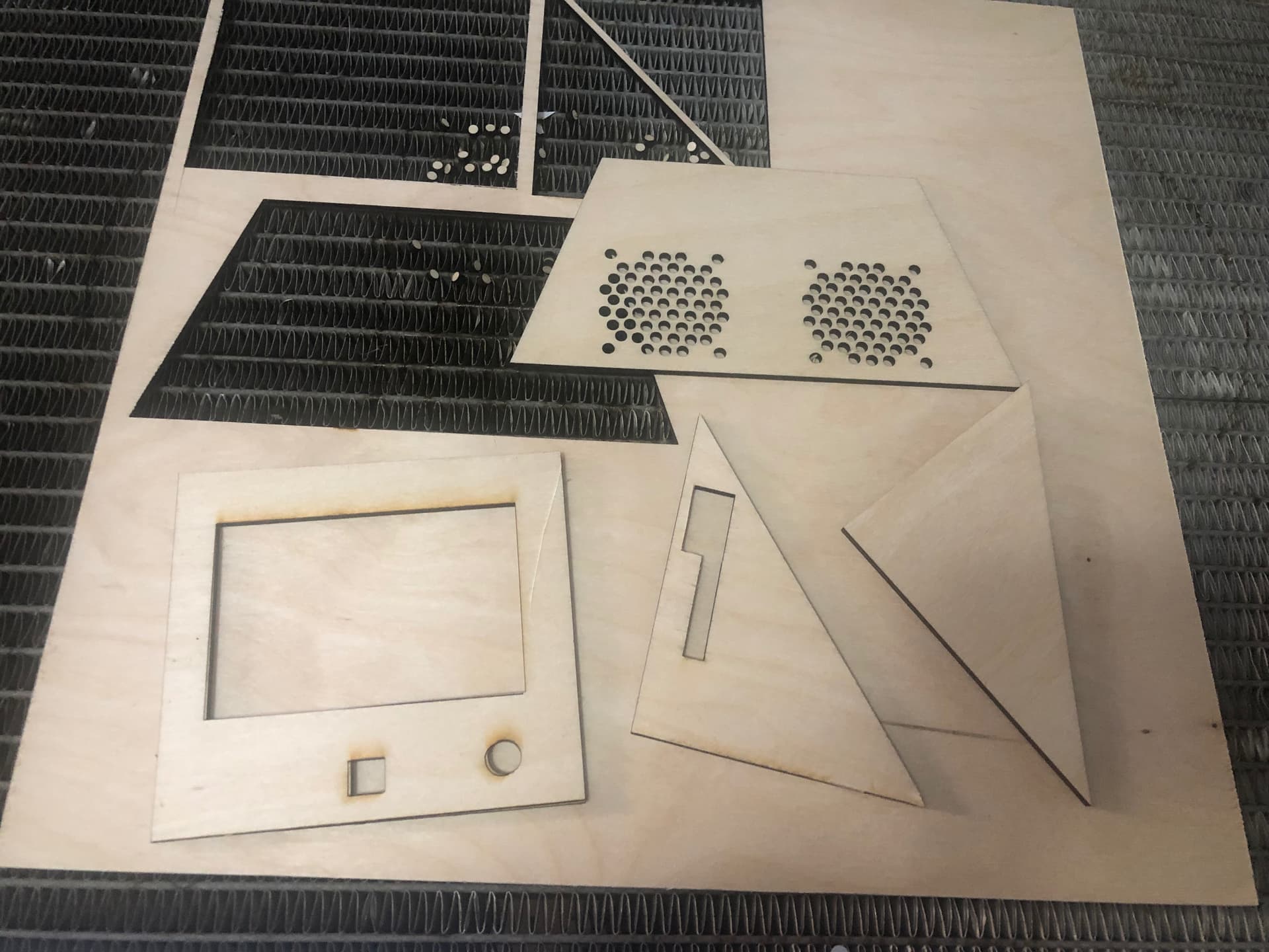
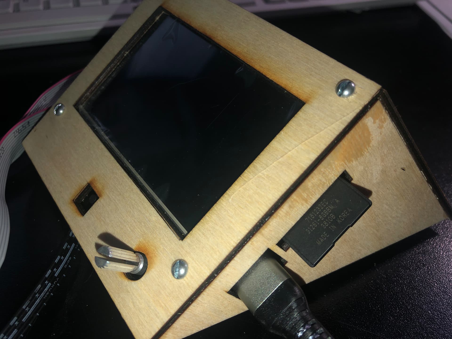
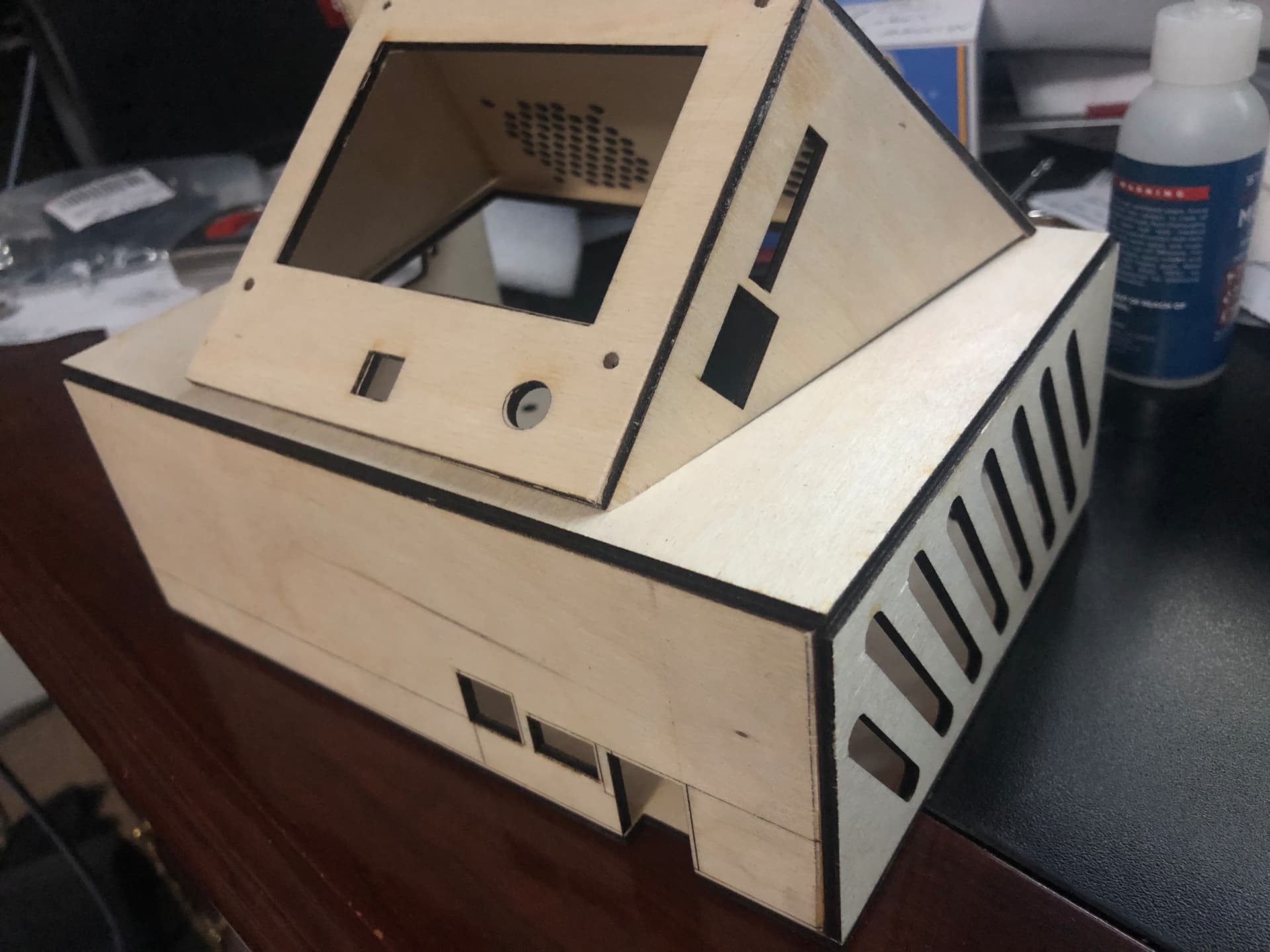
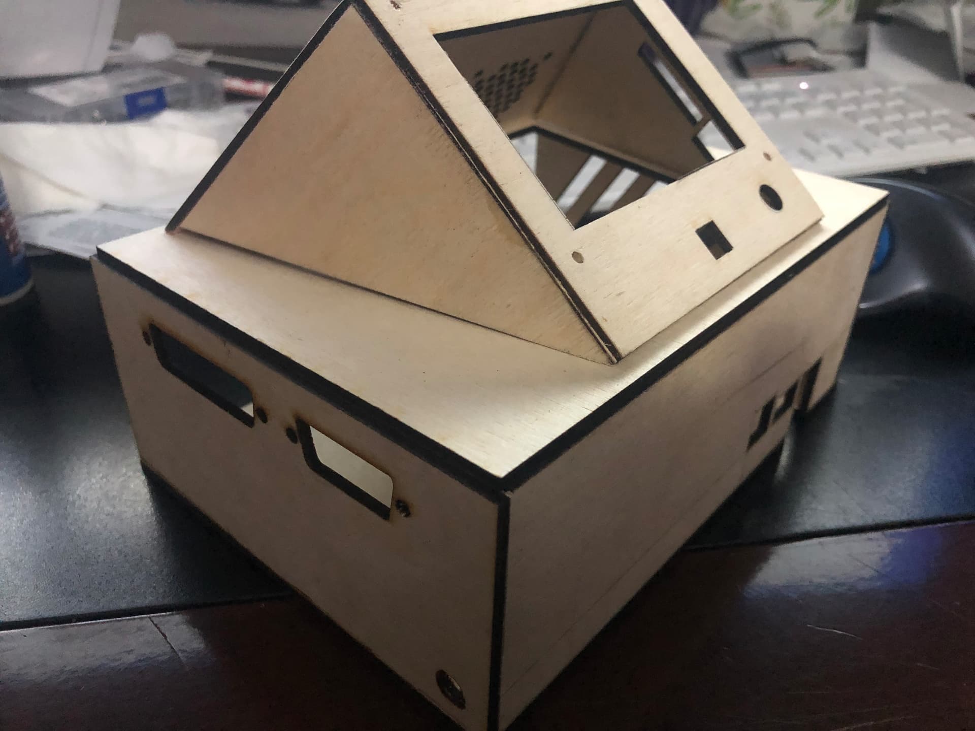
Now ready for sanding and a clear coat to match the mobile cabinet.
8 Likes
Nice ! Is it for skr 1.2 board ?
Would you mind to share the svg/dxf cutting file ?
1 Like
It is based off the printable SKR PRO1.2, 5X 2209 DRIVERS, TFT35 E3 V3 that i ordered with the kit. I shared the files are on the FB v1Engineering group page under files. I actually just shared the lightburn library file that has all the drawings on it. The link is here if you have a FB account and member of the V1 Eng group.
2 Likes
Thank you but arf… i’m away from facebook since 15 years 
2 Likes
I’ll upload to my own website… you can grab it from there.
4 Likes
I hope you were able to d/l the cut file. I just this weekend learned how to export in dxf. That is how new I am to this business. I am having fun and learning. LOL.
2 Likes
Slow progress while I wait for a few printed parts to arrive (for the 3030 extruded frame) i managed to install the cabinet doors. Also need to route the table top for the T-slots.
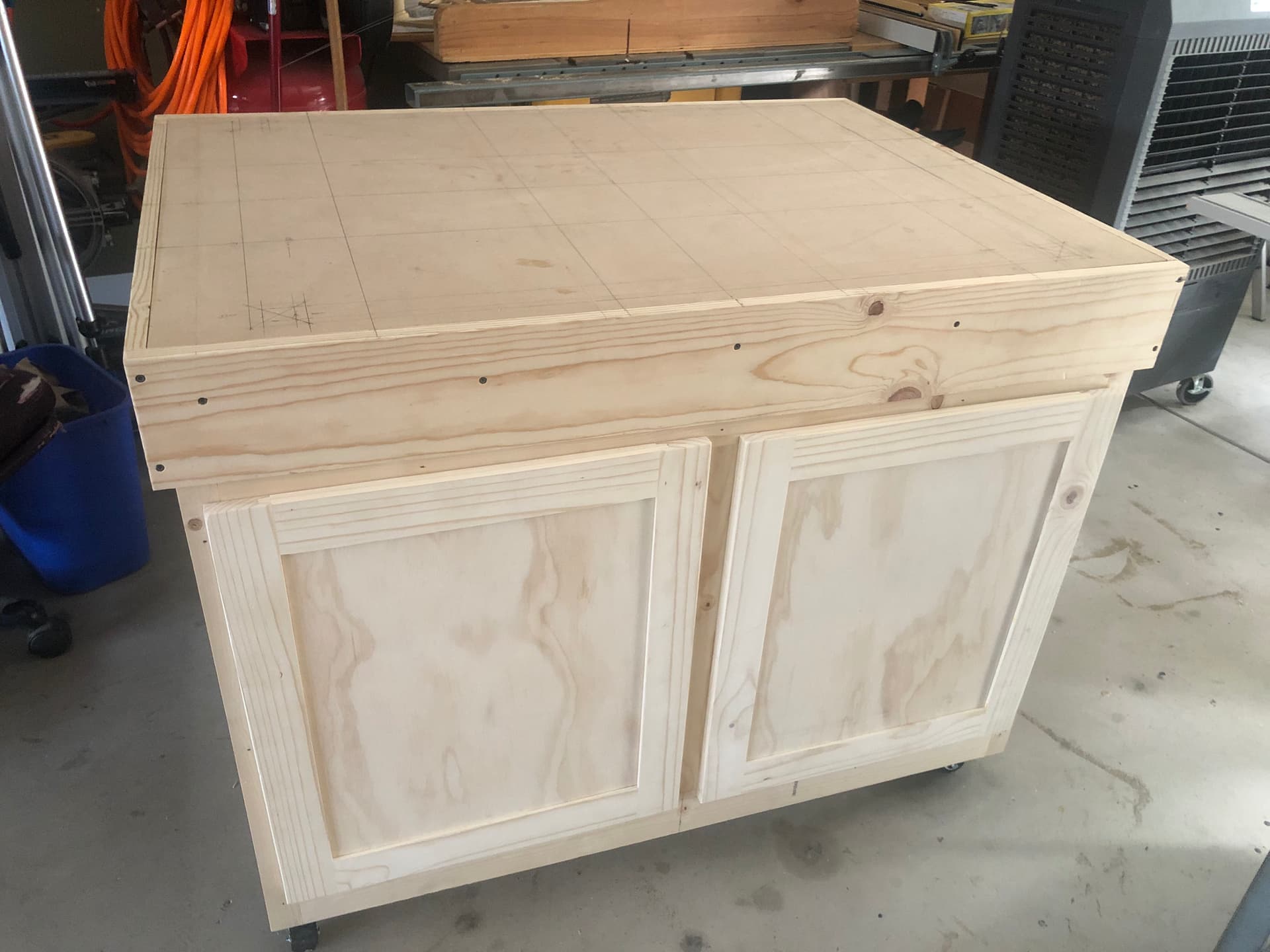
6 Likes
Yes i’ve downloaded it, thank you !
1 Like
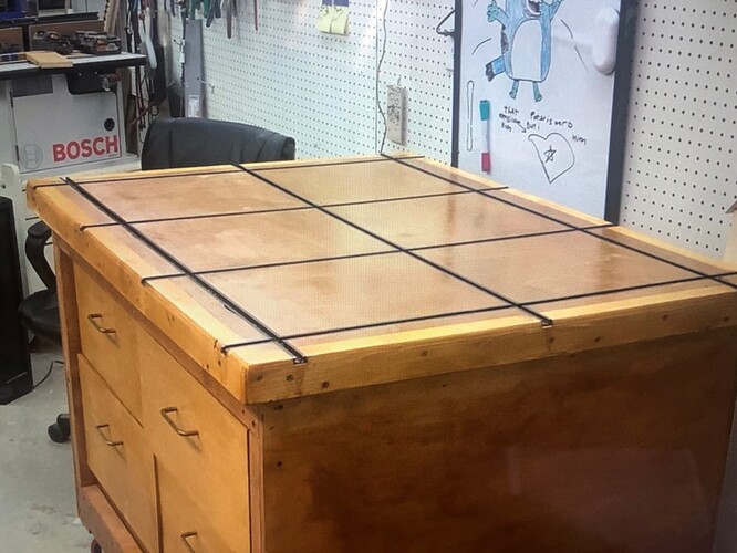
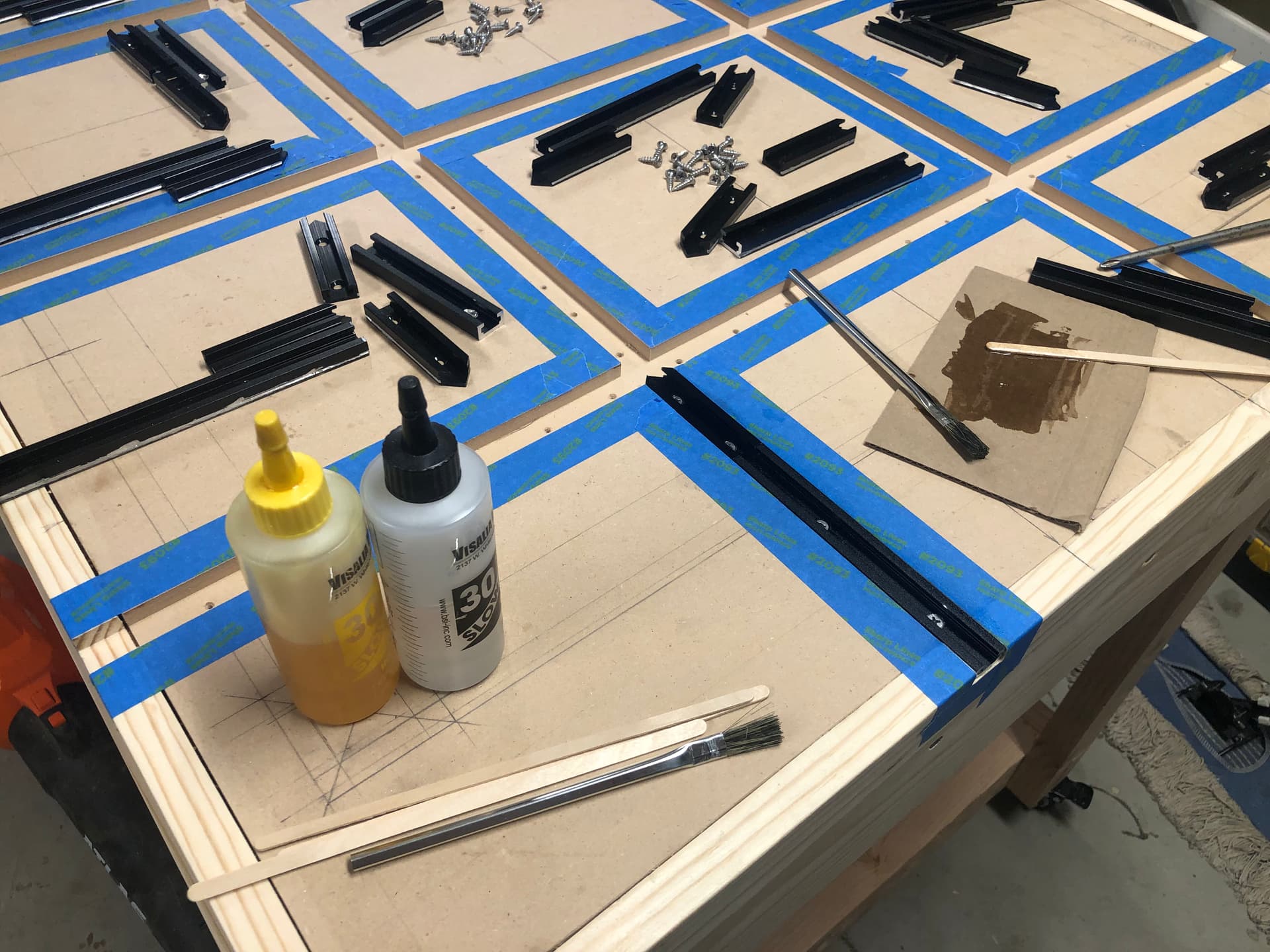
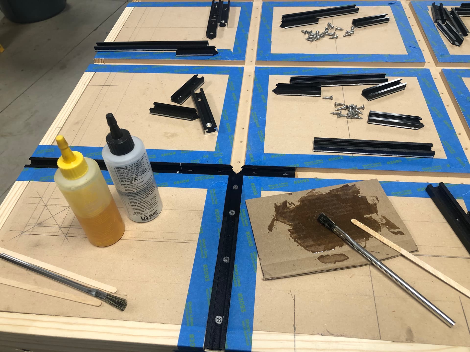
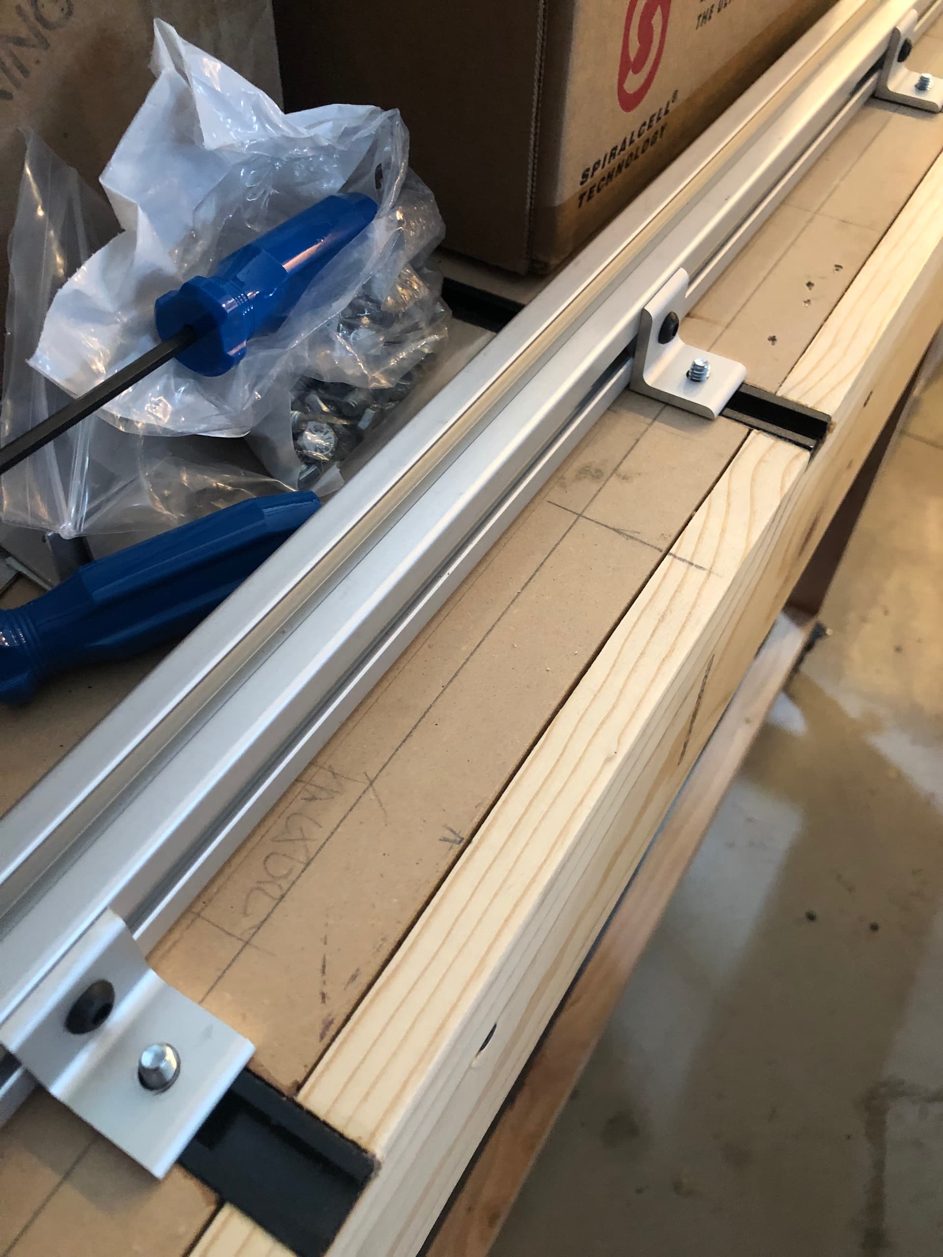
Got a bit done this past weekend… routed the grooves for the t-track.
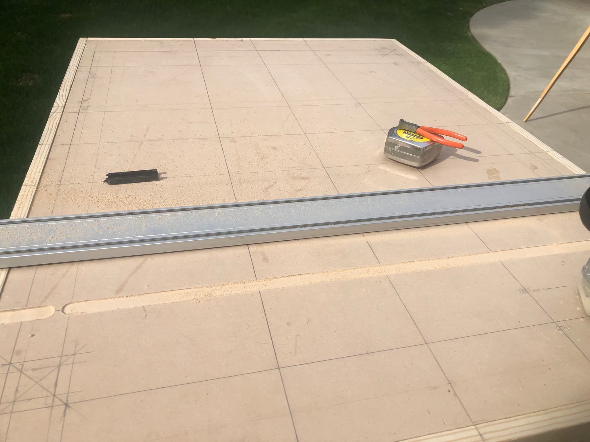
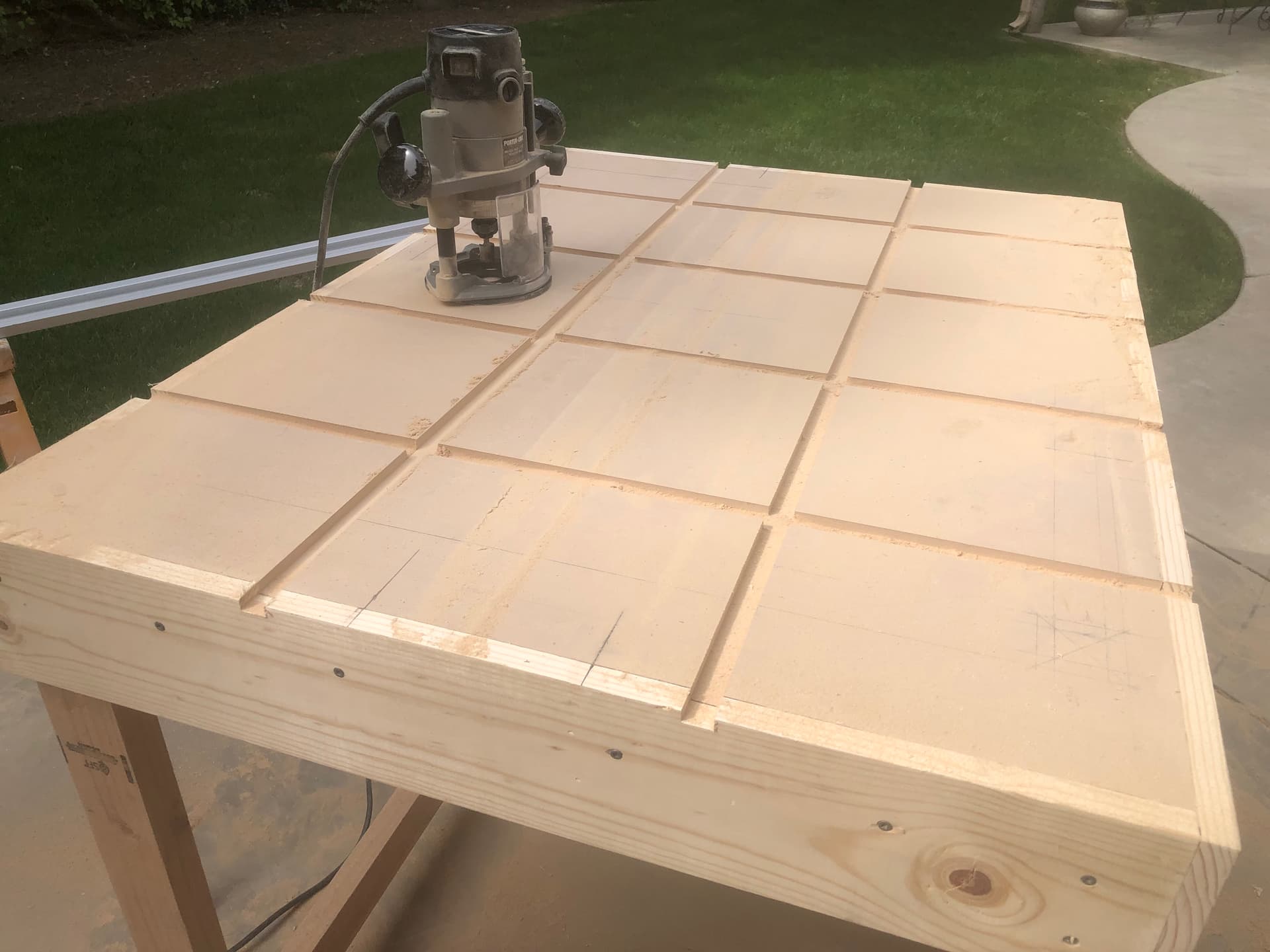
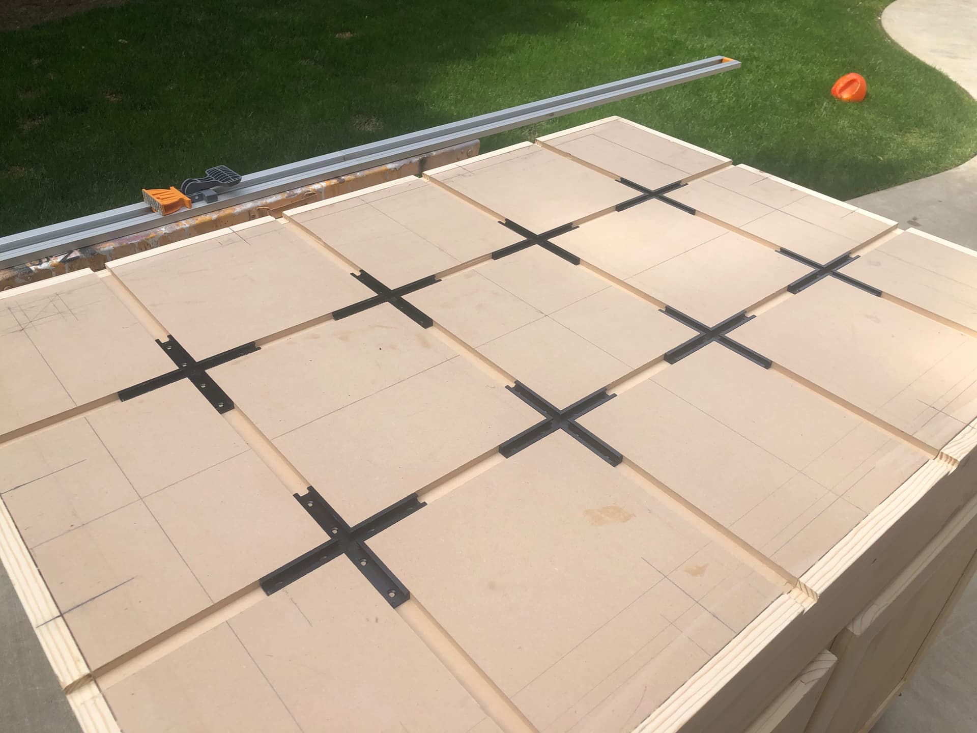
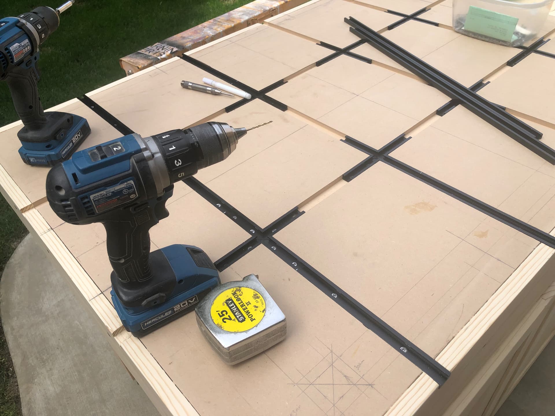
Since I routed 3/8” of the 1/2” MDF, the screws are not going to be enough to hold the tracks in, so I will need to glue them… but the smooth walls probably wont hold well, so i had to cut a slot on each side of each track giving the glue something to grab onto… this will be light duty as it will only hold the 3030 extruded frame/feet of the MPCNC to the table top.
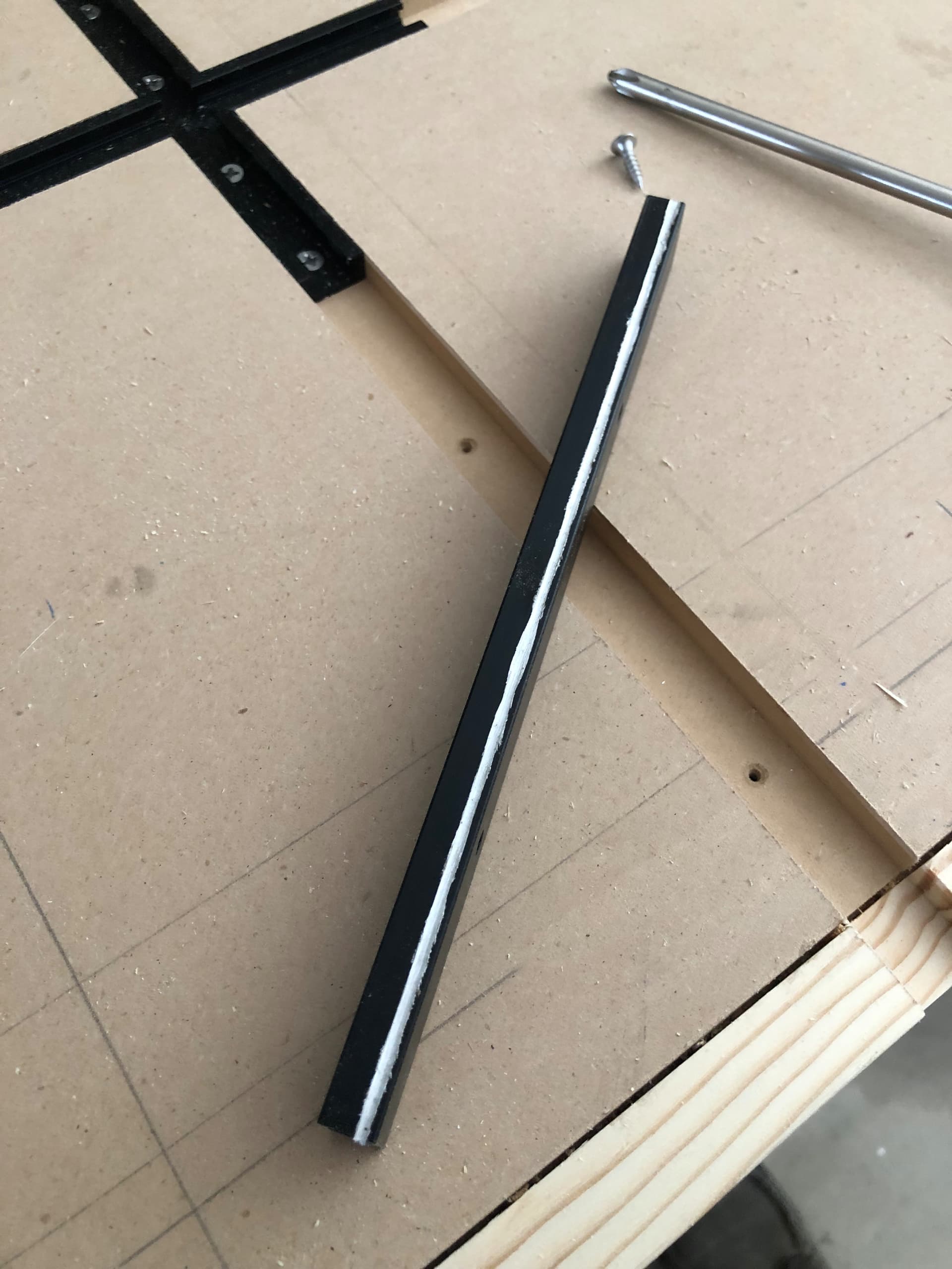
Hopefully these will stay put now. LOL time will tell for sure.
2 Likes
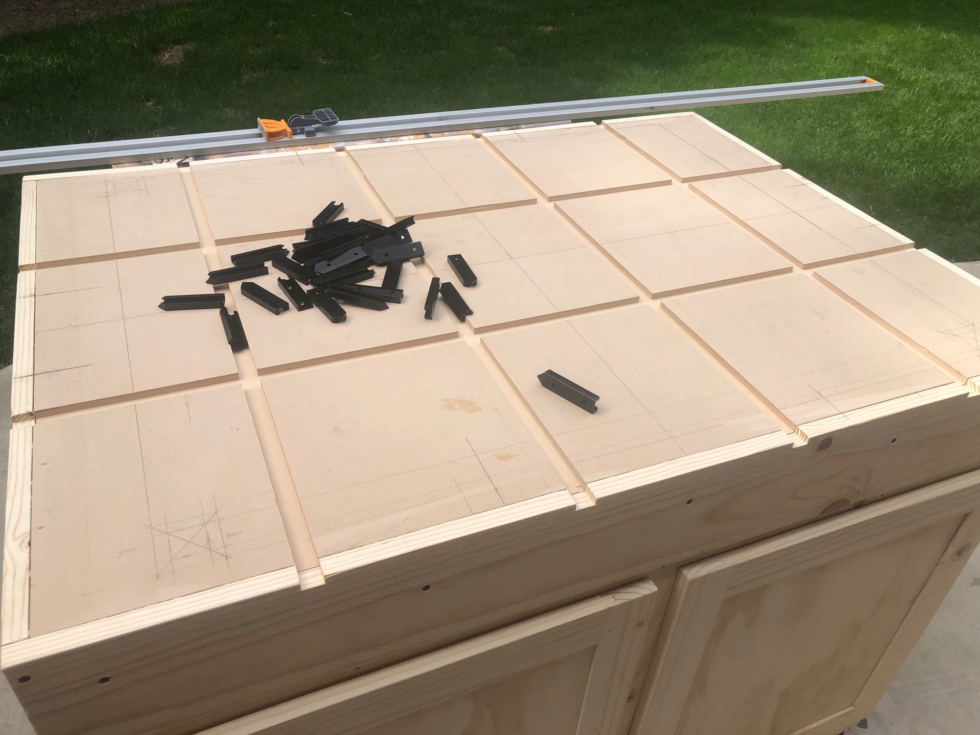
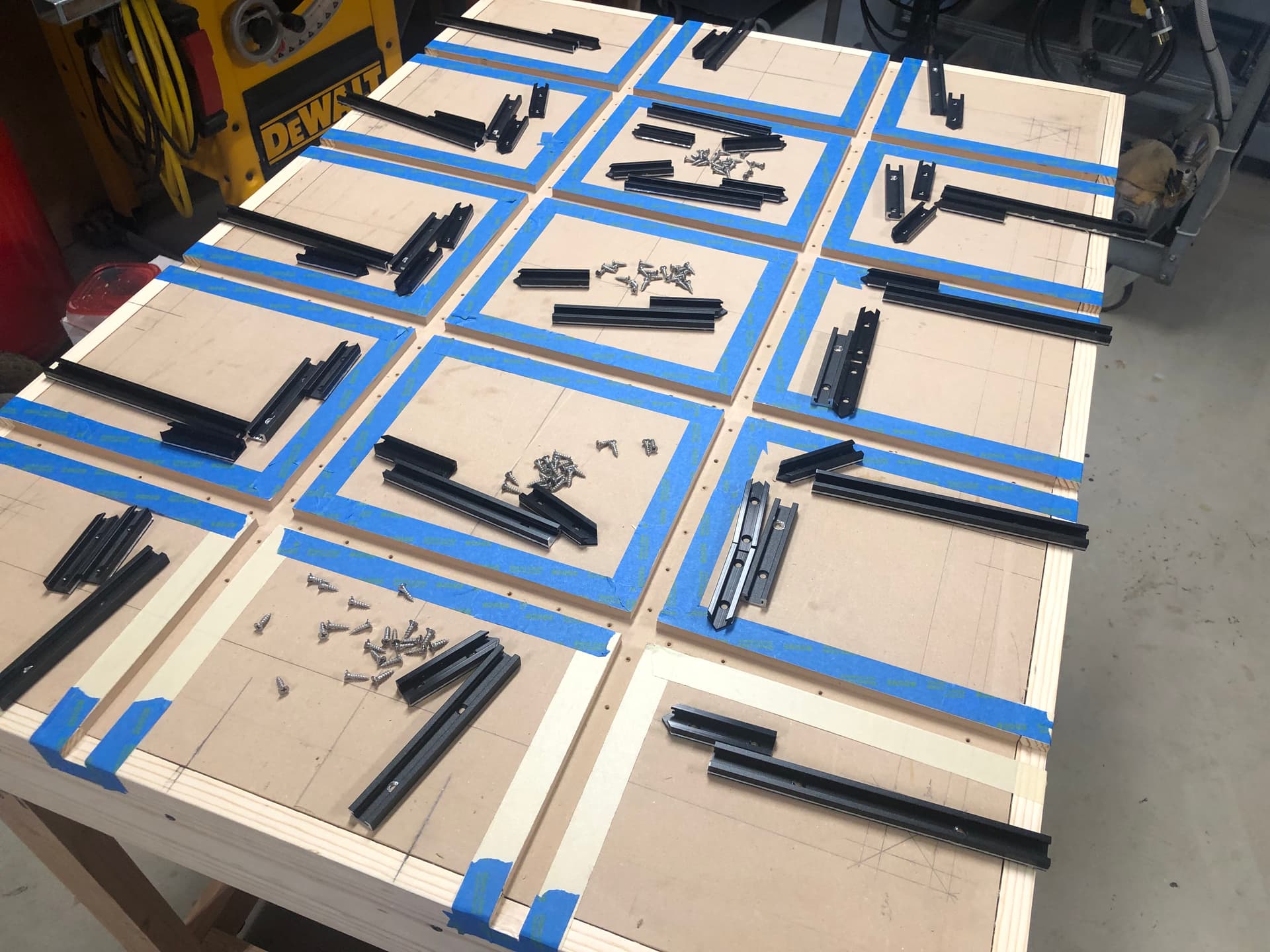
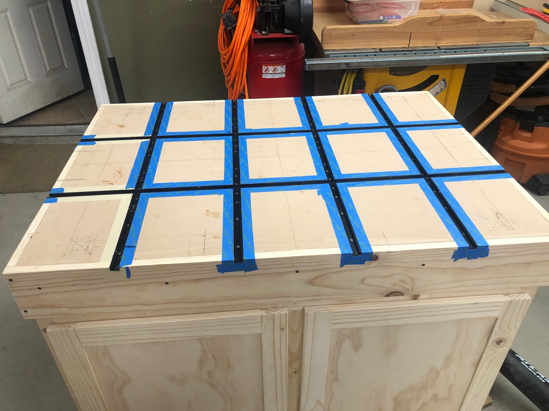
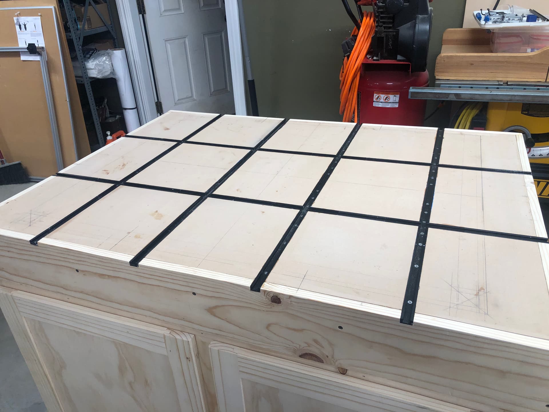
Slow and steady wins the race my wife always says, so a bit more progress I glued in all the T track into the cabinet top, I’m ready to mount the extruded aluminum base for the legs of my MPCNC machine, from there I will begin assembly, wish me luck guys and girls. 
5 Likes
T track looks great! How did the fitment on the 3D printed parts work out? PLA?
1 Like
perfect. thanks again. i believe it takes the guesswork out of squaring and leveling the legs… time will tell LOL
BTW, it is quit sturdy even without the inside corners… may or may not use them. i did put the t-nuts in there in case I decided to use them so I would not have to disassemble. now just making brackets to attach to the t-track
1 Like
I drilled holes in my inside corners to secure mine to table top with 1/4 inch bolts, but they are overkill. I think even the precision cut 3030 and connectors are not 100% square, in my case I never got the gantries 100% square anyway so I’m going to rely on the endstops.
1 Like
It is my opinion that what is truly important here is that the rails be parallel. If they are out of square by a couple of mm, that can be adjusted with either endstops or hardstops, but if they are not parallel, that becomes a much larger problem.
I suppose that you could leave one of the gantry tube clamps a little loose, which would allow the gantry tube to slide a little on that side, while maintaining the motor positioning in the axis. This would allow for a little bit of unevenness, or maybe a slight bend in one of the rail tubes, but I’d personally MUCH rather spend the time making sure that those are parallel. I spent the majority of my time with the legs doing that with my build.
Of course having everything square is very nice, and makes a lot of the rest of the setup much easier, but the basic machine operation will still go smoothly if you have a slight parallelogram with the X and Y rails.
4 Likes
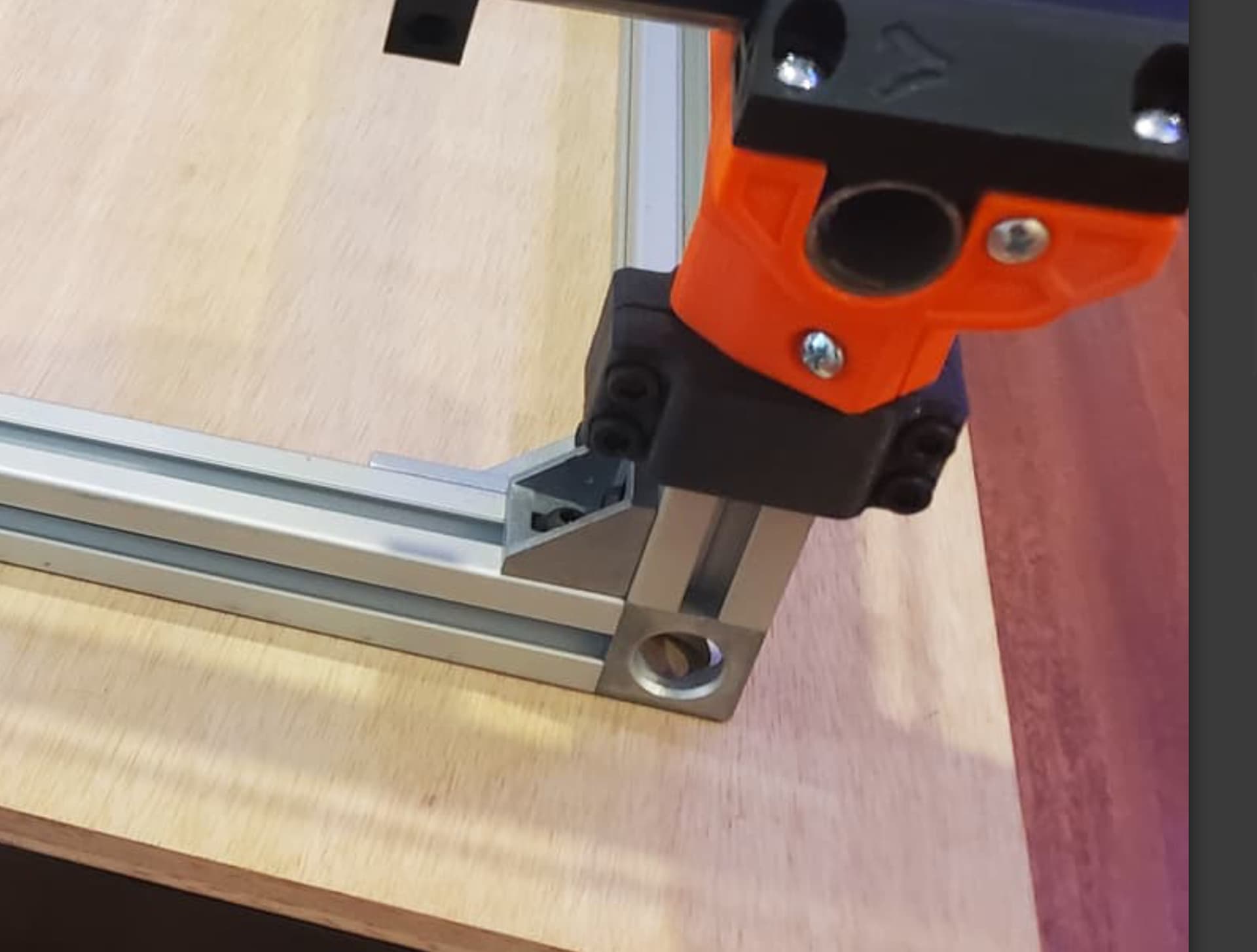
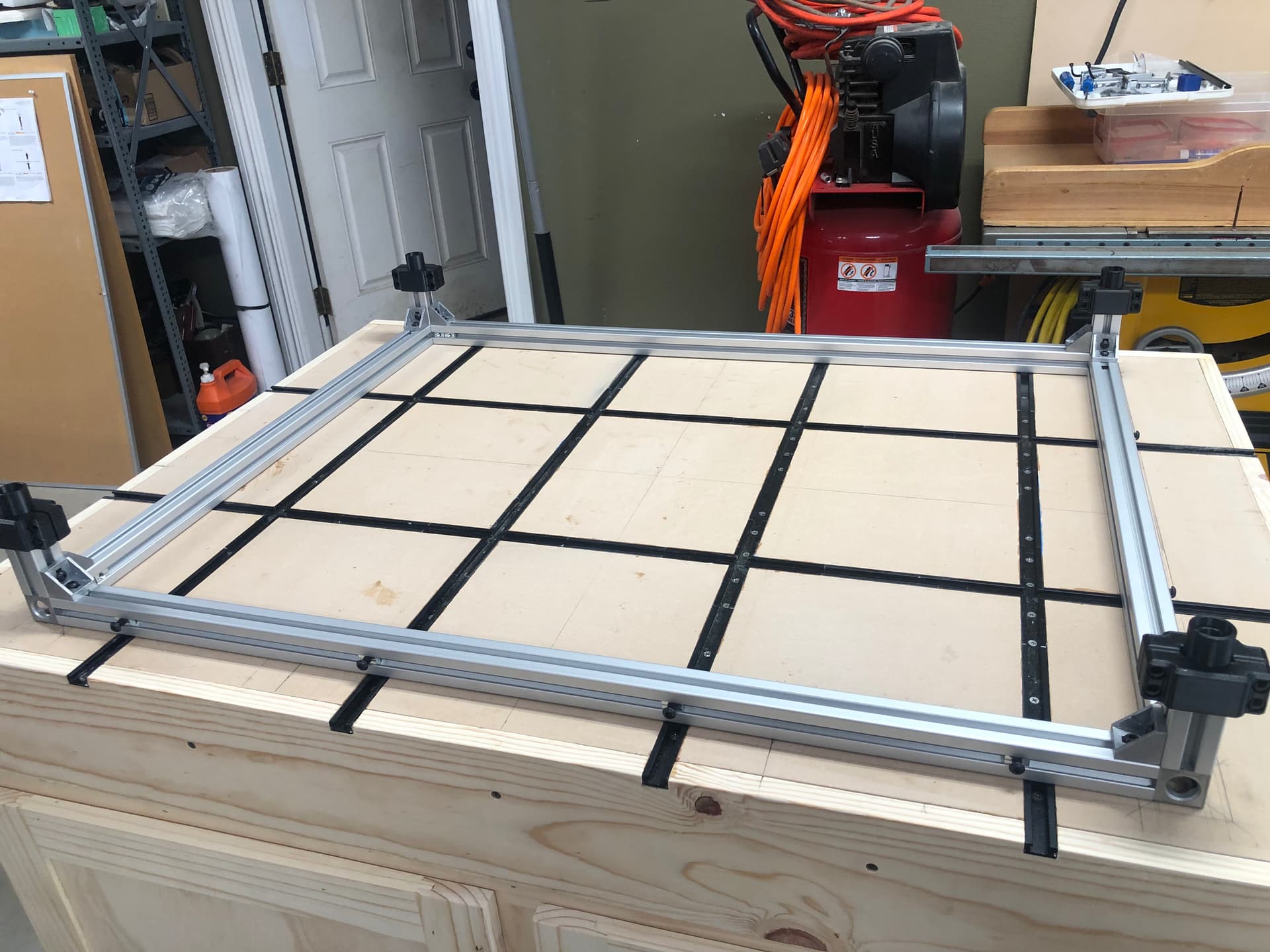
So i began bolting down the frame to the table top. I measured the width and length and they are within a 1/32 (or on the nose). The square (corner to corner) was also same in both directions. I don’t think I could be any closer to square or parallel with the frame… hoping it translates to the rails. 
2 Likes
That’s such a satisfying feeling. Knowing you don’t have to redo anything. It’s always nice to nail it on the first try with little to no adjustment needed.
2 Likes