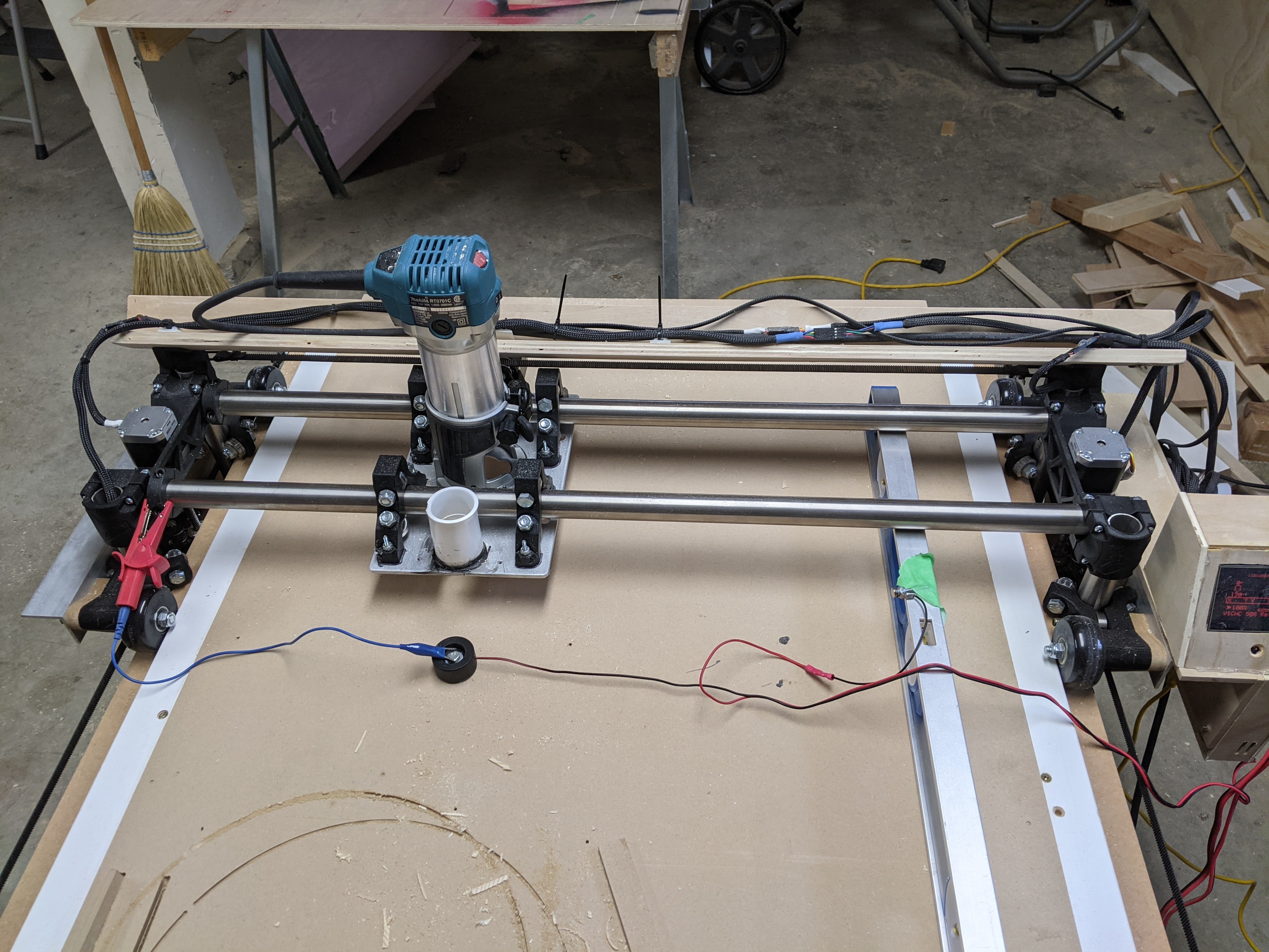
I was having trouble the other day with surfacing a part! The solution appeared to be to check if the machine was trammed! Well it turns out that the tramming is the issue. The question now becomes how do you tram the lowrider? There isn’t any adjustment method that I can see. The rear X axis tube definitely sits lower than the front.
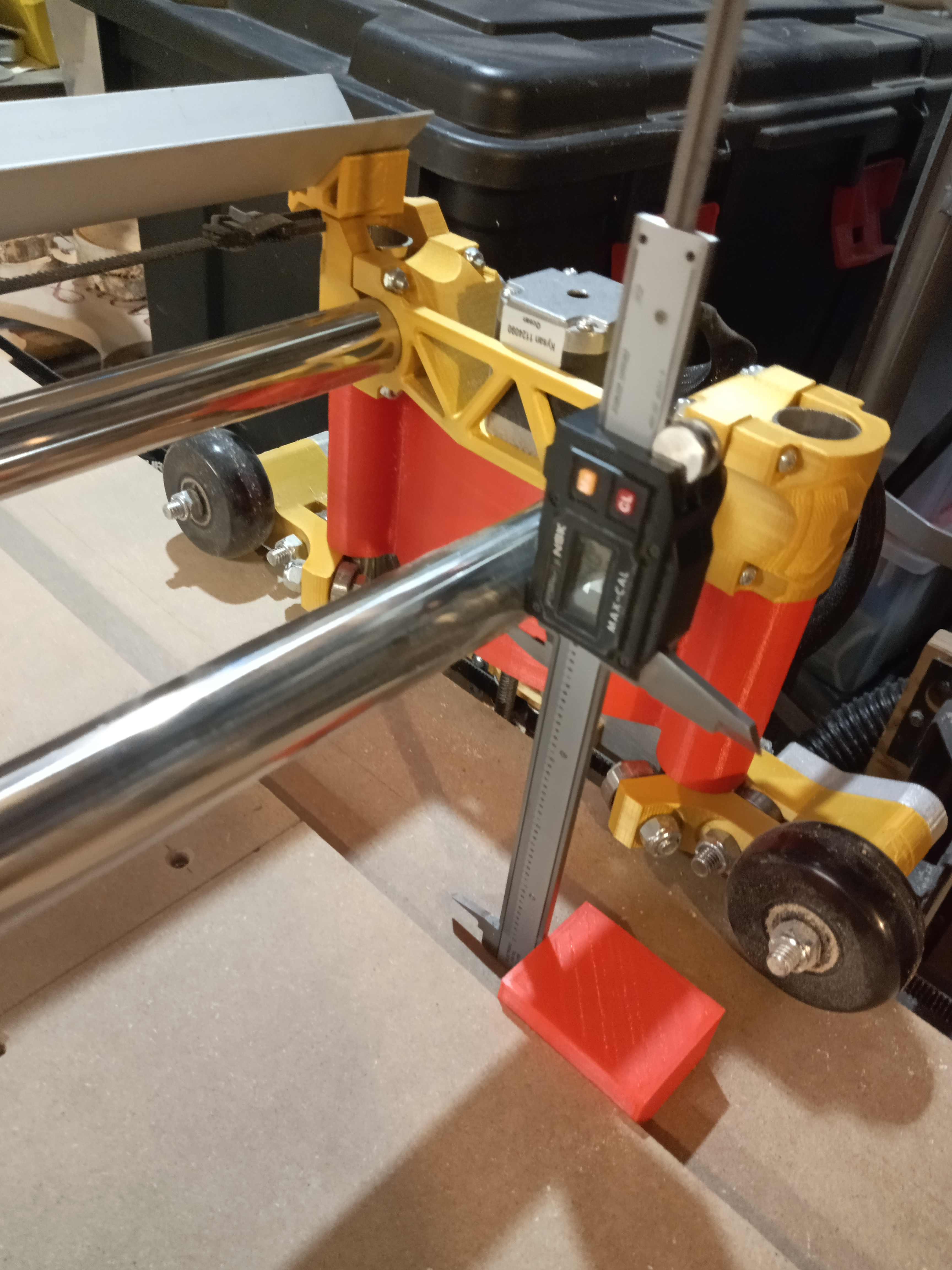
I made a holder for my calibers to measure the differences:
Based on the above it would indicate that the left to right difference is very minimal and acceptable to me. It’s the Front to back that is a problem, how do I adjust this?
Interesting problem. The only “adjustment” available, as far as I can see, is to loosen the YZ Roller assemblies and try to “tweak” them a bit in the proper direction (front lower and rear higher in your case), and re-tighten. The bolt holes in the Y plate were certainly not an interference fit on my Lowrider, so I suspect there is room for a tiny bit of adjustment.
Out of curiousity have you tried multiple measurements with the wheels in different orientations? Slightly out of round wheels could cause this too, but the error would vary with rotation.
I would think you could adjust the tightness of the four screws on your z tubes. Tighten the top and loosen the bottom should make things tilt. Maybe? I haven’t tried it but will be trying this as well soon.
I may have to do this although removing the whole assy to get at the screws wouldn’t be my first choice and it would be a crap shoot to get the wright size shim. I would also be concerned that the fix would be temporary as for whatever reason it’s off now it could shift again.
I have been thinking through a more elegant solution but I have not had time to implement it. Threaded inserts with grub screws in the router plate. However, I am not sure if the thread pitch will be fine enough to be practical. Could be finicky…
That is interesting. There is a lot of vibration there too. So they would need a nylock or a second lock nut.
My first though is: Is there tension built up in the two longest tubes? Maybe they are twisting against each other and you’d get kind of a taco. I would loosen and then tighten the mounts holding those together to make sure they are at rest. I would do this before trying any other adjustments anyway.
I think shimming or adjusting the router plate or the router mount is no good option to solve that. If the Z tubes are not rectangular to your working surface, your Cuts will have small steps on the side walls or with a full depth finish cut the dimensions will me smaller at least on one side of your part.
I would say loosening and retigten all lower Z rollers when the gantry is resting on two parallel blocks on the working surface should solve your problem. If not, make these bore holes in the Y plate bigger and repeat the process
I was responding to Rich. If you were to ignore the tubing and just tram the router with shims, you would be able to work just fine. The trouble would still be there in very deep cuts.
By all means, fix the root issue. But if that ends up being difficult, then shimming the router will give you most of the benefits.
I agree Jeff, root issue has to be solved it out will just appear again at some other point. The tough part is finding the spot. The machine has been working fine, just when I tried to surface a part is when it shows up. I could easily sand out the issue on my part but I want to get to the bottom of it.
I’m just in the process of tramming mine. I put a level on the table and attached my z probe to the level and the rail. I then probe the z without an offset so it stops right on the level. Then I use a feeler gauge to check the front and make rails to make sure they both touch and there are no gaps. To adjust the gaps you can adjust the four bolts that hold the z tubes to the x tubes. Tightening the top and loosening the bottom causes the rail to move down to the table. Now that I know my rails are true I’m moving onto the router itself
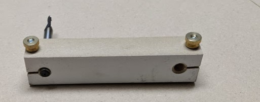
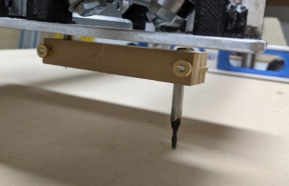
So after setting up the rails to the level, I checked perpendicularity of the router using a method that has been posted here before, I just used some “learner” bits and a block of wood with a clamp screw and chucked it in the router.
I lowered it to the table and checked the gap under the bit, there is lots of flex in this setup so its pretty heard to measure. From what I could tell I had a difference of about 0.05mm in the Y direction. Since this is actually 0.05mm over something like 4" (diameter of circle created by the bit) I was more than happy. I had more issues in the X direction. I tried adjusting the tension on the X roller brackets, that did not really do anything. Then I realized I could just shim my parallel blocks that I use to set the Z initially. These are just two pieces of mdf trim that I put on the spoil board and then lower the X rails to that. I don’t zero it on the 3d printed parts because those parts are not critical and will have deviation.
Long story short after adding tape to the parallel rails I was able to level out the X.Having the bit lightly touch the surface makes a faint scratching sound on contact. Spinning the arm 360 degrees needs to make a consistent scratch sound. I took points throughout my table and it all sounded the same… good enough for me.
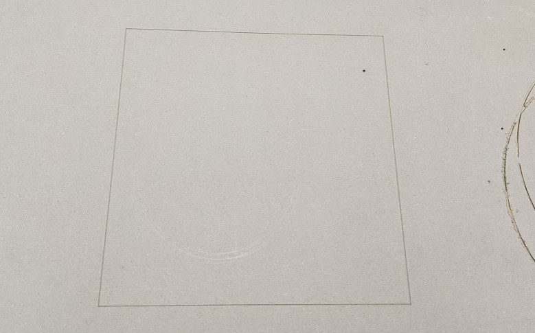
Ran some test cuts, 60 degree V bit, 1mm into the surface and a 300 x 300 square results in measuring tape perfection corner to corner and consistent groove width indicating everything is running true.
I have never surfaced my table top or my spoil board, they are 1" mdf and 3/4" mdf on top with the 1" board just floating on the legs to keep it flat.
I will try surfacing some signs soon, I had some issues with signs on Friday and I think my issue was that my rails were significantly out of true. Hope this helps you get yours dialed in as well.