I had previously done a different post about how I trammed my rails by using two metal levels and adjusting the four XY brace screws at the bottom of the thread here How do I tram the LowRider - #20 by RobP.
Well, I have changed up some of my components to aluminum so I no longer have the ability to adjust my ZY braces so had to find a different way to tram it. I can’t take full credit for it because I saw a youtube video on how a guy did this on a big CNC but I am taking credit for not having to buy a $100 + traming gauge.
Note: I have a spindle clamp for my router but the same principles will apply to the standard mount that comes with the router.
My steps were as follows.
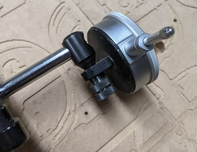
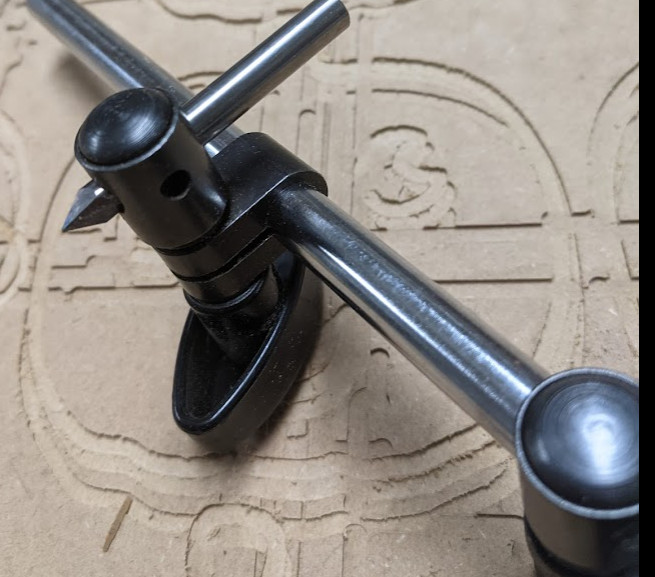
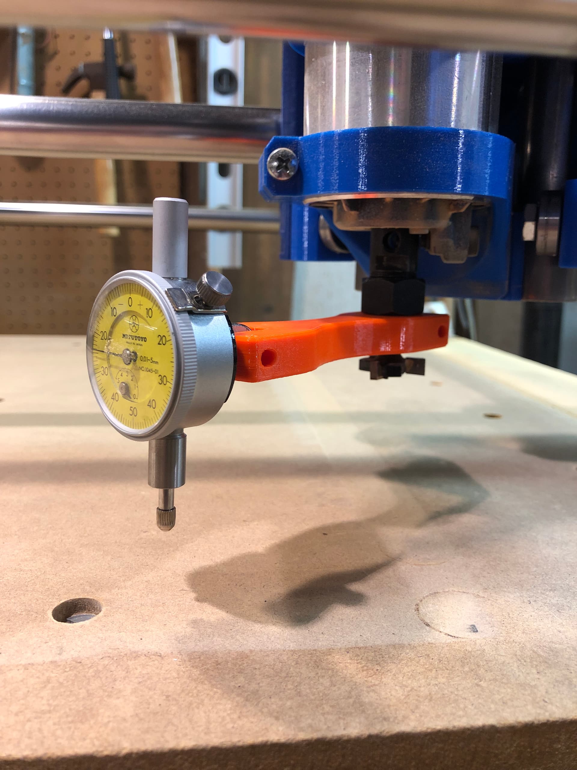
I used a magnetic base dial indicator, took it apart and played with the different clamps until I got a combination that would allow one end to clamp onto a 1/4 endmill and the other would hold the gauge.
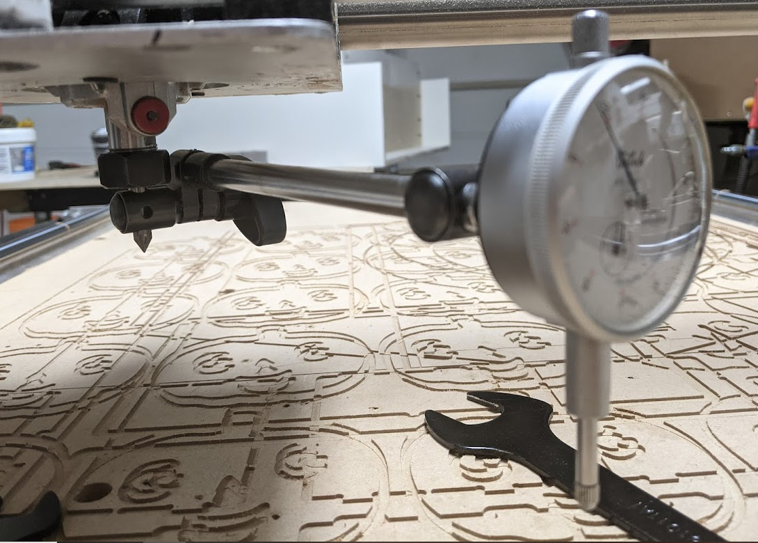
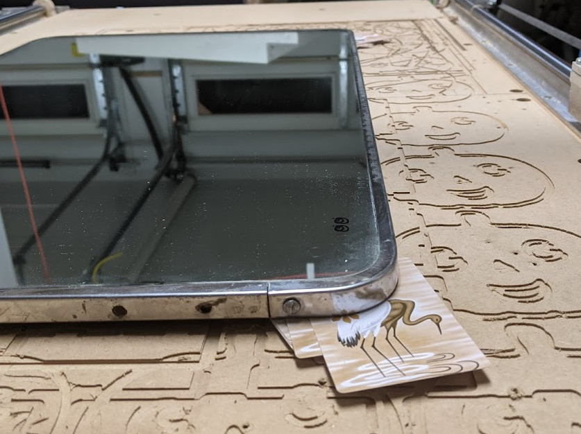
I used an old vanity mirror because I needed something completely flat and smooth. I put this on the spoilboard and probed one corner with the dial indicator. After setting Z to zero and the dial indicator to Zero I probed a square and shimmed the mirror with playing cards until all corners were reading Z on the dial indicator. Note: Don’t drag the dial indicator as it will spin the chuck and then your runout/angle of spindle will come into play.
I then set the router to the middle of the mirror and spun the gauge and boy was mine out of wack. I was reading a 0.050" deviation from one side of the 7" swing diameter to the other. I loosened the four screws that hold my router to the 611 plate and noticed one side was not able to clamp all the way down. After some messing around I fixed the gap. I still had some deviation when swinging the gauge so I loosened them up again and then used aluminum foil (the stuff you bbq with) and folded little strips together to make shims. I over compensated where needed as there would be slight compression when tightening the bolts again. After a bit of messing around I now have a deviation of 0.001" on a 7" swing diameter. This is well within the margin of error of this process. Also a light touch on the top of the router can swing the gauge quite dramatically.
I’m curious to see my improvement on cut quality, I never really had an issue but I seem to have a high pitched squeal when cutting with carbide and I always wondered if it was because the router was not perfectly square.
Next step is going to be to surface my spoil board with a 0.75" flat bit I have laying around.
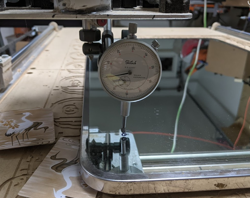
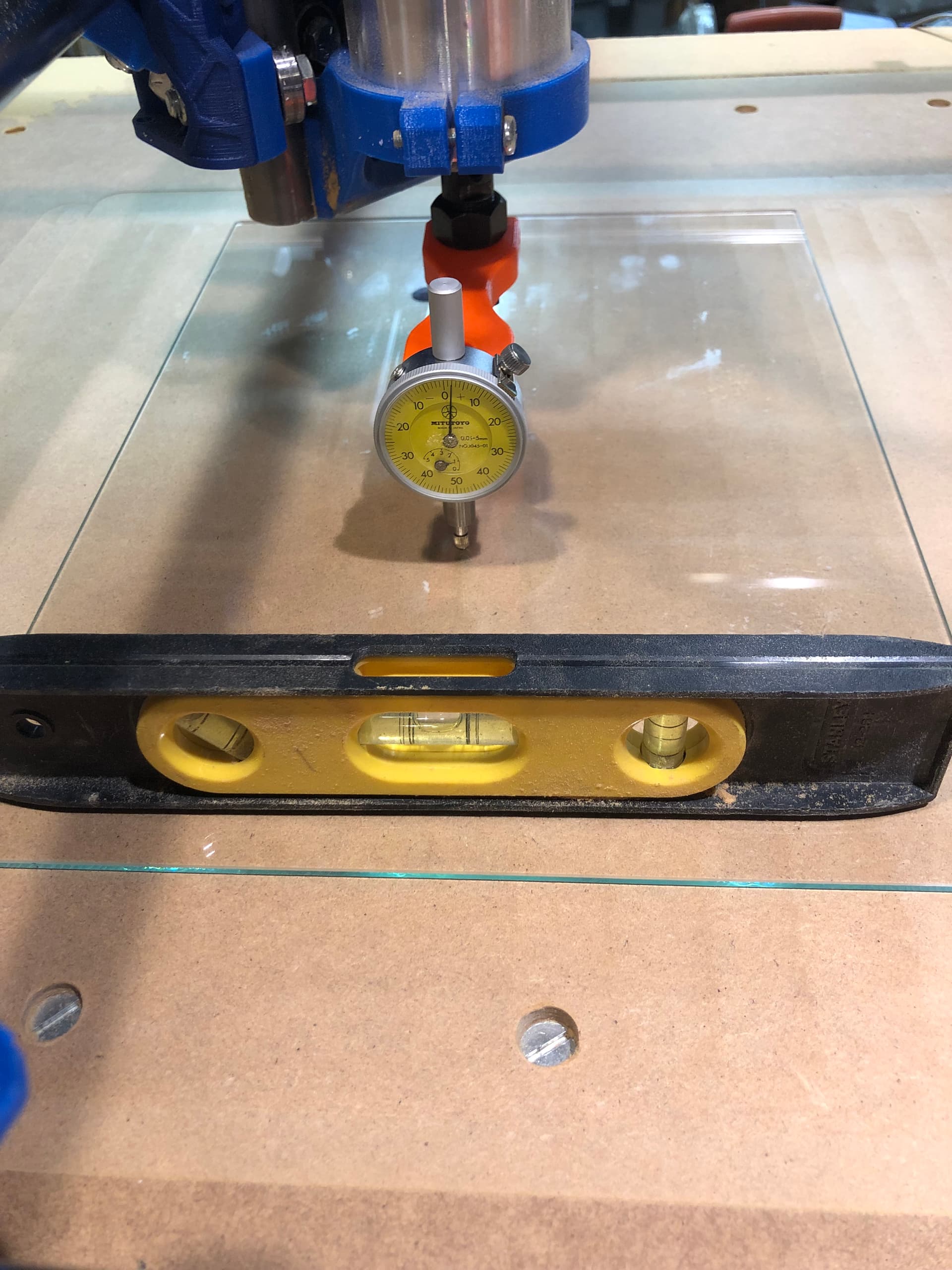
So I made my first attempt at surfacing my spoil board and found the alignment of the Z-axis to be in question. Found a tool on Thingiverse and modified it to work with a 1/4" shaft bit and my dial indicator. I had previously salvaged some flat glass from discarded Brother printers and used one as a smooth/flat surface to reference against. First checked the rails to make sure they and the spoil board were all reasonably level then checked the glass and it too was level. Rotated the indicator and found big difference in X plane that will need some correction. Y plane not so much but will work to get it better with some adjustments to spindle mount.
You may not like this, but shimming with small layers of plastic (like a cut up coke bottle) can point that router straight down. It doesn’t have to be perfect (there is always flex in every CNC machine).
You might want to just probe and shim your glass instead of comparing it to a level. I doubt your level can read very accurately when compared to a dial indicator. Just make sure you are not getting pushed in the wrong direction by an incorrect starting point.
Yes plastic shims work, playing cards or pieces of aluminum foil work well too depending on how much you need.
Thanks for the advice. For clarification’s sake can you confirm where the shims are best placed?
I’m assuming between the spindle body and the mount but want to make sure it wasn’t meant between the mount and the rails.
Does it make any difference if you shim half on the top and half on the bottom (opposite side of course) vs all in one location leaving the other mount without shims?
Ended up probing the glass and bringing to nearly even on all 4 corners of a 200mm grid. Used the macros in Repetier to make it easy to go to the opposite corners really easily.
Centered spindle and swung a 200 mm dia. circle. Reduced out of plumb to less than 0.2mm from one side to the other in both X and Y. Less than 0.1 degree I’d say should be good enough.
Installed 0.66mm shims on bottom mount X direction and 0.22 shim on top in Y direction. Used Vinyl Graphic film stock I had lying around.
Took a little while but I think it think it will be worth it given where I started. Next cut should tell the tale.