Also, I’m not tied to any Firmware or software yet. I know the Rambo board came with Marlin on it. I’m familiar with Marlin from a 3d-printing point of view but not milling. I use Fusion360 to model, PrusaSlicer to slice and send to Octoprint and print on an Prusa MK2.5s MMU2s. The just now mentioned workflow works well for me and I understand it.
Milling on the other hand is new. I have experience milling with an old Bridgeport about 20 years ago so I get the idea… just need more experience with CAM. What workflow and software do you recommend for the Rambo w Marlin? I’m also open to switching to a different controller board if that gives me more options.
If you are looking for a joystick pendant, there is built in support in Marlin; it just needs to be enabled. All it takes is a 3/4-axis joystick, a push button, and some wiring to hook it up to the Rambo board. The joystick wires directly to the Rambo board along with the enable switch. Then you update Marlin to enable Joystick support, tweak the range values to match your hardware, and it is good to go.
For my MPCNC, I combined a couple approaches using the joystick and an Arduino Nano I had laying around to create my controller. The joystick and enable button are wired up as described above. But I also included an Arduino Nano that is wired to the Serial port of the Rambo and a couple other buttons to allow me to send code commands from the pendant for common setup tasks like homing and resetting coordinates.
Take a look at the software workflow. CAM is like the slicer, which is geberally Estlcam or fusion (used to be anyway). For design, the main distinction is between art and functional objects. For art, inkscape and for functional stuff, onshape, freecad, fusion, librecad. Anything you want, really. Typically dxf is the format for most projects and stl is only for 3D stuff, where it moves XYZ at the same time.
Thanks for this… do you have a wiring diagram for the Nano? Do you know how I’d be able to get the jog wheel to work too? the idea is to use the joystick for larger moves and the jog wheel for smaller incremental moves.
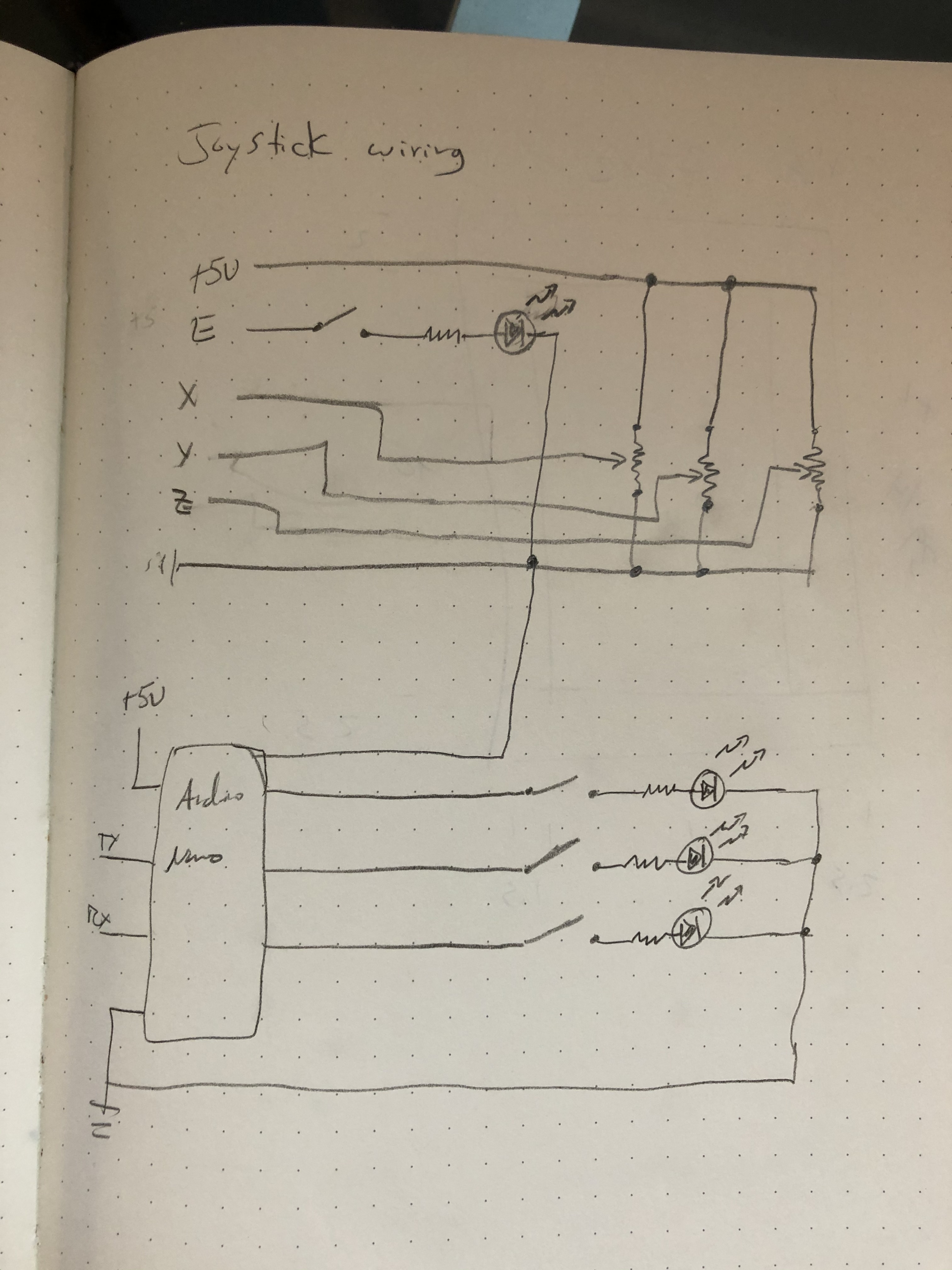
Here’s the wiring schematic that I used. The top set of wires attach to the Rambo board in the typical locations. The bottom wires power the Arduino and hook up the Serial 1 pins on the Rambo, which needs to be enabled in firmware.
The Arduino sketch is fairly simple as well. It checks for the enable button being closed and once of the other buttons being closed, then sends the appropriate GCode down the serial lines to the Rambo. I’ll see if I can dig it back up and post it to GitHub for you.
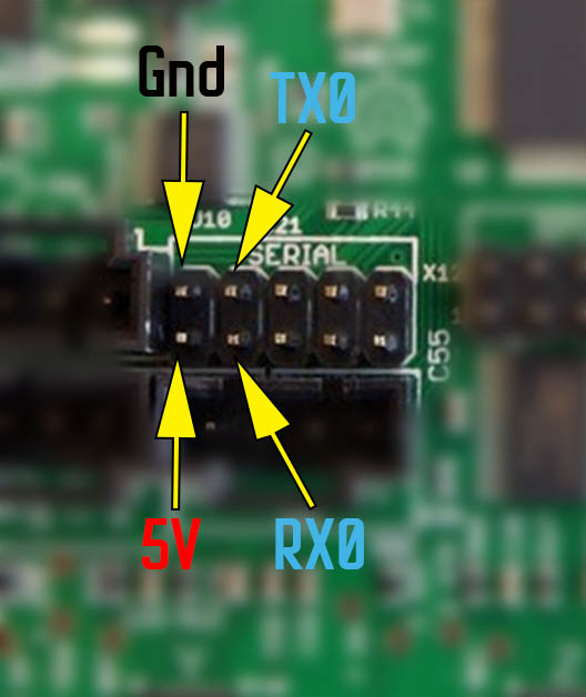
Here is the physical pinout on the Rambo board. If you run headless, then you can use RX0 and avoid the firmware upgrade. RX1 is obviously the adjacent pin. I power my Arduino Nano using the two power pins labeled in the picture.
On my pendant, I don’t use Marlin’s joystick interface. I use the Nano to read the joystick and send the commands to the MPCNC.
You can use the Nano to send the jog commands to the Rambo/Marlin. You will need to switch to relative coordinates, make the move, then switch back to absolute coordinates.
Should be fine. That comes in a 3.3V variety, so just use that instead of 5V if you have one of those. The joystick should work with either and the LEDs might be a little dimmer.
As Jeff points out, Micro Arduino boards come in 3.3V and 5.0V versions. If it is a 3.3V Micro, you will need to feed the power from the Rambo board to the Raw pin rather than the 5V pin. Also if you plan to use the Tx pin on the Rambo board to request information, you will need a voltage divider circuit or other method to protect the Rx pin on the Micro.
i am connecting my pi via the serial header you are referencing here (and a bidirectional logic level converter) and was hoping to avoid a firmware update. you mention here this is possible if running “headless,” can you clarify what headless means in this context? when i hear headless, i hear “without a display” - but that doesn’t seem right here…
Headless here means without a computer attached. The communication over the USB connection between the control board and the computer uses TX0 and RX0, so there is a conflict if you use these two pins for your PI communication. As long as the computer is not attached, communication over these pins will work. The actual change in firmware to increase the number of serial pin pairs is trivial, but you do have to go through with setting up an environment to compile the firmware.
good to know… im curious, can the serial pins be shared? if i wanted to hook up a nano to send gcode like you’ve done, would that need to be a separate serial connection?
I’m pretty sure that multiple devices on one set of pins will not work…at least without jumping through hoops like powering up/down devices. There are four serial pin pairs, so you could add the Nano to another pin pair.
I have to take a step back. Here is the code for the serial ports from configuration.h
/**
 * Select the serial port on the board to use for communication with the host.
 * This allows the connection of wireless adapters (for instance) to non-default port pins.
 * Serial port -1 is the USB emulated serial port, if available.
 * Note: The first serial port (-1 or 0) will always be used by the Arduino bootloader.
 *
 * :[-1, 0, 1, 2, 3, 4, 5, 6, 7]
 */
#define SERIAL_PORT 0

/**
 * Select a secondary serial port on the board to use for communication with the host.
 * :[-1, 0, 1, 2, 3, 4, 5, 6, 7]
 */
//#define SERIAL_PORT_2 -1
So there appears to be support for only one additional serial port. To enable, just set SERIAL_PORT_2 to the value for the TX/RX pair. so for example if you wanted to use the next pin pair on the board (TX1/RX1), you would:
#define SERIAL_PORT_2 1
You would need to dig deeper into Marlin to see what it would take to enable more serial ports.