I’m very new to the CNC world. I purchased the Primo kit. I’ve got my MPCNC Primo assembled and mostly square. The problem I’m having is I don’t quite understand how I am supposed to power this and I believe I have extra cables?
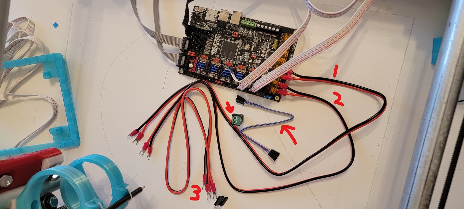
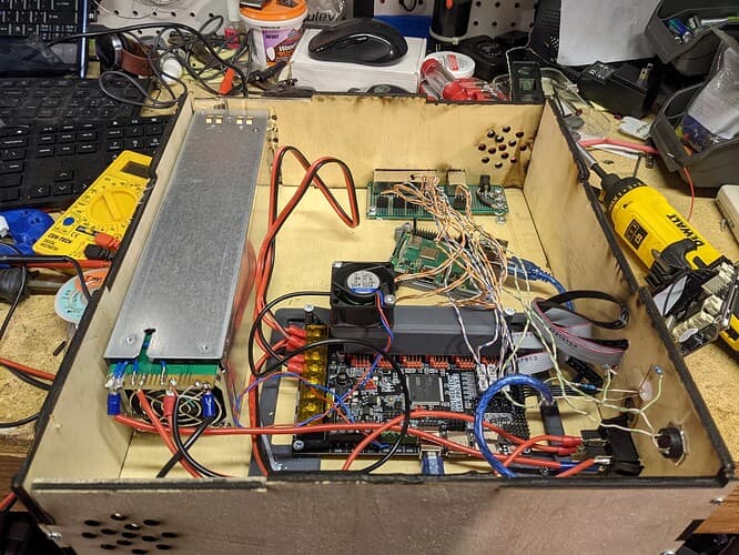
I’ve got 3 power cables as shown in the picture, and I’ve also got this 5 pin wire? I haven’t yet found a purpose for the 5 pin nor do I know what all 3 power cables are to be used for. I’m also not sure how to connect the power adapter that was supplied in the kit to any of the available power cables. If someone could walk me through this with pictures or a diagram, I would really appreciate it. Thanks all!
I am right now at the very same stage of my projekt.
Cabling is one thing, but firmware for the board and software for the PC are another.
Did you already flash the board?
How did you draw the circles?
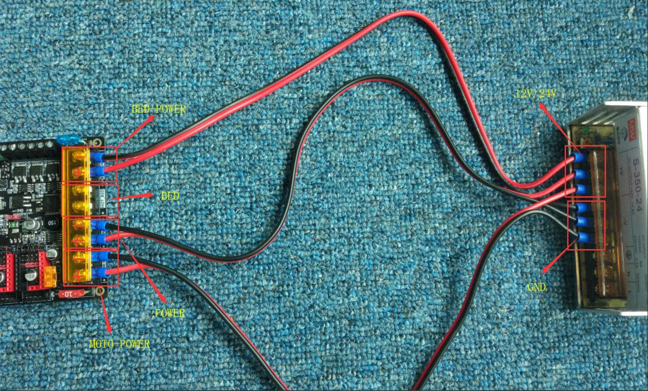
For Power wirering: Please visit the Bigtreetech Web site and look for “SKR-PRO-V1.2-user manual.pdf”
Quote: “As shown above, three sets of power lines need to be
connected to the motherboard, namely, motor power supply,
hot bed power supply and motherboard power supply, and
the extra group is hot bed interface.”
Since there is no Hot bed, just connect power and motor power to your Powersupply (12V or 24V)
Please pull your 120V / 240V plug before connecting
Are you planning to use dual endstopps?
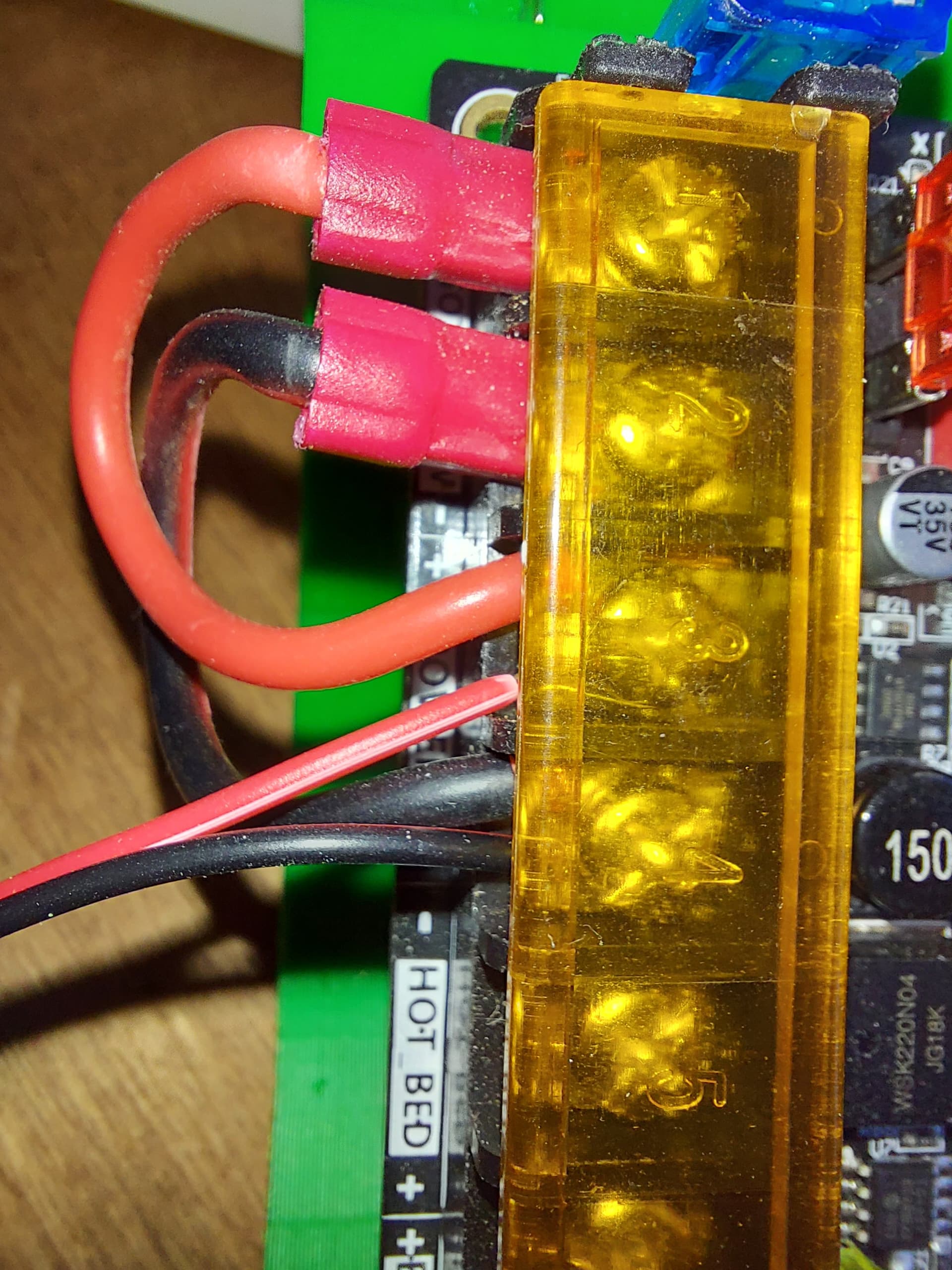
For the CNC the terminals labelled heated bed power do not need to have power to them. This is entirely for the heated bed, which we do not use, unless you want to use that for a laser or something, and even then… There are better ways.
The 2 top ones, Motor power and Power need to have power applied to them. Many people just use jumpers between them so that they both get power from the same pair or wires from the power supply.
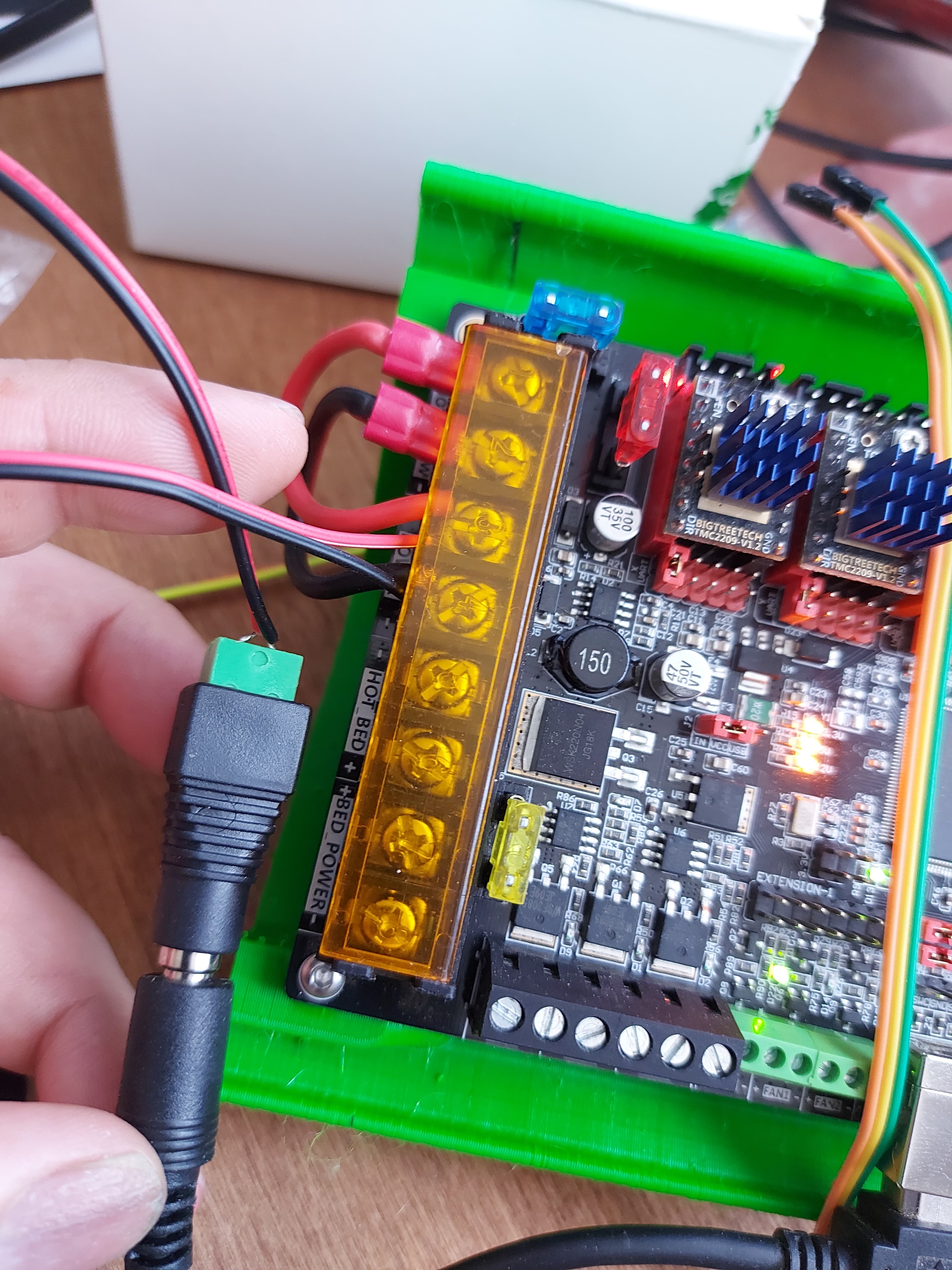
I can see in this picture that you do not have the jumpers set for UART control of the TMC drivers. I highly recommend that you read the V1 Documentation page on the SKR Pro and follow the instructions there. There are some oddities that you should observe, like bending the “diag” pin, so that you can still use end stops. (You cannot use endstops if that pin is making contact. At all.) That pin is used for sensorless homing and you would need to recompile the firmware in order to attempt to use it. This is not recommended.
I haven’t even made it to the board/software side as I haven’t yet been able to power it on. As for drawing, I attached a pencil and moved it manually to figure out build volume and verify my tolerancing.
As for the power supply, a laptop charger with that adapter I have shown is what was given. I am familiar with the kind of PSU that you attached, but not the one I was given.
I am planning to use dual endstops eventually, but I want to see if I can even get it running first before I get the dual endstops.
So, the extra power cable was simply for a heated bed or other accessory? Do you know what that 5 pin cable is about?
Could you elaborate on the jumpers for me? I followed the documentation shown and removed the jumpers for each and added a black jumper for each driver, but the sixth one as I don’t have a driver on it. Do you think that I should remove those and add one in the right place as I have done elsewhere?
This is whst I did with power wires. This one is just being tested right now so the power wires are just 24AWG wires I’d normally use for endstops, but it works for powering up. That jumper arrangement will work with the final setup, too.
The 5 pin cable could be for the LCD. That uses a 5 pin connection. You should not need that just to power it up, and for the LCD the 2 10pin connectors for “Marlin Mode” are more important, I think.
Gotcha, I think I understand now. So my plan is to pull off the JST connectors so that I’ve got bare wire. Attach the bare wire to the adapter. Plug the other end into power. Then run another power cable between power and motors. I’ll end up with an extra power cable and a 5 pin cable. Does that seem correct?
Thats the adapter rhat I am using. You can also just cut the 5.5mm plug off of the power brick and use the wires inside there. I still want to use that power brick with a laser though.
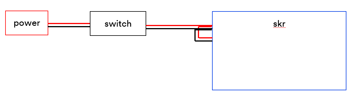
The #1 wire (you labeled in your picture) goes to the #2 wire board connections and the #2 wire goes to the power switch and #3 goes from the switch to the power supply.
Oh you’re right, I did mean spade connectors. I would prefer running the bare wire into the adapter itself as opposed to cutting off the adapter and just using the wires if that’s feasible anyway.
If I understand this right. You are running wire #1 from the board to a power switch, than running wire #2 from the power switch to the board power, than running wire #3 from board power to motor power on the board. is that right? As I do not have a power switch, I should have a spare wire, correct?