I’m new here and haven’t cut anything except some test pieces with my MPCNC, but I’m coming up on a project that could really benefit from it - the Pinewood Derby.
My 9 year old son and I are entering separate cars in the derby this year and we’ve developed some pretty intricate designs thinking we would have the benefit of the MPCNC to cut them out. If I was cutting them from a sheet of plywood, that would be pretty straight forward, but we are required to use the pine block included in the kit there are portions of the 7 x 1.75 x 1.25 inch block’s perimeter that are untouched in the final design, so my zero point needs to be dead on.
My plan right now is to mill out a 7 x 1.75 inch pocket in a 2x4 and attach the pinewood derby block to that with some double-sided tape. That at least gets me the 2d shape. I haven’t tried doing any 2.5d work with my MPCNC yet, so please share any tips.
Right now the cars are designed in SolidWorks. I can resave them as STLs, DXFs, or probably just about any other file type.
I’ve done that, where I mill out a pocket in absolute space where I put a piece that I’m cutting with the CNC. It works quite well, and then you have a machine made reference.
Another way it to put locating pins into the spoilboard, but probably not as useful for this sort of thing.
There are many approaches to solve this problem. There are really two pieces to the problem. First you need to have the router precisely at a coordinate relative to the block, and your stock must be parallel to the axes of your MPCNC. From your starting point, I think the easiest path would be to make a quick fixture.
Attach a thinnish piece of scrap wood to your spoil board.
Model a pocket the size of your Pinewood Derby blank in your CAD program of choice. You will need to model in dog bone fillets in the corners. Since the fixture is scrap, just putting circles at the corners bigger than the bit size will do the job.
Navigate to the center of the scrap wood with the bit touching the top and execute a G92 X0 Y0 Z0 to reset the origin. Note some setups automatically add this line of g-code, and if you are using the Marlin menu on a display on your control board, there is a V1 menu item to reset the origin.
Have the MPCNC cave out the pocket you modeled in the scrap wood. Leave the steppers engaged at the end of the operation.
Move the router up and, using double sided tape, put the Pinewood Derby blank in the pocket.
Set router bit to the top of the blank and execute a G92 Z0
Start your Pinewood Derby carving.
Some random thoughts:
If you built MPCNC with electronic end stops, or have calibrated hard stops, you can first home your machine, and then navigate electronically to the center of your scrap board you will use for your fixture. Record the X, Y offset before you execute your G92. That way you can return to the center of your fixture even if you power off the electronics.
While I’ve written about the “center,” the same thing can be done if you want to use some other corner of your stock or some position other than the top of the stock. You just need to make the CAM for your pocket and the CAM for your derby car carving use the same staring point.
I don’t know anything about SolidWorks, and you don’t say how you are going to do the CAM. I don’t know if there is a postprocessor for SolidWorks that outputs Marlin g-code. Both EstlCAM and Fusion 360 (including the free version) can use STL files for relief carving. If you go with Fusion 360, we can point you to a good postprocessor.
I’d buy a piece 1.5" foam board and practice your car carving on the foam before moving to the wood. In addition to being cheaper, you can use much higher feedrates when carving foam and perfecting your toolpaths.
Edit: in rereading my post, my steps assume that your toolpath to pocket the scrap wood returns to the origin (at least X and Y) after carving. This is a setting that needs to be turned on in some CAM solutions, but you can send a G1 X0 Y0 Z0 from Repetier-Host to do it manually.
Wow! Thanks for the help.
I left out some details.
What I’ve been doing on my practice pieces so far is taking the STL from solid works, bringing it into Estlcam to generate the Gcode, and then interacting with the MPCNC controller with Repetier-host. I haven’t tried putting anything on a SD card yet. I’m connected to the MPCNC from the PC via USB cable.
I modeled a 1.75" x 7" block in SolidWords, saved it as a DXF (2D) and imported it to Estlcam. Estlcam converted it to G-code an I selected 0.300" depth using a 3/32 " endmill with 0.040" Z-steps. I put loaded that in Repetier-Host.
I clamped a scrap 2x4 to the table and brought the router bit within 1mm of the top of the 2x4 near one corner of the 2x4.
I think Repetier-Host only shows mm. I don’t think there’s an option for inches. With the exception of the sharp, pointy things, I probably just need to work in metric exclusively. It went row by row milling the pocket and then went around the perimeter before stepping down ~1mm. It did this 8 times, leaving thin “rows” between the rows that it cut. I guess the stepover is too much. I did not do a low stepover finishing pass because this was all experimental and didn’t see a need to take that much time.
When it reached the end of doing that, the z-axis retracted and then went around the perimeter 8 more time, cutting away about 1mm on each edge and dropping down 1mm on each trip around. This made the pocket too big. I’m not sure why that happened. I can only figure I did something wrong in Estlcam.
I have not yet set up dust collection for my MPCNC, so I stood there with the shop vac hose the entire time. I need to do that sooner rather than later.
Although this was not a complete success, I am encouraged by the outcome and I continue to get this wonderful tool fine-tuned for my needs.
I’m not completely clear on what you did, and I’m not and EstlCAM user. I’m assuming you are trying to cut the pocket. What you want to do is model the pocket, not the block. Your model should look like a thin square of wood with a square hole in the middle. And you don’t need much of a pocket, nor much thickness in the wood. If you have it, a piece of 1/8" hardboard, or 1/8" plywood would work great, and you only need a 1mm or 2mm pocket. You do need to dogbone the corners. If you set the origin of your cut to the middle of the stock, then the size of the scrap wood can be anything bigger than your model or DXF outline. I suggesting something like either of these two (though the DXF on the right is the better choice):
And in EstlCAM, you want to pocket out the rectangle to some depth. Your cutting was likely too large because you cut on the outside instead of the inside.
Set the car up so 85% of weight on rear axles. Car will still be accelerating when others are starting to slow. Polish the axles/ nail heads. Lube with powdred graphite. Ever so slight sanding of wheels to remove casting seam. Ever so light crown on wheel so most weight on crown of wheel. Drill one of front wheel axles a 32nd higher, so technically running on three wheels, reducing friction. Spend time aligning the wheels to run as straight as possible, as rubbing on side of track slows you down. Technically, not cheating, but skirts the Grey area of the boy scout rules… no where does it say all four wheels have to touch the track…
Our pack rules actually address the wheel alignment. All 4 wheels must be installed on the car, but they specifically say all 4 do not have to touch the track. It also states that we cannot notch/shape the axles, but we can remove the burrs. Same thing for the wheels - no reshaping allowed, only removing the casting marks. The axles must use the slots provided in the block, but we can bend the axles to prevent the wheel from rubbing against the car body and hold one wheel up.
Not everyone has the capability to build a really great car, so I appreciate that it makes it accessible for everyone. Next week’s pack meeting is actually a speedshop. Several parents will bring tools (bandsaws, small drill presses, etc) to help kids make their cars if they don’t have the resources to make them at home.
You can spend a lot of money buying special tools and prepared pieces (car bodies, lathe-turned wheels and axles). If the pack was big enough, maybe we’d have different classes where some of those things would be allowed, but we’re not. The only exception to the rule is that they do have an outlaws class where your car can weigh up to 15 oz.
Neither mine, nor my son’s car will be in that class. My car will be in the siblings/parents class where he will race with the Cub Scouts, but either of our cars would be legal (and hopefully competitive) in either group. This is only the second year he and I have done this. I helped him build his own car 2 years ago, but I did not enter one of my own. There was no PWD last year for our pack.
As it is, we bought the tungsten weights and the wheel mandrel to be able to chuck the wheels into a drill press and smooth out the molding marks.
When I was a kid, I was handed the kit with a block for a car and handed a rasp. I got it sort of car shaped and then we painted it and glued the axles on. I still had a lot of fun, but didn’t come close to winning.
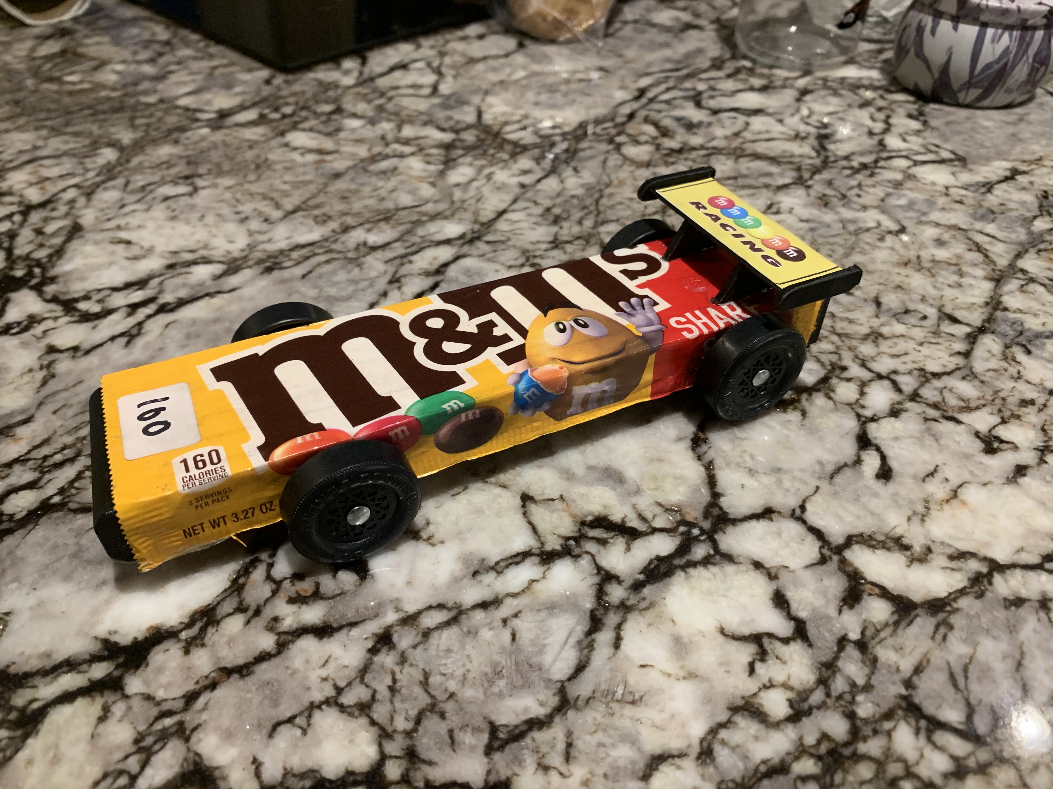
My 6 year old told me that he wanted a car that was easy to build and didn’t use dads fancy tools that he’s not allowed to use.Dad was very disappointed… so we cut the block in half and wrapped it in a candy wrapper which he was happy about.
At least we got to use the 3D printer and cricut since he’s now allowed to use those.
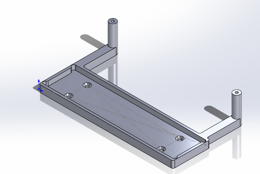
I’ve been making some trial runs with the MPCNC with mixed results. I 3D printed a holding fixture with a zero-point on it that marks the exact height of the top of the block when it is in the fixture. The fixture if screwed down to a 1x4. There is a second “zero-point” tower 170mm away so I can make sure I have it aligned parallel to the x-axis of the MPCNC.
I think I’m solid on that part.
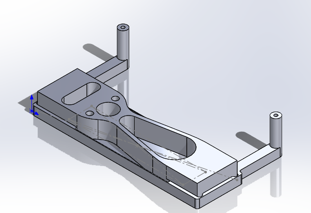
My plan was to make an assembly with the model of the car in SolidWorks, save it as an STL, and then bring that into Estlcam. When I did that, it Estlcam opens the two pieces in the assembly separately. So now I have added onto the model of the holding fixture shown above to add the outline of the car as one piece and brought that into Estlcam.
When I do that, I get only the outline. I ended up bringing in that model as a DXF and losing the 2.5d abilities. I have a little more shaping to do with the bandsaw and beltsander, but Ineed to get going with the PWD car builds instead of perfect the CNC technique.